Abstract
Explicit solutions to vertical and horizontal displacements are derived for large deformation of a cantilever beam under point load at the free end by an improved homotopy analysis method (IHAM). Quadratic and cubic nonlinear differential equations are adopted to construct more proficient nonlinear equations for vertical and horizontal displacements respectively combined with their currently available nonlinear displacement equations. Higher-order nonlinear iterative homotopy equations are established to solve the vertical and horizontal displacements by combining simultaneous equations of the constructed nonlinear equations and the auxiliary linear equations. The convergence range of vertical displacement is extended by the homotopy-Páde approximation. The explicit solutions to the vertical and horizontal displacements are in favorable agreements with the respective exact solutions. The convergence ranges for a relative error of 1% by the improved homotopy analysis method for vertical and horizontal displacements increases by 60% and 7%, respectively. These explicit formulas are helpful in practical engineering design for very slender structures, such as high-rise buildings and long bridges.
1. Introduction
In view of the shortage of land worldwide, especially in metropolitan areas, high-rise building is a prioritized land-efficient architectural form developed more than 100 years ago. High-rise building is the product of the comprehensive application of modern sciences and engineering technologies. Smooth construction and sustainability of this new structural form depends on more accurate calculation theory and method than those for non-high-rise structures in light of that the extrusion of high-rise building into space could be as high as 800 m plus, and slight artefacts could be exaggerated into intractable unpredictability. Since the 21st century, beam-like structures have achieved overwhelming popularity, such as in high-rise buildings [1,2], long-span bridges [3,4], robots and aerospace; however, analysis methods for this form of structure are still those conventional Euler-Bernoulli laws for large deflection beams, which contain implicit integral to hinder general engineering application. An explicit higher-resolution analysis method is expected to tackle the high nonlinearity in high-rise buildings or long bridges.
The general theory of elastic deflection is called Elastica. To solve a general problem of elastic large deflection, the equivalent load, deflection and longitudinal displacement can be expressed by an analytic expression of elliptic integrals with free-end rotation angle as parameters [5]; indeed, the results have been reported extensively in the classical works of elastic mechanics [6,7,8]. For a cantilever beam subject to point load, the solution to this elastic problem is still an implicit solution with an elliptic integral.
In this study, the high-rise building is simplified as a large deformation of a cantilever beam subject to point load at the free end, for example, of a loading extremity, as shown in Figure 1. Given that the traditional analytical methods for solving nonlinear equations such as perturbation [9], methods introduced in [10,11], Adomian decomposition method [12], and -expansion method [13], in addition to the elliptical integrals mentioned above, cannot provide accurate, convergent and simple solutions, we aim to derive an explicit and accurate expression for rotation angle , vertical displacement and horizontal displacement to minimize the potential unpredictability in the large deformation of the long cantilever-like building.
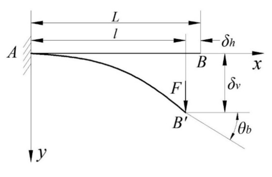
Figure 1.
Large deformation of beam under point load at the free end.
Unlike the perturbation technique, the homotopy analysis method (HAM) is independent of any small/large physical parameters. HAM provides us great freedom to choose equation-type and solution expression of the high order approximation equations. A convergence-control parameter is introduced into the series solutions to guarantee the convergence. HAM distinguishes itself from other analytic approaches to be applied to complicated problems with strong nonlinearity [14,15,16,17,18,19,20,21,22,23,24,25,26,27]. The Föppl–Von Kármán’s plate equations were solved by HAM [28,29]. Especially, the steady-state resonant waves were firstly predicted by the HAM in theory [21,22,30,31], which were then confirmed experimentally [30].
Ji Wang et al. derived an explicit solution to the large deformation of a cantilever beam under point load at the free end with HAM [32]. However, the improficiency of this method is identified to be a low convergence rate due to the step-by-step iteration of solutions of linear differential equations to approximate the exact solutions of complex non-linear differential equations; moreover, it fails to serve explicit solutions of vertical and horizontal displacements for large deformation of the beam.
In our previous paper, “Explicit Solution to Large Deformation Cantilever Beam by Improved Homotopy Analysis Method I: ROTATION ANGLE”, an improved homotopy analysis method (IHAM) was proposed. In IHAM, an auxiliary nonlinear operator is introduced to improve the convergence rate and extend the convergence range. The improved homotopy analysis method was used to obtain the explicit solution to the rotation angle for the large deformation of a cantilever beam under point load at the free end.
For small deflection, the horizontal displacement of the cantilever beam is neglected and only the deflection and rotation angle are calculated. For large deflection, horizontal displacement is signified not to be neglected. Based on the explicit solution to the rotation angle obtained in our previous paper, explicit expressions for the deflection and horizontal displacement are derived using the improved homotopy analysis method in this paper.
2. Improved Homotopy Analysis Method
2.1. Problem Description
The bending equations of a uniform cross-section beam with large deformation are [5,6,7,8]
subject to boundary conditions
where is the arc-coordinate of the neutral axis of the beam; denotes the horizontal coordinate from the fixed end; represents the length of the beam; stands for the point load at the free end; is the bending stiffness of the beam; specifies the rotation angle of cross-section of the beam; and is the horizontal distance of two ends and is unknown.
Differentiating the equation with respect to and then using the dimensionless variables , , , , , and , the original equations become
subject to boundary conditions
where the prime denotes the differentiation with respect to .
For infinitesimal deformation, the below linear equations are sufficiently accurate
subject to boundary conditions
Accordingly, the solutions are
The rotation angle, vertical and horizontal displacement of cross-section plane at end as denoted by , , , are calculated to be
In our previous paper, “Explicit Solution to Large Deformation Cantilever Beam by Improved Homotopy Analysis Method I: ROTATION ANGLE”, the improved homotopy analysis method was proposed to solve Equations (2.3a) and (2.4a), and a series of solutions to the rotation angle are derived as [27]:
where
In this paper, we apply the improved homotopy analysis method to derive the explicit expressions of deflection and horizontal displacement using Equations (2.3b), (2.4b), (2.3c), and (2.4c) on the basis of the derived explicit expressions of rotation angle in Equations (2.9) and (2.10).
2.2. Fundamentals of Improved Homotopy Analysis Method
For quick reference, the new improved homotopy analysis method (IHAM) is briefed. The IHAM is essentially different from the HAM. Table 1 compares the formulations of IHAM and HAM.

Table 1.
Comparison of improved homotopy analysis method against homotopy analysis method.
Substantial difference lies in the different construction methods. HAM constructs a higher order nonlinear iterative homotopy differential equation by the selected linear differential equation and the original non-linear differential equation. However, IHAM builds up a higher-order nonlinear iterative homotopy differential equation using the selected linear differential equation, the selected simple non-linear differential equation and the original non-linear differential equation (See Table 1).
Generalized Equation (2.3b) or Equation (2.3c) have the form of
where in is a derivable function in compliance with the boundary conditions of , , , ; is the selected polynomial function of an independent variable in Equations (2.9) and (2.10). The boundary condition in Equation (2.4b) or Equation (2.4c) can be expressed as
Note that it is unnecessary to assume the existence of any small or large parameters in Equation (2.11). Thus, the proposed approach is general.
Linearizing original Equation (2.11) yields
which complies to the boundary condition of
We choose the simplest auxiliary nonlinear equations of
herein, , , and are undetermined coefficients; and , , . which satisfies the boundary condition of
Detailed formulation for the improved homotopy analysis method could be found in our previous paper titled “Explicit Solution to Large Deformation Cantilever Beam by Improved Homotopy Analysis Method I: ROTATION ANGLE”.
3. Vertical Displacement of Cantilever Beam by IHAM
3.1. Zero Order Deformation Equation
The nonlinear boundary value Equations (2.3b) and (2.4b) are then solved by IHAM to derive explicit form for . To start with, is expressed by power series of , i.e.,
where is a constant coefficient. Since Equation (2.7b) from linear equation is an appropriate initial guess, we choose
The equivalent nonlinear Equation (2.3b) becomes
subject to boundary condition
where is the coefficient, and .
When , Equation (3.3) becomes linear Equation (2.5b), so that
When , Equation (3.3) becomes
Equation (3.6) is an approximate expression of the second-order Taylor expansion of sine function in view of that
According to the original Equation (2.3b) and the equivalent Equation (3.3), we define a nonlinear operator as
where is an embedding parameter; , are dependent on and ; is a control parameter to represent the convergent region, and .
When , there is
If , it yields
Letting
be an auxiliary linear operator, and denotes a nonzero auxiliary parameter (called convergence-control parameter), a homotopy is then constructed as
When , we have
If , there is
Thus, by enforcing
we have a family of equations
subject to the boundary condition of
When , we have
When , Equations (3.15) and (3.16) are equivalent to the original Equations (2.3b) and (2.4b), provided that
Thus, as increases from 0 to 1, evolves smoothly from the specified initial guess to the solution of Equations (2.3b) and (2.4b).
With reference to Equation (3.17), by expanding into Taylor series of the embedding parameter , we have
where
It is worth noting that the zero order deformation Equation (3.15) contains auxiliary parameters , . Auxiliary function has the form of
Assuming that and are properly chosen, so that Equation (3.18) is convergent at . Thus, we have
The governing equations of can be deduced from the 0th-order deformation Equations (3.15) and (3.16).
3.2. High Order Deformation Equations
Substituting Equation (3.19) into Equation (3.15) and differentiating Equation (3.15) times with respect to the embedding parameter , then dividing by and setting , we have the th-order deformation equation as below,
Equation (3.21) is subject to boundary conditions of
where
and
Combining Equations (3.8) and (3.23), we have
These equations can be solved by symbolic calculation software such as Maple, Matlab, etc. Thereafter, the linear high-order deformation Equations (3.21) and (3.22) can be solved explicitly.
The solutions given by the IHAM contains auxiliary parameters and , which control and adjust the convergence region and rate of IHAM solution series.
3.3. Vertical Displacement at Free end of Cantilever Beam
3.3.1. Accurate Solution of Vertical Displacement
From Equation (2.3), the transcendental equation used to solve is as follows
where
herein is complete elliptic integral of the second kind; is the elliptic integral of the second kind; and
From Equation (2.8b), the linear solution of the vertical displacement at the free end is
When the relative error , the convergent region of the linear solution is
3.3.2. Control Parameter for Convergent Region
Combining Equation (2.3b) with Equation (3.3) gives
When , we have
Accordingly, the optimal convergence parameter for the full coverage is derived as
When , , , the 2nd-order approximation of by IHAM is
For example, the 2nd-order approximation of with , is
When the relative error , the convergent region of the 2nd-order approximation by IHAM is
Table 2 shows 2nd order numerical solutions by IHAM with different values compared with exact solutions . The relative error in Table 2 is calculated by

Table 2.
2st-order numerical solutions by IHAM () with different values compared with exact solutions .
After two iterations, when , the convergence region of is . When , the convergence region of is , whence the convergence region is expanded by compared to the case with .
When , increases from 0 to 1, the series of solutions of vertical displacement converge to the exact solution with relative error to the exact solution is less than 1%, so that the effective region of is identified to be .
Thus, the optimal control parameters for the convergence region of the improved homotopy analysis method is identified to be .
3.3.3. Control Parameters for Convergence Rate
By IHAM, when , , , , the 10th-order approximation of is
When the relative error , the convergent regions of the 10th-order approximation by IHAM are
Table 3 compares the 10th-order numerical solutions with the exact solutions. The relative error in Table 3 is calculated by

Table 3.
10th-order numerical solutions by IHAM with different values of () compared with exact solutions .
After iterative calculations, when , the convergence region of is . When , the convergence region of is . When , the convergence region of is . It is seen that when , the convergence region is larger than that with , while it is larger than that with (See Table 3).
Accordingly, the optimal control parameters of convergence rate for the 10th-order approximation solution to the vertical displacement is identified to be .
3.3.4. 30th-Order Approximation Solution of Vertical Displacement
When , , the 30th-order approximation of by IHAM is
When the relative error , the convergent region of the 30th-order approximation by IHAM is
When , , the 30th-order approximation of by HAM is
Table 4 compares the above numerical solution with the exact solution. The relative error in Table 4 is calculated by

Table 4.
30th-order numerical solutions by IHAM (, , ) compared with exact solutions .
When the relative error , the convergent regions of the 30th-order approximation by HAM () are
When , , the 30th-order approximation of by IHAM is
When the relative error , the convergent regions of the 30th-order approximation by IHAM () are
From Table 4, the improved homotopy analysis method extends the convergence region from by the homotopy analysis method [32] to , which is an increase.
From the above comparison, it can be seen that the expansion rate of the convergence region for vertical displacement by IHAM against that by HAM increases with the increasing iterations.
3.3.5. Homotopy-Páde Approximation
By application of the homotopy-Páde acceleration technique [27], the convergence region can be greatly enlarged. For example, when , , , the homotopy-Páde approximation of in Equation (3.44) by HAM can be written as
When the relative error , the convergent regions of the homotopy-Páde approximation by HAM are
When , , , the homotopy-Páde approximation of in Equation (3.47) by IHAM are
When the relative error , the convergent regions of the homotopy-Páde approximation by IHAM are
Table 5 shows that numerical solutions of homotopy-Páde approximation by IHAM compares with exact solutions . The relative error in Table 5 is calculated by

Table 5.
Numerical solutions of homotopy-Páde approximation by IHAM. (, , , ) compared with exact solutions .
From Equations (3.50) and (3.52), the improved homotopy analysis method extends the convergence region from to for the homotopy-Páde approximate solution compared with the homotopy analysis method [32], which is a increase.
Figure 2 compares the 30th-order iteration solution and the exact solution of the vertical displacement. From Figure 2, it can be observed that
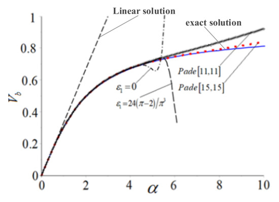
Figure 2.
Comparison of vertical displacement at the free end with .
- the difference between the linear solution and the exact solution is remarkable;
- the 30th-order improved homotopy analysis solution for is much closer to the exact solution than does the 30th-order homotopy analysis solution for ;
- the convergence range and rate have been greatly improved by the expression by homotopy-Páde approximation;
- the Páde approximation solution by IHAM is more approximating to the exact solution than does the Páde approximation solution by HAM.
4. Horizontal Displacement of Cantilever Beam by IHAM
4.1. Zero Order Deformation Equation
The nonlinear boundary value Equations (2.3c) and (2.4c) are then solved by IHAM to give explicit expression for . To start with, is expressed by the power series of , so that
where is a constant coefficient. Linear Equation (2.7c) is specified as initial guess. Accordingly, we choose
The equivalent nonlinear equation of Equation (2.3c) is
subject to boundary condition of
where is the correction coefficient of the convergent region, and .
When , Equation (4.3) becomes the linear Equation (2.5c), so that
When , Equation (4.3) becomes
Approximation expression of the second-order Taylor expansion of cosine function can be written as
According to the original Equation (2.3c) and the equivalent Equation (4.3), we define a nonlinear operator as
where is an embedding parameter; , are the functions dependent on and ; is a control parameter for the convergent region, and .
When , there is
If , it yields
Specifying
as an auxiliary linear operator, and denoting as a nonzero auxiliary parameter (convergence-control parameter), a homotopy is constructed as
Accordingly, when , we have
If , it becomes
Thus, by enforcing
we have a family of equations
subject to boundary conditions
When , we have
When , Equations (4.16) and (4.17) are equivalent to the original Equations (2.3c) and (2.4c), provided that
Thus, as increases from 0 to 1, evolves from the known initial guess solution to the exact solution of Equations (2.3c) and (2.4c).
With reference to Equation (4.10), by expanding into Taylor series of the embedding parameter , we have
where
It is worth noting that the zero order deformation Equation (4.16) contains auxiliary parameters , . And the auxiliary function has the form of
Assuming that and are properly chosen, so that Equation (4.19) is convergent at , thus, we have
The governing equations can be deduced from 0th-order deformation Equations (4.16) and (4.17).
4.2. High Order Deformation Equations
Substituting Equation (4.20) into Equation (4.16) and differentiating (4.16) times with respect to the embedding parameter , then dividing by and setting , we have the th-order deformation equation as below
Equation (4.24) is subject to boundary condition of
where
and
Combining Equations (4.8) and (4.26), we have
The right-hand side term of the above equations can be derived by symbolic calculation software such as Maple, Matlab, etc. Thereafter, explicit form of solution to the linear high-order deformation Equations (4.24) and (4.25) have been derived.
4.3. Horizontal Displacement at Free End of Cantilever Beam
4.3.1. Accurate Solution to Horizontal Displacement
Accordingly, in Equation (2.3c), the transcendental equation to solve is as follows
With reference to Equation (2.8c), the linear solution of the horizontal displacement at the free end is
4.3.2. Explicit Solution to Horizontal Displacement by IHAM
The solutions by IHAM contains two auxiliary parameters and , which control and adjust the convergence region and rate of IHAM solution series.
For example, the 10th-order approximation of with , , , , is derived as
When the relative error , the convergent regions of the 10th-order approximation by IHAM are
The 20th-order approximation of with , , , , is expressed as
When the relative error , the convergent region of the 20th-order approximation by IHAM is
The 30th-order approximation of with , , , , is
When the relative error , the convergent regions of the 30th-order approximation by IHAM are
Table 6 compares the above numerical solutions with the exact solutions. The relative error in Table 6 is calculated by

Table 6.
30th-order numerical solutions by IHAM (, , ) compared with exact solutions .
From Table 6, IHAM extends the convergence regions from by HAM to , which is increase.
Figure 3 shows the relationship between horizontal displacement and concentrated force at the free end. From Figure 3, it is observed that
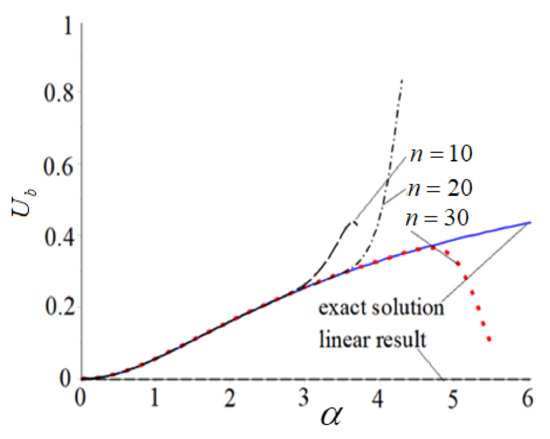
Figure 3.
Horizontal displacement at free end.
- the difference between the linear solution and the exact solution is remarkable;
- from result of Equation (4.32), result of Equation (4.34) and n = 30 result of Equation (4.37), the convergence regions of horizontal displacement increases with increasing iterations.
5. Discussions and Conclusions
5.1. Error Analysis of Vertical Displacement
The influence of the control parameters and on the error of vertical displacement after iterations with is then discussed.
After five iterations, the improved homotopy analysis method is adopted to solve the Equations (3.21) and (3.22) to yield the solution to the original Equations (2.3b) and (2.4b) as below
When , Equation (5.1) becomes
When , the exact solution is . When the iteration is five times, the relative error between the result by IHAM and the exact solution can be expressed as
When , Equation (5.2) becomes
According to Equations (5.3) and (5.4), the relative error curve of control parameter is a broken line. When the relative error is less than , the convergence interval is , which is the effective region of .
Figure 4 shows the relative errors curve of Equation (2.3b) when , . From Figure 4, when , the relative error is the minimum.
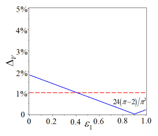
Figure 4.
Relative errors curve of Equation (2.3b) when , .
When , Equation (5.2) becomes
According to Equations (5.3) and (5.5), the relative error curve of control parameter is a quintic power function. When the relative error is less than , the convergence interval is , which is the effective region of .
Figure 5 gives the relative errors curve of Equation (2.3b) when , . From Figure 5, when , the relative error is the minimum.
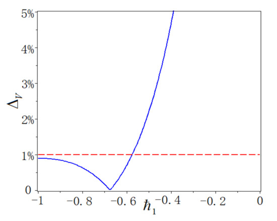
Figure 5.
Relative errors curve of Equation (2.3b) when , .
5.2. Error Analysis of Horizontal Displacement
The influence of the control parameter and on the error of horizontal displacement after 5 iterations when is then discussed.
After five iterations, the improved homotopy analysis method is adopted to solve the Equations (4.24) and (4.25) to derive the solution to the original Equations (2.3c) and (2.4c). Thus,
When , Equation (5.6) becomes
When , the exact solution is . After 5 time iterations, the relative error between the results by IHAM method and the exact solution can be written as
When , Equation (5.7) becomes
According to Equations (5.8) and (5.9), the relative error curve of control parameter is a broken line. When the relative error is less than , the convergence region is , which is the effective region of .
Figure 6 shows the relative errors curve of Equation (2.3c) when , . From Figure 6, when , the relative error is the minimum.
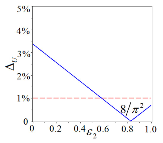
Figure 6.
Relative errors curve of Equation (2.3c) when .
When , Equation (5.7) becomes
According to Equations (5.8) and (5.10), the relative error curve of control parameter is a quintic polynomial curve. When the relative error is less than , the convergence interval is , which is the effective region of .
Figure 7 depicts the relative errors curve of Equation (2.3c) when , . From Figure 7, when or , the relative error is the minimum.
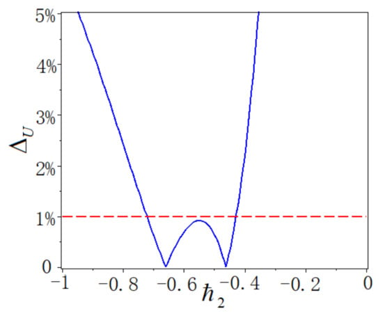
Figure 7.
Relative errors curve of Equation (2.3c) when , .
5.3. Conclusions
In this paper, an improved homotopy analysis method (IHAM) is applied to derive complete expressions of vertical and horizontal displacements of a cantilever beam under point load at the free end. In fact, the proposed method is a semi-analytical method since many numerical algorithms are used.
The linear solution is only valid for small . For large , the nonlinear effect of the equation cannot be neglected. A family of the explicit solutions of the rotation angle, the vertical and horizontal displacements of a cantilever beam under a point load at the free end are obtained by IHAM, which are summarized in Table A1 for 30th-order approximation. The current explicit solutions with different parameters and solution schemes match well with the exact solutions from elliptical integrals; however, our solutions for the current problem by the proposed IHAM, especially Equations (3.36) and (4.31), are explicit and simple compared with the exact solution from the elliptical integrals which requires solving a transcendental equation. The current solution is easy to calculate with the explicit polynomial expressions, which should be, thus, prioritized for practical engineering applications with minimal requirements on the calculation and computation.
By solving the exact bending equation of a cantilever beam, we demonstrate the superior proficiency of IHAM over a class of existing equations in solid mechanics. The improved homotopy analysis method has great superiority compared over the traditional homotopy analysis method in view of the very much increased rate and precision of convergence as well as the substantially enlarged convergence range.
The convergence ranges of the rotation angle and vertical displacement are extended by the homotopy-Páde approximation, whereas it does not avail horizontal displacement.
In summary, the 30th-order improved homotopy analysis solutions and exact solutions of the angular, vertical and horizontal displacements of large deflection cantilever beams by Equations (3.42), (3.47) and (4.35) are compared in the following Appendix A table. It can be concluded from this study that the proposed IHAM can be applied to solve a general strong nonlinear problem in structural analysis.
Author Contributions
Conceptualization and methodogoly, Y.L. and X.L.; validation and data curation, C.X. and S.H.; formal analysis, Y.L.; investigation, X.L.; writing—original draft preparation, C.X.; writing—review and editing, X.L.; visualization, S.H.; supervision, Y.L.; project administration, Y.L.; funding acquisition, X.L. All authors have read and agreed to the published version of the manuscript.
Funding
This research was supported by the National Natural Science Foundation of China (Grant No. 11972145) and Tianjin Excellent Science and Technology Commissioner Support Project (Grant No. 20YDTPJC0080).
Institutional Review Board Statement
No application.
Informed Consent Statement
No application.
Data Availability Statement
No application.
Acknowledgments
This work was funded by the National Natural Science Foundation of China (Grant No. 11972145) and Tianjin Excellent Science and Technology Commissioner Support Project (Grant No. 20YDTPJC0080).
Conflicts of Interest
The authors declare no conflict of interest.
Appendix A

Table A1.
30th-order numerical solutions , , by IHAM compared with exact solutions , and .
Table A1.
30th-order numerical solutions , , by IHAM compared with exact solutions , and .
| Rotation Angle |
Vertical Displacement |
Horizontal Displacement | ||||
|---|---|---|---|---|---|---|
| Exact Solutions | Exact Solutions | Exact Solutions | ||||
| 0 | 0 | 0 | 0 | 0 | 0 | |
| 0.3 | 0.094719 | 0.094751 | 0.098991 | 0.099038 | 0.0058994 | 0.0059052 |
| 0.6 | 0.18509 | 0.18530 | 0.19235 | 0.19266 | 0.022488 | 0.022563 |
| 0.9 | 0.26801 | 0.26853 | 0.27621 | 0.27699 | 0.047034 | 0.047300 |
| 1.2 | 0.34206 | 0.34291 | 0.34901 | 0.35030 | 0.076400 | 0.076933 |
| 1.5 | 0.40714 | 0.40825 | 0.41098 | 0.41271 | 0.10794 | 0.10872 |
| 1.8 | 0.46394 | 0.46520 | 0.46326 | 0.46534 | 0.13981 | 0.14076 |
| 2.1 | 0.51342 | 0.51477 | 0.50732 | 0.50966 | 0.17085 | 0.17190 |
| 2.4 | 0.55661 | 0.55798 | 0.54455 | 0.54709 | 0.20046 | 0.20153 |
| 2.7 | 0.59444 | 0.59580 | 0.57618 | 0.57888 | 0.22835 | 0.22939 |
| 3.0 | 0.62772 | 0.62905 | 0.60325 | 0.60605 | 0.25442 | 0.25540 |
| 3.3 | 0.65714 | 0.65843 | 0.62658 | 0.62945 | 0.27870 | 0.27961 |
| 3.6 | 0.68327 | 0.68452 | 0.64684 | 0.64975 | 0.30128 | 0.30210 |
| 3.9 | 0.70659 | 0.70774 | 0.66455 | 0.66746 | 0.32228 | 0.32310 |
| 4.2 | 0.72749 | 0.72821 | 0.68014 | 0.68282 | 0.34180 | 0.34302 |
| 4.5 | 0.74630 | 0.74664 | 0.69397 | 0.69571 | 0.35999 | 0.36042 |
| 4.8 | 0.76329 | — | 0.70629 | 0.70724 | 0.37695 | — |
| 5.1 | 0.77870 | — | 0.71735 | 0.72349 | 0.39279 | — |
| 5.4 | 0.79272 | — | 0.72731 | — | 0.40762 | — |
| 5.7 | 0.80552 | — | 0.73635 | — | 0.42153 | — |
| 6.0 | 0.81723 | — | 0.74457 | — | 0.43459 | — |
| 1 | 1 | 1 | 1 | 1 | 1 | |
References
- He, G.K. High-rise building structure facing the 21st century. Build. Sci. 2002, 11, 1–4. (In Chinese) [Google Scholar]
- Hu, S.D.; Fang, E.H. Analysis of the world’s tallest 100 buildings. Constr. Technol. 2004, 35, 540–542. (In Chinese) [Google Scholar]
- Xiang, H.F. Prospect of world bridge engineering in the 21st century. J. Civ. Eng. 2000, 33, 1–6. (In Chinese) [Google Scholar]
- Qin, R. Long-Span Bridge Structure; Science Publishing House: Beijing, China, 2008. [Google Scholar]
- Gere, J.M.; Timoshenko, S.P. Mechanics of Materials; PWS Publishing Company: Boston, MA, USA, 1997. [Google Scholar]
- Love, A.E.H. The Mathematics Theory of Elasticicy, 4th ed.; New York Dover Publications: Mineola, NY, USA, 1944. [Google Scholar]
- Frisch-Fay, R. Flexible Bars; Butter Worths: London, UK, 1962. [Google Scholar]
- Yu, T.X.; Zhang, L.Z. Theory of Plastic Bending and Its Applications; Science Publishing House: Beijing, China, 1992. [Google Scholar]
- Nayfeh, A.H. Perturbation Methods; Wiley: New York, NY, USA, 2000. [Google Scholar]
- Novozhilov, V.V. Foundations of the Nonlinear Theory of Elasticity; Graylock Press: New York, NY, USA, 1953. [Google Scholar]
- Luo, A.C.J. Nonlinear Deformable-Body Dynamics; Higher Education Press: Beijing, China; Springer: Berlin/Heidelberg, Germany, 2010. [Google Scholar]
- Adomian, G. Nonlinear stochastic differential equations. J. Math. Anal. Appl. 1976, 55, 441–452. [Google Scholar] [CrossRef]
- Karmishin, A.V.; Zhukov, A.T.; Kolosov, V.G. Methods of Dynamics Calculation and Testing for Thin-Walled Structures; Mashinostroyenie: Moscow, Russia, 1990. (In Russian) [Google Scholar]
- Abbasbandy, S. The application of homotopy analysis method to nonlinear equations arising in heat transfer. Phys. Lett. A 2006, 360, 109–113. [Google Scholar] [CrossRef]
- Liang, S.; Jeffrey, D.J. Approximate solutions to a parameterized sixth order boundary value problem. Comput. Math. Appl. 2010, 59, 247–253. [Google Scholar] [CrossRef][Green Version]
- Ghotbi, A.R.; Omidvar, M.; Barari, A. Infiltration in unsaturated soils—An analytical approach. Comput. Geotech. 2011, 38, 777–782. [Google Scholar] [CrossRef]
- Nassar, C.J.; Revelli, J.F.; Bowman, R.J. Application of the homotopy analysis method to the Poisson Boltzmann equation for semiconductor devices. Commun. Nonlinear Sci. Numer. Simul. 2011, 16, 2501–2512. [Google Scholar] [CrossRef]
- Aureli, M. A framework for iterative analysis of non-classically damped dynamical systems. J. Sound Vib. 2014, 333, 6688–6705. [Google Scholar] [CrossRef]
- Sardanyés, J.; Rodrigues, C.; Januário, C.; Martins, N.; Gil-Gómez, G.; Duarte, J. Activation of effector immune cells promotes tumor stochastic extinction: A homotopy analysis approach. Appl. Math. Comput. 2015, 252, 484–495. [Google Scholar] [CrossRef][Green Version]
- Zou, K.; Nagarajaiah, S. An analytical method for analyzing symmetry-breaking bifurcation and period-doubling bifurcation. Commun. Nonlinear Sci. Numer. Simul. 2015, 22, 780–792. [Google Scholar] [CrossRef]
- Xu, D.; Lin, Z.; Liao, S.; Stiassnie, M. On the steady-state fully resonant progressive waves in water of finite depth. J. Fluid Mech. 2012, 710, 379–418. [Google Scholar] [CrossRef]
- Liu, Z.; Liao, S.J. Steady-state resonance of mulendle wave interactions in deep water. J. Fluid Mech. 2014, 742, 664–700. [Google Scholar] [CrossRef]
- Cheng, J.; Zhu, S.P.; Liao, S.J. An explicit series approximation to the optimal exercise boundary of American put options. Commun. Nonlin. Sci. Numer. Simul. 2010, 15, 1148–1158. [Google Scholar] [CrossRef]
- Liao, S.; Tan, Y. A general approach to obtain series solutions of nonlinear differential equations. Stud. Appl. Math. 2007, 119, 297–354. [Google Scholar] [CrossRef]
- Liao, S.; Zhao, Y. On the method of directly defining inverse mapping for nonlinear differential equations. Numer. Algor. 2016, 72, 989–1020. [Google Scholar] [CrossRef]
- Liao, S.J. Beyond Perturbation: Introduction to the Homotopy Analysis Method; Chapman & Hall/CRC Press: Boca Raton, FL, USA, 2003. [Google Scholar]
- Sajid, M.; Hayat, T. Comparison of HAM and HPM methods for nonlinear heat conduction and convection equations. Nonlinear Anal. Real World Appl. 2008, 9, 2296–2301. [Google Scholar] [CrossRef]
- Van Gorder, R.A. Analytical method for the construction of solutions to the Föppl–Von Kármán equations governing deflections of a thin flat plate. Int. J. Non-Linear Mech. 2012, 47, 1–6. [Google Scholar] [CrossRef]
- Zhong, X.X.; Liao, S.J. Analytic Solutions of Von Kármán Plate under Arbitrary Uniform Pressure—Equations in Differential Form. Stud. Appl. Math. 2017, 138, 371–400. [Google Scholar] [CrossRef]
- Liu, Z.; Xu, D.L.; Li, J.; Peng, T.; Alsaedi, A.; Liao, S.J. On the existence of steady-state resonant waves in experiments. J. Fluid Mech. 2015, 763, 1–23. [Google Scholar] [CrossRef][Green Version]
- Liao, S.; Xu, D.; Stiassnie, M. On the steady-state nearly resonant waves. J. Fluid Mech. 2016, 794, 175–199. [Google Scholar] [CrossRef]
- Wang, J.; Chen, J.-K.; Liao, S. An explicit solution of the large deformation of a cantilever beam under point load at the free end. J. Comput. Appl. Math. 2008, 212, 320–330. [Google Scholar] [CrossRef]
Publisher’s Note: MDPI stays neutral with regard to jurisdictional claims in published maps and institutional affiliations. |
© 2022 by the authors. Licensee MDPI, Basel, Switzerland. This article is an open access article distributed under the terms and conditions of the Creative Commons Attribution (CC BY) license (https://creativecommons.org/licenses/by/4.0/).