1. Introduction
Cylindrical liquid storage tanks made of steel or concrete materials are strategic structures, having been employed to store water for drinking or firefighting, oil and chemical products in urban areas, and industrial plants. Damages to these structures may have catastrophic consequences such as economic losses, fire due to flammable materials, environmental pollution, and disruption of human lives. The reported failure modes of these structures during past earthquakes indicate their inappropriate seismic performance [
1,
2] and the need for a safeguard against seismic events. The seismic behaviour of liquid storage tanks has been studied extensively (e.g., [
3,
4,
5,
6]). Generally, two approaches can be followed to improve the performance of liquid containers against seismic events. The first approach is the strengthening of tanks by increasing their wall thickness. However, increasing the thickness of the wall will increase the input seismic energy. The second approach, aiming to decrease and dissipate the input seismic energy, is exploiting the advantages of control devices, such as base isolation systems, dampers, or other innovative control devices [
7].
For more than four decades, a wide variety of studies have been conducted to develop various base isolation devices and to study their effects on the improvement of the seismic performance of steel tanks [
8,
9,
10,
11,
12,
13,
14]. However, several factors influence the seismic responses of structures [
15,
16], and in the case of base-isolated liquid storage tanks, they may have adverse effects leading to an increase in seismic demands compared to the fixed base condition [
17,
18,
19]. For example, Bagheri and Farajian [
17] showed that the base isolation may experience an excessive displacement when the system is subjected to near-fault excitations with severe pulses, resulting in a dramatic increase in the displacement of the impulsive mass and, consequently, base shear and overturning moment. The same results were observed through experimental tests conducted on the seismic response of scaled structures isolated by highly efficient, low-cost PVC-Rollers Sandwich seismic isolation [
20,
21]. Besides, the traditional base isolation devices are less capable of improving the seismic performance of structures built on soft soil and cannot isolate structures from the vertical component of ground motions. Therefore, it would be beneficial to mitigate the seismic demands through other control systems without the shortages mentioned above.
In recent years, the progress in the area of solid-state physics showed that the structures being placed periodically display distinctive properties called frequency stop band, which can be explained as a wave is blocked to propagate through a continuum model if its frequency falls in the stop band frequency and can propagate to the model for the frequencies other than the frequencies of stop band [
22,
23,
24]. This fascinating feature attracted considerable attention, stimulating researchers to construct materials with periodic structures to block the propagation of waves. Locally resonant metamaterials (LRMs) and phononic crystals (PCs) have been known as two types of periodic structures which are employed to avoid the propagation of waves [
25]. Compared to PCs, LRMs have a more suitable performance to diminish vibrations with low frequency because the local resonances have the ability to create the stop band. LRMs, made from heavy materials (metamaterials) coated with a soft layer in a stiff matrix [
26] (usually concrete), have been employed as foundations and barriers to decrease the propagation of seismic waves into structures and to protect them against the harmful consequences of earthquakes. The benefits of such a foundation would be magnified in the case of different structures, such as liquid storage tanks as well as modular structures, in which their performance under seismic actions is still a big question [
27,
28]. Jia and Shi [
29] investigated the effect of physical as well as geometrical properties of periodic foundation on the stop band. They concluded that a lower band gap can be achieved by considering a higher mass density for the core. Bao et al. [
24] compared the seismic behaviour of a seven-story building mounted on a periodic foundation with the traditional foundation and base isolation system. They observed that the periodic foundation has a better performance compared to base isolation systems in attenuating the seismic responses when the predominant frequency of the wave incident lies in the stop band. Mitchell et al. [
30] proposed metaconcrete in which spherical metal cores coated with soft material are used instead of standard concrete. The coated metal core behaved as a resonator, activating when a dynamic blast load is applied with the frequency at or near the resonator frequency. Hence, the overall system exhibits negative effective mass, leading to the reduction of the amplitude of the applied blast wave. Dertimanis et al. [
31] used mass-in-mass barriers being placed periodically to investigate the effect of locally resonant metamaterials. They connected internal mass to the outer mass by tendons and found that the input energy is filtered if the frequency falls in the stop band. Maleki and Khodakarami [
32] conducted numerical analyses to evaluate the effect of MetaSoil on the amplification of in-plane waves due to topography irregularities. More recently, Basone et al. [
33] employed the concept of LRMs to alleviate the demand in liquid tanks due to seismic actions. The foundation was made of steel columns, and the concrete-type resonators were connected to these columns. They conducted an optimization procedure to obtain the optimized damping and frequency corresponding to the resonators. The obtained results demonstrated that the proposed system could decrease the base shear in a slender tank up to 30%. Aguzzi et al. [
34] investigated the propagation of flexural waves in a thin reticulated plate augmented with two classes of metastructures for wave mitigation. Despite all the research on metamaterials, no study has been conducted on the performance of MetaFoundation, composed of concrete matrix and steel core, in liquid storage tanks. Moreover, it is vital to investigate the effect of various parameters influencing the performance of MF on the seismic behaviour of the superstructure. Particularly, due to the fact that the MF works in a range of frequencies, it is essential to investigate the effect of earthquake frequency on the seismic behaviour of MF.
This paper aims to investigate the efficiency of a foundation made by concrete and locally resonant materials coated with a soft layer called MetaFoundation (MF) on the dynamic behaviour of cylindrical tanks made from steel materials. To that end, the theory and background of the MF based on Bloch’s theorem are studied, and a simplified mass–spring model is suggested for the dynamic analysis of the coupled MF–tank system. Then, the governing equations of motion of the system are derived and solved in the time domain. For the numerical study, two types of tanks, namely squat and slender, are subjected to a set of ground motions with far-field characteristics to compare the seismic responses of the tanks mounted on MF with corresponding responses in the fixed base condition. Besides, a parametric study is performed to investigate the influence of different parameters on seismic responses of considered tanks with MF. These parameters are the predominant frequency of ground motions, the number of layers of metamaterials, the thickness of the soft material, and the damping of the soft material.
2. Simplified Model of MF
The 3D view of an MF is illustrated in
Figure 1. Compared to the traditional foundation, which is made of concrete and longitudinal and transversal rebars, the MF contains heavy cores with cubic shapes that are coated with soft material in addition to the concrete and rebars. It is assumed that the MF is subjected to dynamic excitations in
X and
Y directions. Therefore, it can be divided into
N unit cells in
X,
Y, and
N-layers in
Z directions.
Assuming that the model is continuous, isotropic, made by materials with perfectly plastic behaviour, small deformation and insignificant damping, the governing equation of an inhomogeneous solid is written as [
35]:
where
ρ is the mass density,
u = (
ux,
uy,
uz) is the displacement vector,
t is the time parameter,
r = (
x,
y,
z) the coordinate vector,
λ and
µ are Lame’s constants and ∇ is the Laplace operator. Decoupling the out-of-plane modes from those of in-plane ones, Equation (1) is rewritten as [
35]:
where
uj =
uj (
x,
y) is the in-plane displacement vector,
j,
l = 1, 2 and
r = (
x,
y). Using the Floquet–Bloch theorem for the periodic configuration of unit cells in uniaxial direction, the solution of Equation (2) is given as:
where
q is the wave vector in reciprocal space,
ω is the circular frequency. The wave amplitude is shown by
u, which is a periodic function and is expressed as:
where
A is the unit cell size (shown in
Figure 1). The stop band can be calculated through the dispersion analysis of the periodic structure. Two different approaches can be employed to conduct the dispersion analysis and obtain the stop band. The first approach is the 3D finite element modelling of the MF, which requires potential workload and high computational effort due to the complexity in modelling. The second approach is the use of the simple model of MF, which is represented by a set of masses and springs. Since the unit cells of each layer operate in parallel under seismic excitation, they can be represented by an equivalent unit cell through dynamic condensation.
Figure 2 shows the simplified mass–spring model of an MF with
N-layers in the
Z direction.
The total mass of the concrete in each layer is shown by the external mass (
m1), and the total mass of the metamaterials in each layer is shown by the internal mass (
m2). The stiffness corresponding to each layer of foundation and soft material is represented by springs whose stiffnesses are shown by
k1 and
k2, respectively. The stiffness corresponding to the soft material for each unit cell is obtained by:
where
ESM and
tSM are the modulus of elasticity and thickness of the soft material, respectively. The area of the soft material perpendicular to the applied wave direction is represented by
Asm;
u1 and
u2 are displacements of external and internal masses. Note that, in this study, the stiffness corresponding to the soft material will be updated during the analysis based on the relative displacement of the internal and external masses. Therefore, more accurate seismic responses will be obtained. The damping associated with the external and internal masses are shown by
c1 and
c2 and expressed by
where
ζcon and
ζSM are the damping ratios of concrete and soft material, respectively. Due to the periodicity, it is possible to reduce the dispersion analysis of the infinite structure to the dispersion analysis of a single unit cell with the same boundary condition. The response of boundary conditions is calculated by substituting Equation (4) into Equation (3) as follows:
The stop band is estimated by conducting the Eigen-frequency analysis of an undamped unit cell for a considered Bloch wave vector (
q). The governing equations of motion of
j-th unit cell are written as:
Equations (9) and (10) are rewritten by substituting Equation (8) into Equation (9) and under the consideration of the trigonometric relationship of
eiqA = cos (
qA) +
i sin (
qA), as follows:
Equations (11) and (12) are formulated by Equation (13) to obtain the dispersion relation of the considered MetaFoundation.
where
K(
q) and
M are the stiffness and mass matrices of the unit cell, respectively. Equation (13) shows that the stiffness of the unit cell is dependent on the Bloch wave vector (
q). The nontrivial solution of the eigenvalue problem is
Equation (14) has two responses corresponding to two dispersion curves, known as acoustic and optical. The lower response is related to the acoustic branch, and the higher response is associated with the optical branch. The stop band gap falls between these two dispersion curves.
3. Structural Model of the Liquid Storage Tank
The three-dimensional finite element modelling and analysis of a cylindrical liquid tank is a complicated process and requires computational effort mainly due to the interaction of tank and fluid. Besides, the MF, which is made of different materials, increases its modelling and analysing complexity. Therefore, the use of a simple and accurate model with the capability to determine the response of a liquid storage tank under seismic ground motions is of interest. As an alternative approach of finite element modelling, the simplified mass–spring model, which is accepted by standard codes such as API 650 [
36], ASCE 7-16 [
37], and Eurocode 8 [
38] can be employed to model and analyse of tank containers. This simplified mass–spring model is generally based on the work conducted by Housner [
39]. He evaluated the effect of hydrodynamic actions in liquid storage tanks, assuming that the tank wall has a rigid behaviour. According to Housner’s model, the hydrodynamic response of a fluid tank system is determined by the superposition of two components, namely convective and impulsive components. The convective component is generated by convective mass (
mc), and the impulsive component is produced by impulsive mass (
mi). The convective mass refers to the portion of the liquid in the upper part of the tank near the free surface, which experiences a long period of sloshing motion during dynamic loading. Conversely, the portion of the filling liquid near the base of the liquid storage tank accelerating in unison with the tank wall is represented by impulsive mass. Haroun and Housner [
40] modified the simplified mass–spring model of Housner to consider the tank wall flexibility. Malhotra et al. [
41] offered a simple and accurate procedure to assess the seismic responses of liquid storage tanks. They combined the first impulsive modal mass with the higher impulsive modal mass and the first convective modal mass with the higher convective modal mass. As a result of such a combination, the tank liquid system was represented by two modes only.
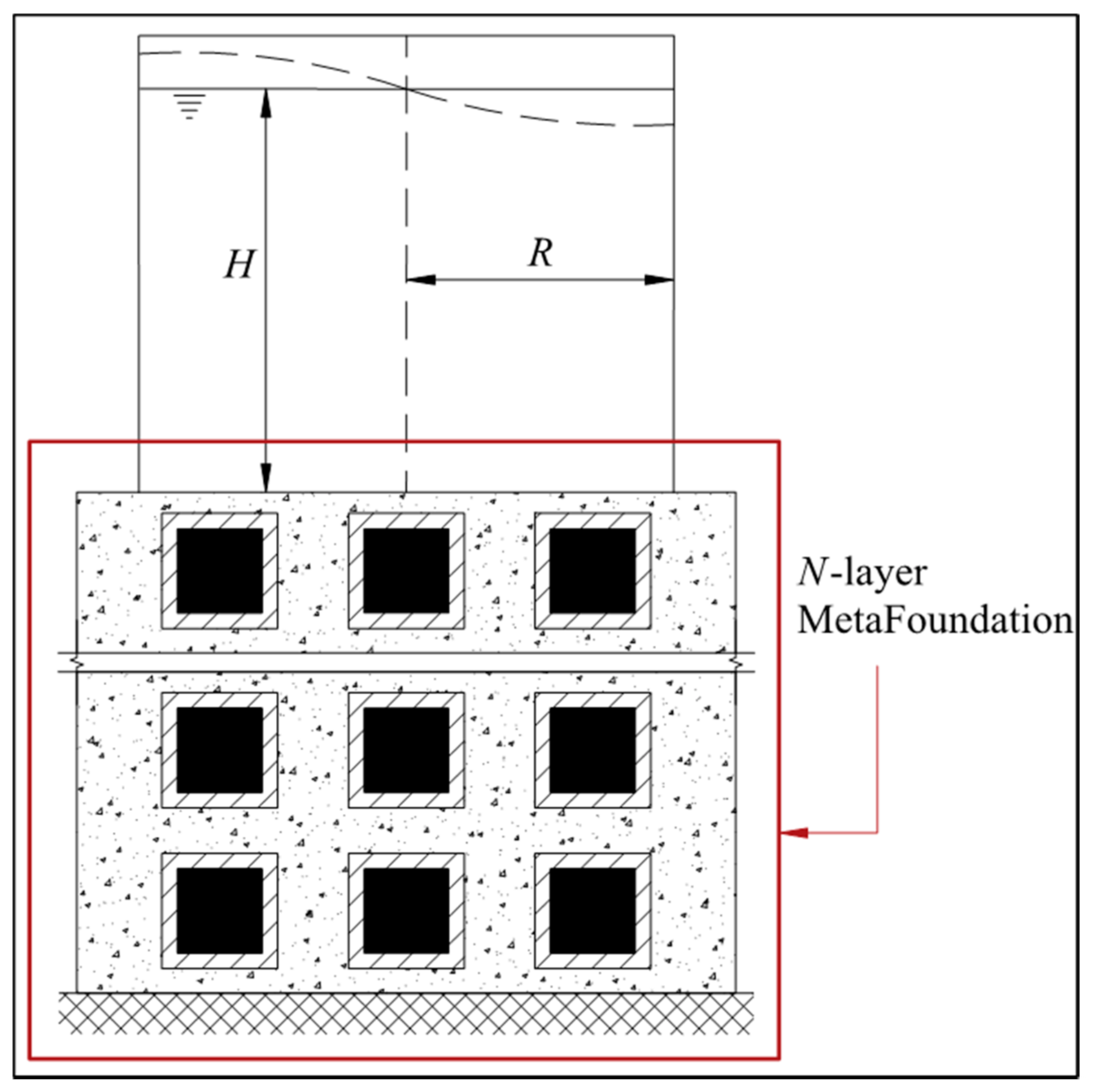
Figure 3 demonstrates a cylindrical liquid tank mounted on an
N-layer MF. The geometrical properties of the tank are the height of the liquid (
H), the thickness of the wall of the tank (
tw) and the radius of the tank (
R).
In this paper, the mass–spring model suggested by Malhotra et al. is used for the dynamic time history analysis of the liquid storage tank (
Figure 4).
The impulsive and convective masses (mi and mc) are connected to the wall of the tank by linear springs whose stiffnesses are ki and kc, respectively. The stiffness of springs is influenced by the properties of the filling fluid, the tank material, and the geometric properties of the tank. The damping coefficients corresponding to the impulsive and convective masses are shown by ci and cc, respectively.
The damping coefficient and stiffness corresponding to impulsive and convective masses are expressed as follows:
where
ζi and
ζc are the damping ratios of the impulsive and convective masses.
Ti and
Tc are natural periods corresponding to impulsive and convective responses, given by [
41]:
where
Es is the modulus of elasticity of the tank material and
ρw is the mass density of filling fluid, respectively. The ratio of impulsive and convective masses to the total mass (
mi/
m) and (
mc/
m), relative heights of impulsive and convective masses (
hi/H) and (
hc/H), and the coefficients
Ci and
Cc are suggested by Malhotra et al. [
41]. The filling fluid mass (
m) equals to
πR2Hρw.
4. Governing Equations of Motion MF-Tank System
The simplified mass–spring model of an
N-layer MF-tank system is depicted in
Figure 5.
The whole system comprises 2N degrees of freedom representing the MetaFoundation and two degrees of freedom demonstrating the convective and impulsive masses, respectively.
The governing equations of motion of the MF tank system can be written in matrix form:
where
MT,
KT, and
CT are the mass, stiffness, and damping matrices of the coupled tank system mounted on the MetaFoundation, respectively expressed by
The superscript MF and Tank stand for MetaFoundation and tank system, respectively; u is the displacement of the system relative to the ground; x2 = (u2 − u1), xi = (ui − u1), xc = (uc − u1) are displacement of internal, impulsive, and convective masses relative to the external mass, respectively. In Equation (21), the earthquake acceleration is shown by üg, and r is a column vector of one.
To obtain the time history of responses of the liquid storage tanks with MF, the governing equations of motion are derived and transferred to the first-order differential equations. Then, these equations are solved in each time step using the state-space representation and ODE15s in MATLAB programming language. The response quantities of interest are vertical displacement of the surface of the fluid (
dv), impulsive displacement (
xi), overturning moment (
M) at the top of the MF, and structural base shear of the tank (
Fs). While the impulsive displacement can be obtained directly through the solving of equations of motion, the vertical displacement of the free surface, the overturning moment at the top of the foundation, and structural base shear are calculated according to Equations (31)–(33), respectively [
8]. The overturning moment determines the generated hydrodynamic forces in the tank wall, which is proportional to the axial compressive force. The axial compressive force is the main reason of buckling of the tank walls, either in the form of elephant foot buckling or diamond shape buckling. Conversely, the vertical displacement of the free surface caused by the convective component controls the required freeboard. In the case of lack of sufficient freeboard, the tank may experience a leak of fluid, tear of the shell or break of the shell–roof connection.
where
ωc is the frequency of the convective mass (
ωc = 2π/
Tc). For simplicity and better comparison of the results, the performance index of vertical displacement of the surface of the liquid (PI
dv), the displacement of impulsive mass (PI
xi), overturning moment on the foundation (PI
M), and structural base shear (PI
Fs) are defined as the ratio of seismic responses of the liquid storage tank mounted on the MF (
dvMF,
xiMF,
MMF and
FsMF) to the corresponding responses of the tank in fixed base condition (
dvF,
xiF,
MF and
FsF), according to Equations (34)–(37). Therefore, a PI of less than one indicates that the MF is an efficient solution to improve the dynamic behaviour of liquid storage tanks. However, the performance index of more than one shows that the response is amplified due to the implementation of MF. Therefore, the MF has an adverse effect.
In addition to the time history of responses, it is interesting to evaluate the efficiency of the proposed MetaFoundation in the frequency domain through the transmission ratio (
TR) of displacement above the MF against different frequencies (
f). The transmission ratio is expressed as
In Equation (38), the amplitude of the input displacement at the bottom of the MF is shown by u0 (f), and the amplitude of the displacement measured at the top of the MF is shown by ut (f), respectively. In detail, in order to obtain the displacement transmission ratio, a harmonic displacement at various frequencies is imposed at the bottom of the foundation with amplitude u0, and the displacement response ut on the top of the foundation is observed.
5. Numerical Study
For practical applications, the periodic MetaFoundation must be constructed by available materials. In this paper, it is assumed that the foundation is made of concrete, and the heavy cores are made of steel coated by rubber. The material properties of different parts of unit cells, including modulus of elasticity and density, are listed in
Table 1.
For the preliminary time history analysis, it is assumed that the MetaFoundation comprises unit cells with dimensions of 0.305 × 0.305 × 2.0 m corresponding to the length, width, and height, respectively. In addition, the cores of unit cells have a dimension of 0.10 m. The thickness of the rubber is assumed to be 0.05 m. The damping ratios corresponding to concrete and rubber are assumed to be 5% and 30%, respectively. A dispersion analysis has been conducted to calculate the dispersion relation and stop band corresponding to an infinite unit cell. The optical and acoustic branches obtained from the dispersion analysis are illustrated in
Figure 6.
The results show that the stop band forms in the frequency range of 18.733 to 18.984 Hz, where the elastic waves cannot propagate through the MF according to the Floquet–Bloch theory. However, the obtained stop band is valid for an infinite number of unit cells. For the case of the foundation comprising finite unit cells, additional modal analysis is required to calculate the stop band.
Two different types of cylindrical tanks have been considered as case studies from [
8]. The considered tanks have different aspect ratios (height to radius). The ratio of height to the radius of the assumed tanks (
S =
H/
R) is 0.6 and 1.85, corresponding to squat and slender tanks, respectively. The filling fluid is assumed to be water, with a mass density of
ρw = 1000 kg/m
3.
Table 2 shows the geometrical properties of considered tanks. A foundation that has a square shape is considered for both squat and slender tanks. The dimension of the MF for the squat tank is assumed to be 50.0 × 50.0 m, corresponding to its width and length, respectively; for the slender tank, a MetaFoundation with 15.0 m length and width is considered. As mentioned above, the height of each layer of MF is assumed to be 2.0 m.
The natural period, relative masses, and relative heights of the simplified mass–spring model depend on the geometrical properties of the cylindrical tanks. The parameters of the equivalent mechanical model of the tank have been calculated and tabulated in
Table 3. The damping ratios of the convective (
ζc) and impulsive masses (
ζi) are assumed to be 0.5% and 2%, respectively, as suggested by [
8].
An adequate number of earthquakes should be considered for the required time history analysis to assess the efficacy of the proposed MF on the seismic responses of liquid storage tanks. Federal Emergency Management Agency (FEMA) [
42] suggested three sets of ground motions for quantifying seismic performance factors of buildings. The three sets include far-field (FF), near-fault without pulse (NF-WO Pulse), and near-fault with pulse (NF-W Pulse) ground motions. In this paper, the FF set, which comprises twenty-two pairs of records with an average moment magnitude of
Mw = 7.0, has been used. Each record has two horizontal components; therefore, the system is subjected to forty-four ground motions. All of the considered earthquakes with a distance from the fault rupture of more than 10 km were recorded on site classes C or D based on the NEHRP classification, and they do not reveal any pulse in their velocity time history. Besides, the selected excitations cover different intensities in terms of their PGA. The ground motions were downloaded from the strong ground motion database of the PEER NGA-West2 (pacific earthquake engineering research) centre. The properties of the considered earthquakes, including the station name,
Mw, PGA, and PGV, have been listed in detail in
Table 4.
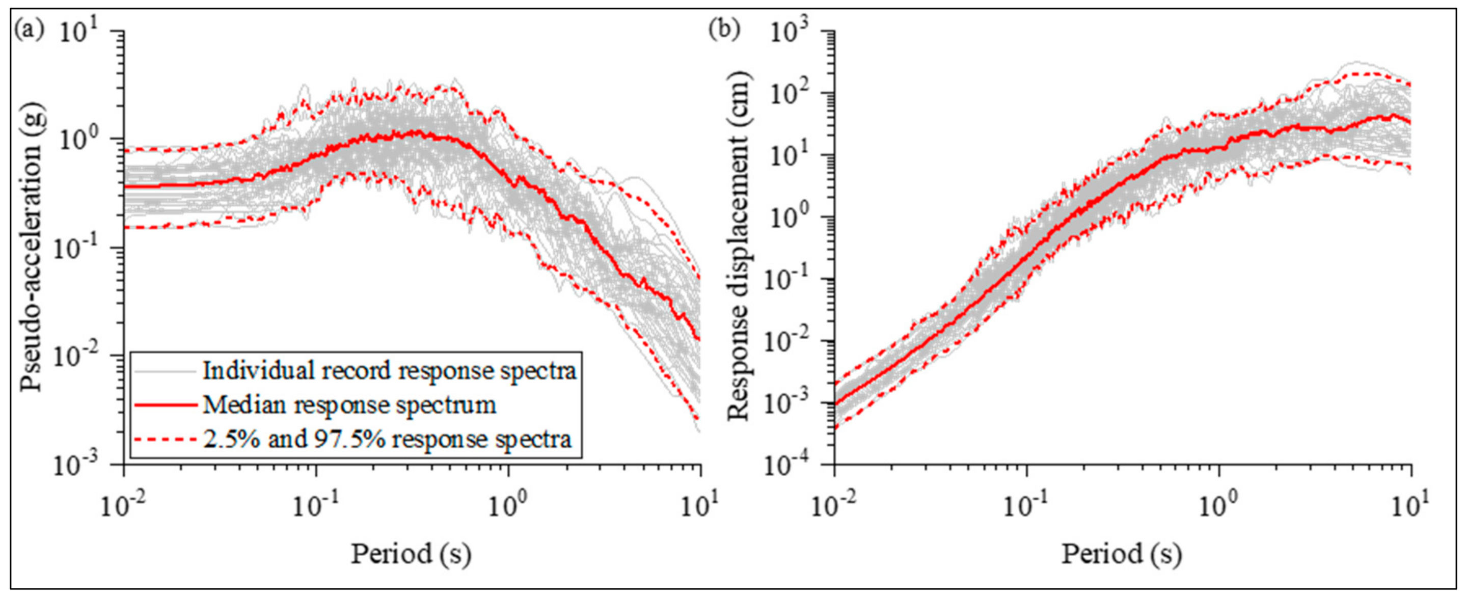
Figure 7 a,b depicts the pseudo-acceleration and spectral displacement of the selected earthquake ground motions for 2% and 0.5% damping ratios corresponding to the impulsive and convective masses, along with median as well as 2.5% and 97.5% percentile.
6. Verification
In order to verify the obtained governing equations of motion, the vertical displacement of free surface (dv) and impulsive mass displacement (xi) of both squat and slender tanks mounted on an MF with a small dimension of the core are compared with corresponding responses in fixed base conditions. To that end, it is assumed that the core has a dimension of 0.001, 0.001, and 0.001 m corresponding to width, length, and height, respectively, and the thickness of the soft layer is 0.001 m. These small dimensions have been assigned to the core and the soft layer to avoid difficulties during solving of the governing equations of motion. It is expected that this MetaFoundation behaves as a traditional foundation made by concrete, and the resonators have no significant influence on the seismic responses of tanks.
Figure 8 compares the time history of the vertical displacement of the free surface as well as the impulsive displacement of both squat and slender tanks subjected to the Friuli, A-TMZ270 earthquake. The obtained responses verify the governing equations of motion and the accuracy of responses of liquid storage tanks with MF. The maximum difference between the responses is found to be less than 1%.
7. Results and Discussions
7.1. Effect of MetaFoundation
To evaluate the influence of the proposed MetaFoundation in the time domain, the time transient analysis is performed under selected ground motions. The seismic responses of liquid storage tanks mounted on MF are compared with the corresponding responses in fixed base condition. The parameters of the MF are described in the previous section.
Figure 9 shows the time history of seismic responses of considered tanks under ABBAR—L, Manjil earthquake.
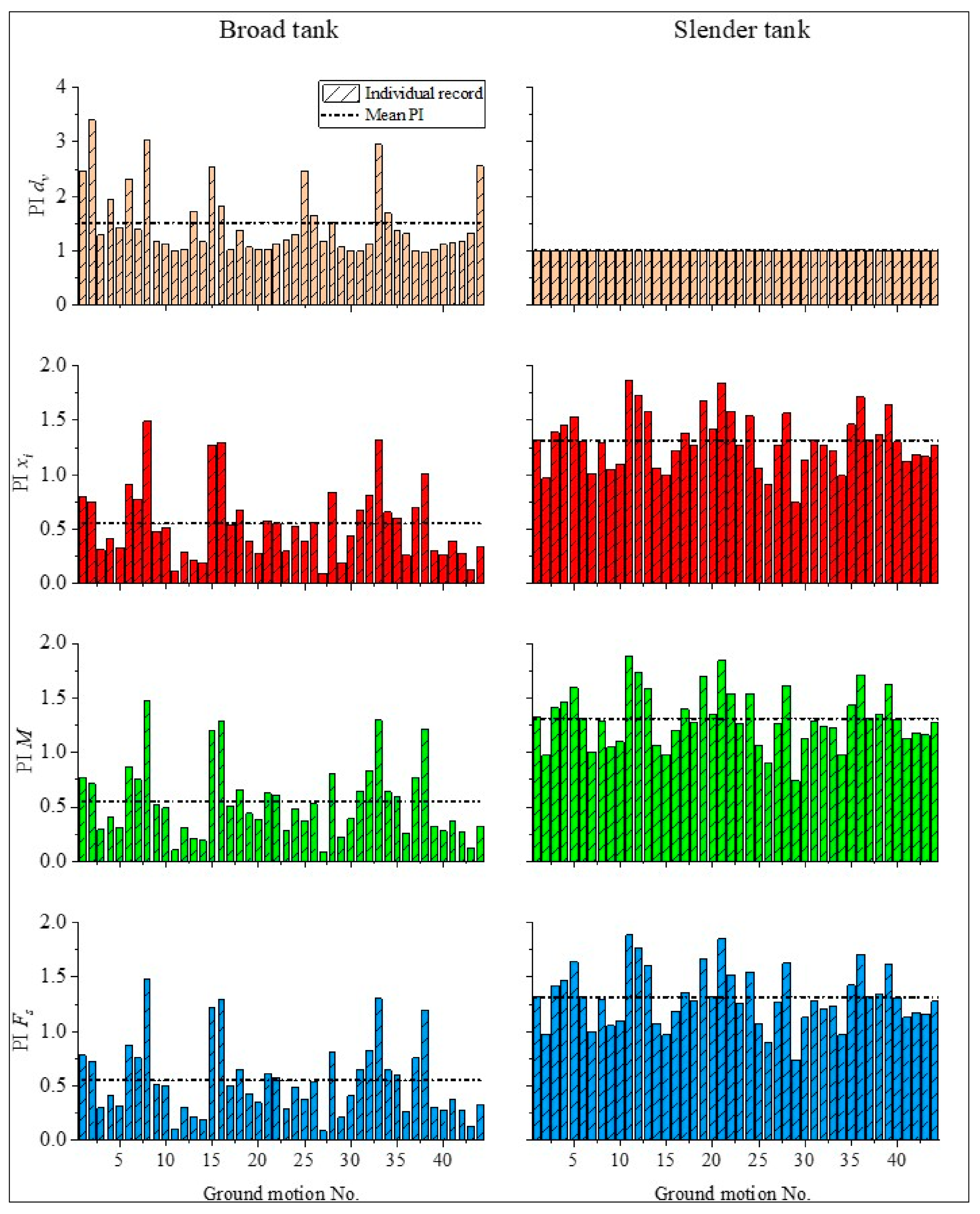
The seismic responses are depicted for both squat and slender tanks in fixed base condition and mounted on MF, respectively. The performance index of seismic responses of the selected liquid storage tank tanks subjected to various ground motions is depicted in
Figure 10. According to the obtained responses, two different trends were observed for the performance of the MF on the seismic responses of squat and slender tanks.
First, in the squat tanks, it is observed that the displacement of the impulsive mass, overturning moment on top of the foundation, and base shear have been reduced in most cases due to the implementation of the MF. The mean performance index of the displacement of impulsive mass, overturning moment on the foundation, and base shear are 0.551, 0.551, and 0.551, illustrating that the MF reduces the input excitation. Therefore, the use of the MF in the squat tank is an effective solution to improve its dynamic behaviour. The best performance of the MF was observed when the system was subjected to G03000, Loma Prieta ground motion in which the PI of the displacement of the impulsive mass, overturning moment on the MF, and base shear equalled 0.091, 0.09, and 0.091, respectively. However, a performance index of more than one is seen in some cases. For example, a PI equal to 1.491, 1.480, and 1.476 for the displacement of impulsive mass, the overturning moment on the foundation and base shear was observed when the system was excited by HEC090, showing that the MF increases the responses compared to fixed base condition. This is attributed to the fact that the performance of MF highly depends on the frequency content of input earthquake ground motion as well as the stop band. According to
Figure 11, it is seen that in some frequency ranges, the TR is magnified. This illustrates that the amplitude of the input wave will be intensified, and therefore, the responses of liquid storage tanks are increased compared to the fixed base condition. The reduction of the overturning moment leads to a decrease in the axial demand in the tank wall, which is the main reason for the buckling of the tank wall. Hence, the more economical and reliable design of the tank is achievable by the use of MF.
Conversely, it is seen that the MF increases the vertical displacement of the free surface of the liquid. The mean performance index of the vertical free surface displacement is 1.5. Therefore, it is vital to consider a more freeboard to avoid the disrupting consequences corresponding to vertical displacement of the free surface.
Second, with reference to
Figure 10, one can conclude that the displacement of impulsive mass, overturning moment on the foundation, and base shear in the slender tank are magnified in most cases. The mean PI of the impulsive displacement, overturning moment, and base shear in the slender tank are 1.315, 1.315, and 1.35, respectively. Therefore, it can be concluded that the MF has an adverse effect on the seismic responses of the slender liquid storage tank. The best performance of the MF is observed under the ABBAR—L, Manjil earthquake in which the PI corresponding to the displacement of impulsive mass, overturning moment on top of foundation, and base shear are 0.742, 0.742, and 0.740, respectively. In terms of the vertical displacement of the free surface, it is seen that the MF has no significant effect. As is seen in
Figure 10, the PI of the vertical displacement of the free surface approximately equals one for all of the earthquake ground motions.
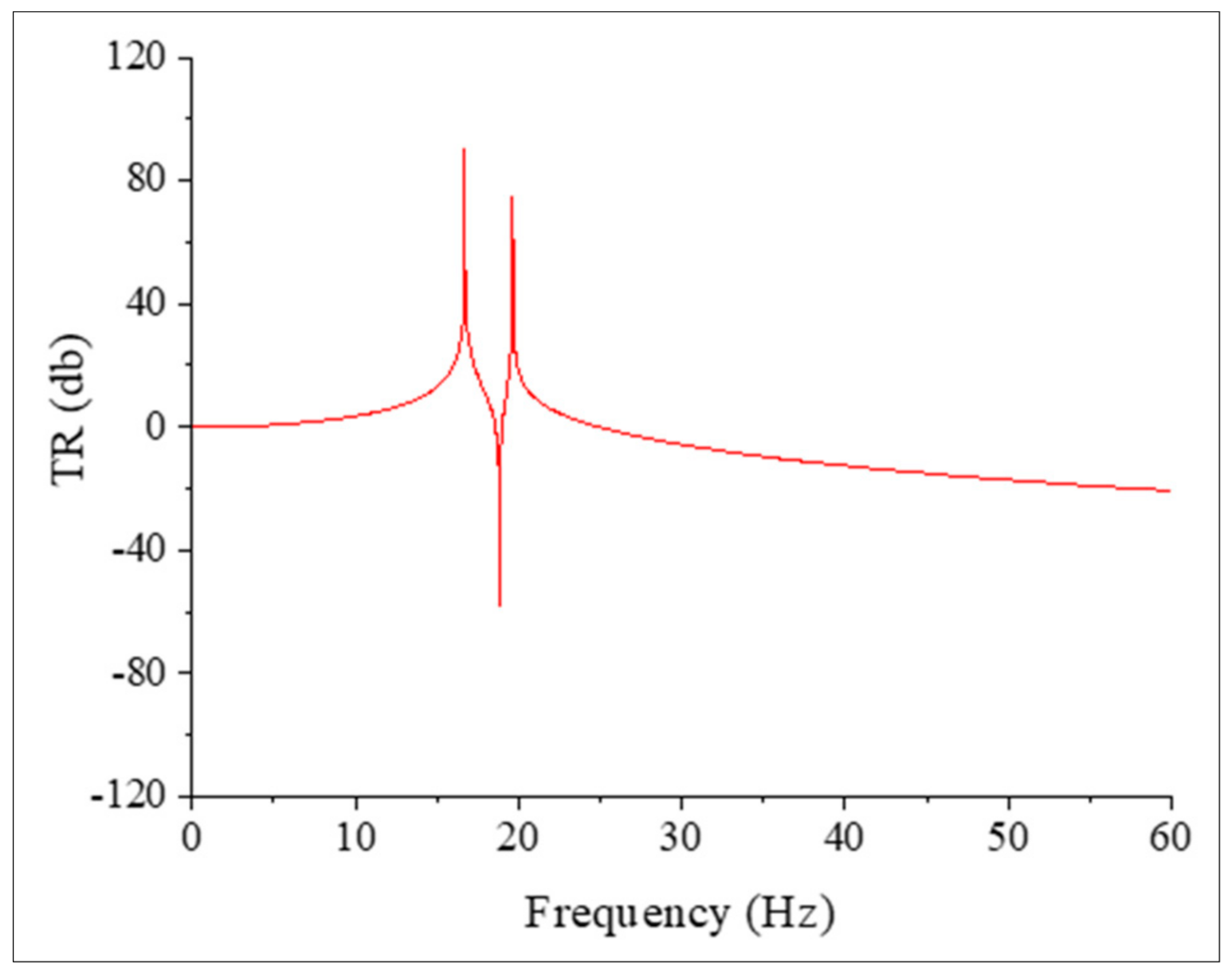
To demonstrate the filtering effect of the MF, the TR above the MF in the absence of the liquid storage tank is demonstrated in
Figure 11.
A TF equal to zero implies that the displacement output on the top of the foundation equals the input displacement induced at the bottom of the foundation. After that, the TR corresponding to the regions of less than zero indicates that the amplitude of the output displacement is less than the amplitude of the input displacement. This is due to the fact that the incident wave is blocked and cannot pass through the MF. Conversely, when the amplitude of the input displacement increases, the value of TR becomes more than zero; hence, the MF has an adverse effect. With reference to
Figure 11, an amplification area is seen for the frequency region below 18.733 Hz, followed by an attenuation region from 18.733 to 18.984 Hz where the wave cannot propagate throughout the MF. The second attenuation zone is seen for frequencies over 22.4 Hz. Based on the obtained responses, the MF reduces the amplitude of waves with frequencies falling in the stop band. Since an earthquake is a random phenomenon with a wide range of frequencies, and its frequency content cannot be predetermined, the effectiveness of MF is limited to those ranges of frequencies which it is designed for.
7.2. Effect of the Frequency Content of the Excitation
To evaluate the influence of the characteristics of the input excitation, the PI of the seismic responses of both squat and slender tanks are depicted in
Figure 12 against the predominant frequency of the considered earthquake. The predominant frequency is determined through the signal processing of considered earthquake ground motions and by selecting the maximum spectral acceleration occurring in their acceleration response spectra.
Besides, a linear regression line is plotted to observe the overall trend of the responses over the frequencies of the considered earthquake ground motions. Generally, it is seen that the PI of the displacement of the impulsive mass, overturning moment, and base shear of the squat tank is less than one for all of the ground motions with the predominant frequency higher than the frequency corresponding to impulsive mass. Conversely, both a PI of less and more than one were observed for the aforementioned responses when the system was subjected to ground motions with the predominant frequency lower than the frequency of the impulsive mass. In the case of the slender tank, the PI of more than one was observed for the impulsive displacement, overturning moment, and base shear when the system was subjected to excitations with the predominate frequency lower than the impulsive frequency. Besides, for those earthquakes with a predominant frequency higher than the impulsive mass frequency, a PI of less and more than one can be observed.
7.3. Effect of Number of Layers
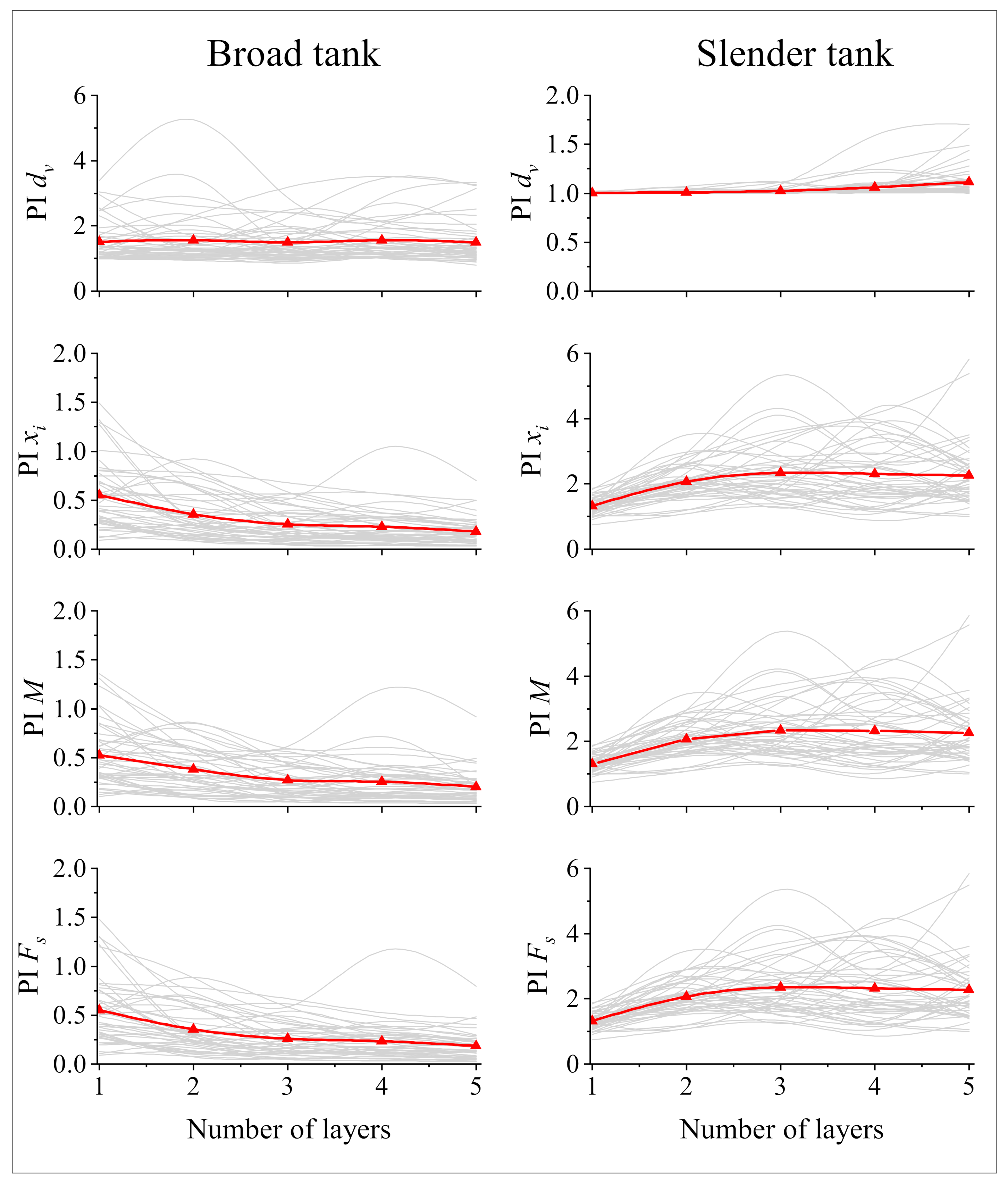
In this section, the effect of the number of layers of MetaFoundation on the seismic responses of squat and slender liquid storage tanks is investigated. The height of each layer is kept constant at 2.0 m, and the properties of unit cells are the same as those mentioned in the previous sections. For the required analysis, five types of MF with one, two, three, four, and five layers are considered. For a better comparison of the obtained results, the numerical results provided in terms of performance index under various considered ground motions are shown in
Figure 13.
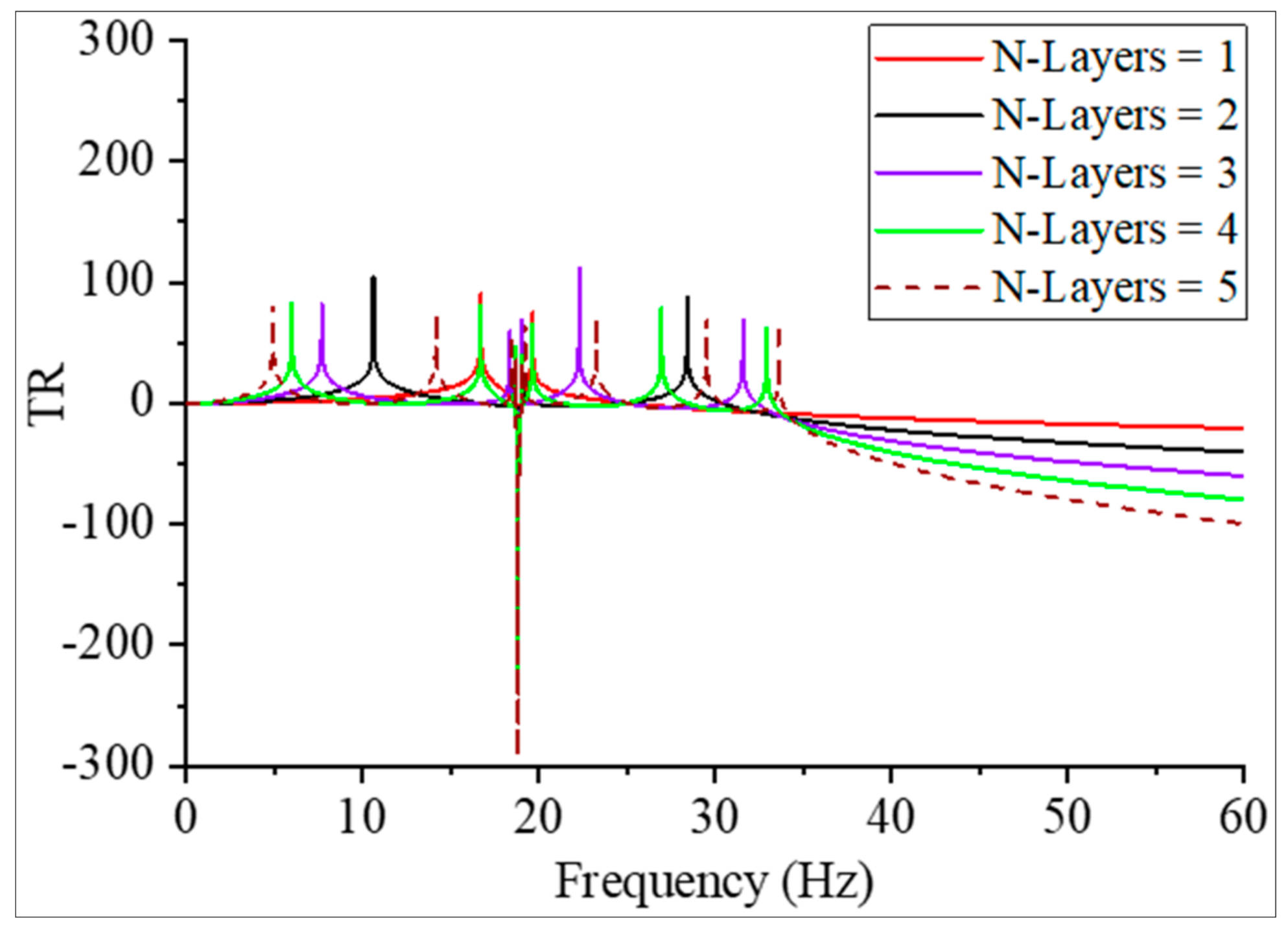
In the case of the squat tank, one can see that the performance index of the displacement of impulsive mass, overturning moment on the foundation, and structural base shear decreases as the number of layers. Therefore, the more layers there are, the more reduction in the responses. Conversely, for the slender tank, it is seen that as the number of layers of MetaFoundation increases, the displacement of the impulsive mass, overturning moment on the MF, and base shear significantly increase. According to the TR shown in
Figure 14, the boundary of the stop band becomes steeper when the number of layers of MF increases, leading to more attenuation of the input energy in this region. Conversely, for other regions other than the stop band, the TR increases, causing the intensify of the input energy. Therefore, the seismic responses of the squat tank are decreased, and those of the slender tank are magnified.
In terms of the vertical displacement of the free surface, it is observed that the mean PI of vertical displacement of the free surface remains constant for the different number of layers in the squat tank. However, a slight increase is observed in the slender tank.
7.4. Effect of Rubber Thickness (tr)
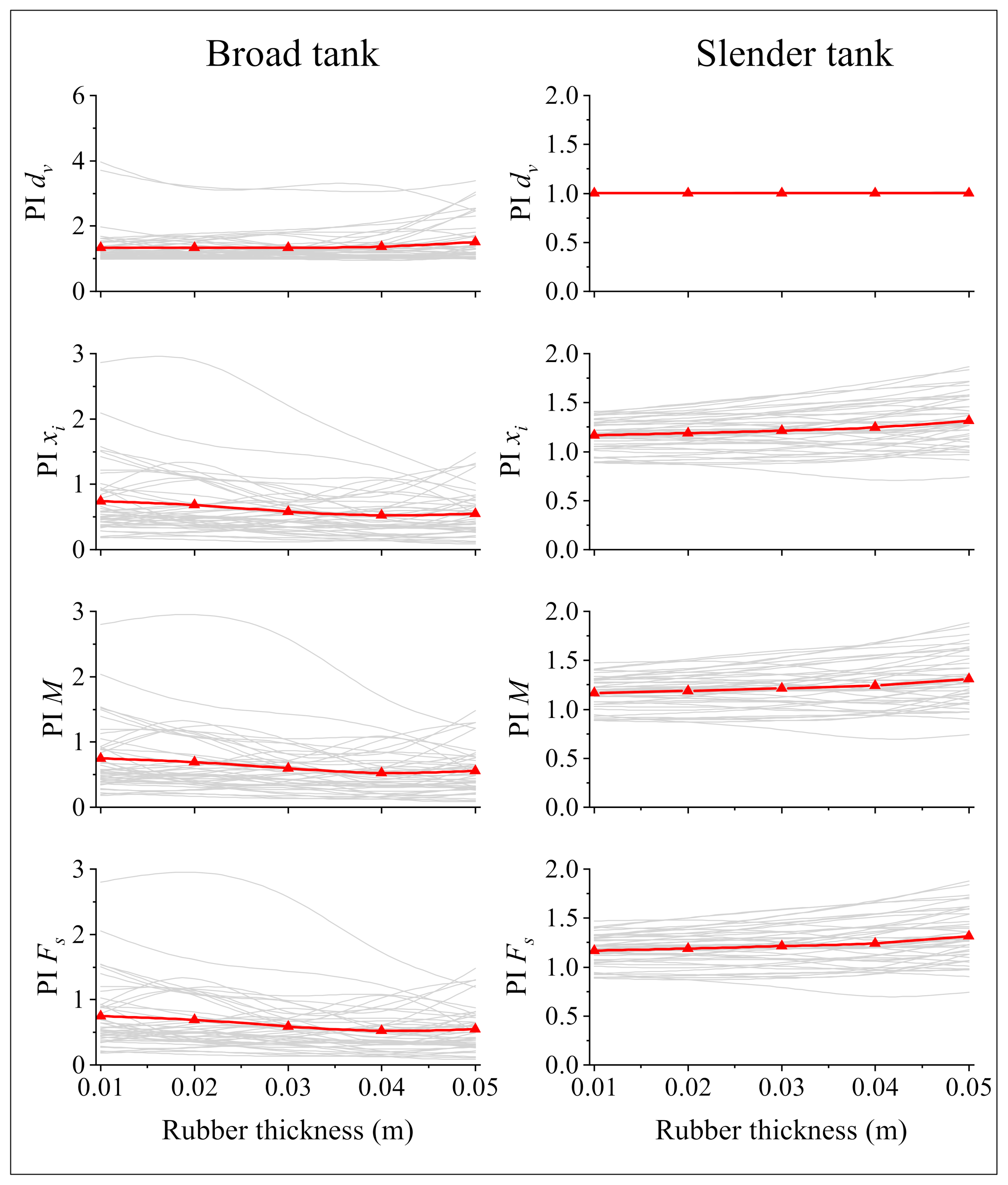
The effect of rubber thickness on the seismic responses of liquid storage tanks is investigated here. Five different rubber thicknesses,
tr = 0.01, 0.02, 0.03, 0.04, 0.05 m were considered for the models. The dimension of the unit cell and the heavy core is the same with other sections. The obtained responses of squat and slender tanks subjected to various ground motions are illustrated in
Figure 15.
From the obtained response, one can observe that the free vertical surface displacement (dv) is not sensitive to rubber thickness (tr), and these responses are almost constant for various values of rubber thickness. Conversely, other seismic responses are changed with the change in rubber thickness. The obtained results show that as the thickness of rubber increases, the displacement of the impulsive mass (xi), overturning moment on the MF, and base shear (M and Fs) decreases in the squat tank, leading to the improvement in the performance of the liquid storage tank. Conversely, a slight increase is observed in the impulsive mass displacement, overturning moment, and base shear of the slender tank. However, a fluctuation trend is seen for some earthquakes in both squat and slender tanks. This is attributed to the frequency content of earthquake ground motion, which affects the performance of MF.
7.5. Effect of Damping of Soft Material
In this section, the effect of damping of soft material on the seismic response of considered liquid storage tanks is investigated. In order to study the effect of damping, five different damping ratios of
ζSM are considered as 0.05, 0.1, 0.15, 0.2, 0.25 and 0.3, respectively. The dimension of unit cell, heavy core, and thickness of soft material are assumed to be the same with the previous sections.
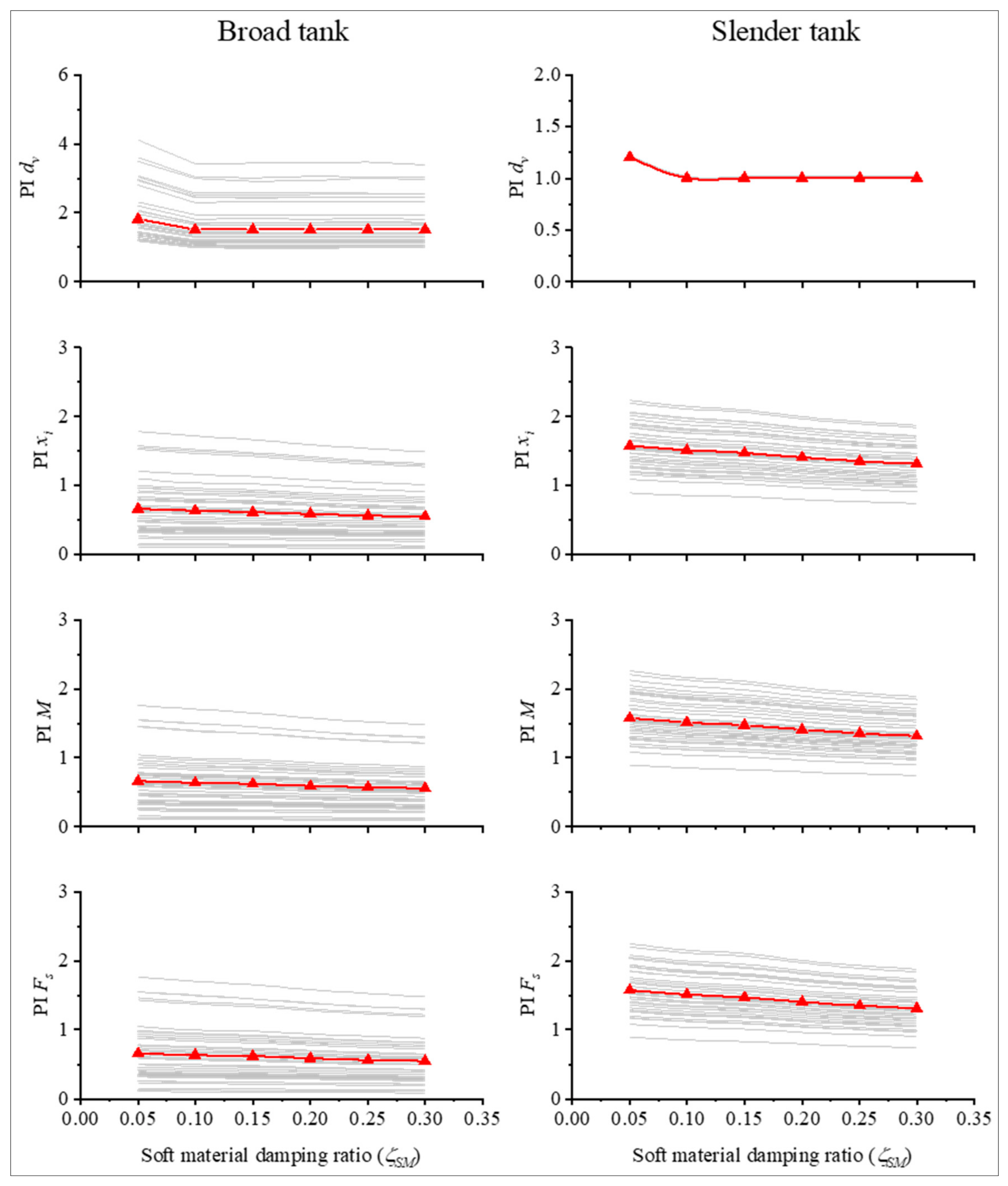
Figure 16 illustrates the effect of damping ratios on the maximum responses of both liquid storage tanks.
The results obtained from time history analysis indicate that the damping ratios of soft material affects the maximum responses of structures. The more damping ratios there are, the more the impulsive mass displacement (xi) becomes reduced. As a result of such reduction, the overturning moment (M) recorded on the MF and the structural base shear (Fs) are decreased. However, it is seen that the damping ratio of soft material has no significant effect on the vertical displacement of free surface (dv).
8. Conclusions
This paper evaluates the effectiveness of a novel foundation called MetaFoundation (MF) on the seismic response of liquid storage tanks. The MF comprises concrete and cubic shape steel coated with rubber as a soft layer. The concept of the MF is based on the finite locally resonant metamaterials, which produce a stop band to avoid the propagation of waves. The obtained results indicate that the MF has the capability to reduce the seismic response of squat liquid storage tanks, such as displacement of the impulsive mass, overturning moment, and base shear. Conversely, the obtained performance indexes indicate that the use of MF will lead to an increase in the seismic responses of the slender tank.
The effects predominant frequency of earthquakes, the number of layers of metamaterial, rubber thickness, and damping ratios of soft material were studied. The results confirm that as the number of metamaterials increases, more reductions can be observed in the TR of the stop band; therefore, the displacement of the impulsive mass, overturning moment on the top of the foundation, and base shear of squat tank decreases. However, the displacement of free vertical surface displacement was not significantly affected. Besides, the obtained responses show that the rubber thickness has an insignificant effect on the vertical displacement of the free surface of the squat tank, while other responses such as impulsive mass displacement, overturning moment, and structural base shear reduce when the rubber thickness increases. Furthermore, it was observed that the use of MF amplified the seismic responses of the slender tank. The results indicated that as the number of layers of metamaterial increases, the results become more reduced.
Author Contributions
Conceptualization, M.F. and M.I.K.; methodology, M.F. and M.I.K.; software, M.F.; validation, M.F., M.I.K. and P.S.; formal analysis, M.F.; investigation, M.F.; resources, P.S.; data curation, M.F.; writing—original draft preparation, M.F.; writing—review and editing, P.S.; visualization, M.I.K.; supervision, M.I.K.; project administration, M.I.K.; funding acquisition, P.S. All authors have read and agreed to the published version of the manuscript.
Funding
No specific funding was received for this article.
Institutional Review Board Statement
Not applicable.
Informed Consent Statement
Not applicable.
Data Availability Statement
The data presented in this study are available on request from the corresponding author. The data are not publicly available.
Conflicts of Interest
The authors declare no conflict of interest.
References
- Cooper, T.W. A Study of the Performance of Petroleum Storage Tanks during Earthquakes, 1933–1995; US National Institute of Standards and Technology: Gaithersburg, MD, USA, 1997.
- Hamdan, F. Seismic behaviour of cylindrical steel liquid storage tanks. J. Constr. Steel Res. 2000, 53, 307–333. [Google Scholar] [CrossRef]
- Lee, C.-B.; Lee, J.-H. Nonlinear Dynamic Response of a Concrete Rectangular Liquid Storage Tank on Rigid Soil Subjected to Three-Directional Ground Motion. Appl. Sci. 2021, 11, 4688. [Google Scholar] [CrossRef]
- Zhao, Y.; Li, H.-N.; Zhang, S.; Mercan, O.; Zhang, C. Seismic Analysis of a Large LNG Tank Considering Different Site Conditions. Appl. Sci. 2020, 10, 8121. [Google Scholar] [CrossRef]
- Zhang, R.; Chu, S.; Sun, K.; Zhang, Z.; Wang, H. Effect of the Directional Components of Earthquakes on the Seismic Behavior of an Unanchored Steel Tank. Appl. Sci. 2020, 10, 5489. [Google Scholar] [CrossRef]
- Jing, W.; Feng, H.; Cheng, X. Dynamic responses of liquid storage tanks caused by wind and earthquake in special environment. Appl. Sci. 2019, 9, 2376. [Google Scholar] [CrossRef] [Green Version]
- Zhang, S.; Zhang, R.; Zhao, Z. Demand-Based Optimal Design of Storage Tank with Inerter System. Shock. Vib. 2017, 2017, 2956153. [Google Scholar] [CrossRef] [Green Version]
- Malhotra, P.K. New method for seismic isolation of liquid-storage tanks. Earthq. Eng. Struct. Dyn. 1997, 26, 839–847. [Google Scholar] [CrossRef]
- Shrimali, M.; Jangid, R. A comparative study of performance of various isolation systems for liquid storage tanks. Int. J. Struct. Stab. Dyn. 2002, 2, 573–591. [Google Scholar] [CrossRef]
- Shrimali, M.; Jangid, R. Seismic response of liquid storage tanks isolated by sliding bearings. Eng. Struct. 2002, 24, 909–921. [Google Scholar] [CrossRef]
- Shekari, M.; Khaji, N.; Ahmadi, M. A coupled BE–FE study for evaluation of seismically isolated cylindrical liquid storage tanks considering fluid–structure interaction. J. Fluids Struct. 2009, 25, 567–585. [Google Scholar] [CrossRef]
- Shekari, M.; Khaji, N.; Ahmadi, M. On the seismic behavior of cylindrical base-isolated liquid storage tanks excited by long-period ground motions. Soil Dyn. Earthq. Eng. 2010, 30, 968–980. [Google Scholar] [CrossRef]
- Abalı, E.; Uckan, E. Parametric analysis of liquid storage tanks base isolated by curved surface sliding bearings. Soil Dyn. Earthq. Eng. 2010, 30, 21–31. [Google Scholar] [CrossRef]
- Jadhav, M.B.; Jangid, R.S. Response of Base-Isolated Liquid Storage Tanks. Shock. Vib. 2004, 11, 276030. [Google Scholar] [CrossRef]
- Farajian, M.; Khodakarami, M.I.; Kontoni, D.-P.N. Evaluation of Soil-Structure Interaction on the Seismic Response of Liquid Storage Tanks under Earthquake Ground Motions. Computation 2017, 5, 17. [Google Scholar] [CrossRef] [Green Version]
- Karkabadi, A.; Khodakarami, M.I.; Farajian, M. Seismic Response of Steel Frame by Considering Soil-Structure Interaction under Seismic Sequence. J. Struct. Constr. Eng. 2021, 8, 66–86. [Google Scholar]
- Bagheri, S.; Farajian, M. The effects of input earthquake characteristics on the nonlinear dynamic behavior of FPS isolated liquid storage tanks. J. Vib. Control 2018, 24, 1264–1282. [Google Scholar] [CrossRef]
- Cheng, X.; Jing, W.; Chen, J.; Zhang, X. Pounding Dynamic Responses of Sliding Base-Isolated Rectangular Liquid-Storage Structure considering Soil-Structure Interactions. Shock. Vib. 2017, 2017, 8594051. [Google Scholar] [CrossRef] [Green Version]
- Bagheri, S.; Farajian, M. Seismic Response of Base Isolated Liquid Storage Tanks under Near Fault Ground Motions. Athens J. Technol. Eng. 2016, 3, 153–161. [Google Scholar] [CrossRef]
- Tsiavos, A.; Sextos, A.; Stavridis, A.; Dietz, M.; Dihoru, L.; Alexander, N.A. Experimental investigation of a highly efficient, low-cost PVC-Rollers Sandwich (PVC-RS) seismic isolation. Structures 2021, 33, 1590–1602. [Google Scholar] [CrossRef]
- Tsiavos, A.; Markic, T.; Schlatter, D.; Stojadinovic, B. Shaking table investigation of inelastic deformation demand for a structure isolated using friction-pendulum sliding bearings. Structures 2021, 31, 1041–1052. [Google Scholar] [CrossRef]
- Mead, D. Wave propagation in continuous periodic structures: Research contributions from Southampton, 1964–1995. J. Sound Vib. 1996, 190, 495–524. [Google Scholar] [CrossRef]
- Sigalas, M.; Kushwaha, M.S.; Economou, E.N.; Kafesaki, M.; Psarobas, I.E.; Steurer, W. Classical vibrational modes in phononic lattices: Theory and experiment. Z. Krist.-Cryst. Mater. 2005, 220, 765–809. [Google Scholar] [CrossRef]
- Bao, J.; Shi, Z.; Xiang, H. Dynamic responses of a structure with periodic foundations. J. Eng. Mech. 2011, 138, 761–769. [Google Scholar] [CrossRef]
- Sun, F.; Xiao, L.; Bursi, O.S. Optimal design and novel configuration of a locally resonant periodic foundation (LRPF) for seismic protection of fuel storage tanks. Eng. Struct. 2019, 189, 147–156. [Google Scholar] [CrossRef]
- Sun, F.; Xiao, L. Bandgap characteristics and seismic applications of inerter-in-lattice metamaterials. J. Eng. Mech. 2019, 145, 04019067. [Google Scholar] [CrossRef]
- Farajian, M.; Sharafi, P.; Kildashti, K. The influence of inter-module connections on the effective length of columns in multi-story modular steel frames. J. Constr. Steel Res. 2021, 177, 106450. [Google Scholar] [CrossRef]
- Alembagheri, M.; Sharafi, P.; Rashidi, M.; Bigdeli, A.; Farajian, M. Natural dynamic characteristics of volumetric steel modules with gypsum sheathed LSF walls: Experimental study. Structures 2021, 33, 272–282. [Google Scholar] [CrossRef]
- Jia, G.; Shi, Z. A new seismic isolation system and its feasibility study. Earthq. Eng. Eng. Vib. 2010, 9, 75–82. [Google Scholar] [CrossRef]
- Mitchell, S.J.; Pandolfi, A.; Ortiz, M. Metaconcrete: Designed aggregates to enhance dynamic performance. J. Mech. Phys. Solids 2010, 65, 69–81. [Google Scholar] [CrossRef]
- Dertimanis, V.K.; Antoniadis, I.A.; Chatzi, E.N. Feasibility analysis on the attenuation of strong ground motions using finite periodic lattices of mass-in-mass barriers. J. Eng. Mech. 2016, 142, 04016060. [Google Scholar] [CrossRef]
- Maleki, M.; Khodakarami, M. Feasibility analysis of using MetaSoil scatterers on the attenuation of seismic amplification in a site with triangular hill due to SV-waves. Soil Dyn. Earthq. Eng. 2017, 100, 169–182. [Google Scholar] [CrossRef]
- Basone, F.; Wenzel, M.; Bursi, O.S.; Fossetti, M. Finite locally resonant Metafoundations for the seismic protection of fuel storage tanks. Earthq. Eng. Struct. Dyn. 2019, 48, 232–252. [Google Scholar] [CrossRef]
- Aguzzi, G.; Kanellopoulos, C.; Wiltshaw, R.; Craster, R.V.; Chatzi, E.N.; Colombi, A. Octet lattice-based plate for elastic wave control. Sci. Rep. 2022, 12, 1088. [Google Scholar] [CrossRef]
- Cheng, Z.; Shi, Z. Novel composite periodic structures with attenuation zones. Eng. Struct. 2013, 56, 1271–1282. [Google Scholar] [CrossRef]
- Institute, A.P. Seismic Design of Storage Tanks-Appendix E, Welded Steel Tanks for Oil Storage; API Publishing Services: Washington, DC, USA, 2007. [Google Scholar]
- American Society of Civil Engineers. Minimum Design Loads and Associated Criteria for Buildings and Other Structures; American Society of Civil Engineering & Structural Engineering Institute: Reston, VA, USA, 2016. [Google Scholar]
- European Committee for Standardization. Eurocode 8: Design of Structures for Earthquake Resistance-Part 4: Silos, Tanks and Pipelines; European Committee for Standardization: Brussels, Belgium, 2006. [Google Scholar]
- Housner, G.W. The dynamic behavior of water tanks. Bull. Seismol. Soc. Am. 1963, 53, 381–387. [Google Scholar] [CrossRef]
- Haroun, M.A.; Housner, G.W. Seismic design of liquid storage tanks. J. Tech. Counc. ASCE 1981, 107, 191–207. [Google Scholar] [CrossRef]
- Malhotra, P.K.; Wenk, T.; Wieland, M. Simple procedure for seismic analysis of liquid-storage tanks. Struct. Eng. Int. 2000, 10, 197–201. [Google Scholar] [CrossRef] [Green Version]
- FEMA. Quantification of Building Seismic Performance Factors; US Department of Homeland Security, FEMA: Washington, DC, USA, 2009.
Figure 1.
Three-dimensional view of the proposed MetaFoundation.
Figure 1.
Three-dimensional view of the proposed MetaFoundation.
Figure 2.
Simplified mass–spring model of an MF.
Figure 2.
Simplified mass–spring model of an MF.
Figure 3.
A liquid storage tank mounted on an MF.
Figure 3.
A liquid storage tank mounted on an MF.
Figure 4.
Simplified model of the liquid storage tank.
Figure 4.
Simplified model of the liquid storage tank.
Figure 5.
Simplified mass–spring model of the liquid storage tank mounted on an N-layer MF.
Figure 5.
Simplified mass–spring model of the liquid storage tank mounted on an N-layer MF.
Figure 6.
Dispersion analysis of considered unit cell.
Figure 6.
Dispersion analysis of considered unit cell.
Figure 7.
(a) Pseudo-acceleration and (b) response displacement spectra of considered earthquake ground motions.
Figure 7.
(a) Pseudo-acceleration and (b) response displacement spectra of considered earthquake ground motions.
Figure 8.
Verification of the obtained responses subjected to the Friuli, A-TMZ270 earthquake.
Figure 8.
Verification of the obtained responses subjected to the Friuli, A-TMZ270 earthquake.
Figure 9.
Time history of responses of squat and slender tank subjected to ABBAR—L, Manjil ground motion for w/o and w MF.
Figure 9.
Time history of responses of squat and slender tank subjected to ABBAR—L, Manjil ground motion for w/o and w MF.
Figure 10.
Performance index (PI) of various seismic responses of squat and slender tanks.
Figure 10.
Performance index (PI) of various seismic responses of squat and slender tanks.
Figure 11.
TR of the displacement above the MF.
Figure 11.
TR of the displacement above the MF.
Figure 12.
Effect of the frequency content of input earthquake on performance index of seismic responses of squat and slender tanks.
Figure 12.
Effect of the frequency content of input earthquake on performance index of seismic responses of squat and slender tanks.
Figure 13.
Effect of the number of layers on various seismic responses of squat and slender liquid storage tanks.
Figure 13.
Effect of the number of layers on various seismic responses of squat and slender liquid storage tanks.
Figure 14.
Effect of the number of layers on the TR on top of the foundation.
Figure 14.
Effect of the number of layers on the TR on top of the foundation.
Figure 15.
Effect of thickness of rubber (tr) on various seismic responses of squat and slender liquid storage tanks.
Figure 15.
Effect of thickness of rubber (tr) on various seismic responses of squat and slender liquid storage tanks.
Figure 16.
Effect of soft material damping ratio on the seismic response of squat and slender liquid storage tanks.
Figure 16.
Effect of soft material damping ratio on the seismic response of squat and slender liquid storage tanks.
Table 1.
Material properties of a unit cell.
Table 1.
Material properties of a unit cell.
| Part Name | Material | Modulus of Elasticity, E (GPa) | Density, ρ (kg/m3) |
|---|
| matrix | concrete | 24.85 | 2400 |
| soft material | rubber | 0.000137 | 1300 |
| core | steel | 210 | 7850 |
Table 2.
Geometrical properties of the selected tanks used as case studies.
Table 2.
Geometrical properties of the selected tanks used as case studies.
| Tank Type | H (m) | R (m) | tw (m) |
|---|
| Squat | 14.6 | 24.4 | 0.0203 |
| Slender | 11.3 | 6.1 | 0.0058 |
Table 3.
Resultant parameters of the equivalent mechanical model for the selected squat and slender tanks.
Table 3.
Resultant parameters of the equivalent mechanical model for the selected squat and slender tanks.
| Tank Type | mc/m | mi/m | hc/H | hi/H | Cc (s/m0.5) | Ci | Tc (s) | Ti (s) |
|---|
| Squat | 0.608 | 0.392 | 0.557 | 0.400 | 1.65 | 7.08 | 8.15 | 0.253 |
| Slender | 0.245 | 0.755 | 0.727 | 0.444 | 1.48 | 6.07 | 3.66 | 0.157 |
Table 4.
Selected earthquakes for time history analysis.
Table 4.
Selected earthquakes for time history analysis.
| Record Pair | Earthquake | Year | Station | Mw | Component 1 | Component 2 | PGA (g) | PGV (cm/s) |
|---|
| 1 | Northridge | 1994 | Beverly Hills-Mulhol | 6.7 | MUL009 | MUL279 | 0.52 | 63 |
| 2 | Northridge | 1994 | Canyon Country-WLC | 6.7 | LOS000 | LOS270 | 0.48 | 45 |
| 3 | Duzce, Turkey | 1999 | Bolu | 7.1 | BOL000 | BOL090 | 0.82 | 62 |
| 4 | Hector Mine | 1999 | Hector | 7.1 | HEC000 | HEC090 | 0.34 | 42 |
| 5 | Imperial Valley | 1979 | Delta | 6.5 | H-DLT262 | H-DLT352 | 0.35 | 33 |
| 6 | Imperial Valley | 1979 | El Centro Array # 11 | 6.5 | H-E11140 | H-E11230 | 0.38 | 42 |
| 7 | Kobe, Japan | 1995 | Nishi-Akashi | 6.9 | INIS000 | NIS090 | 0.51 | 37 |
| 8 | Kobe, Japan | 1995 | Shin-Osaka | 6.9 | SHI000 | SHI090 | 0.24 | 38 |
| 9 | Kocaeli, Turkey | 1999 | Duzce | 7.5 | DZC180 | DZC270 | 0.36 | 59 |
| 10 | Kocaeli, Turkey | 1999 | Acrelik | 7.5 | ARC000 | ARC090 | 0.22 | 40 |
| 11 | Landers | 1992 | Yermo Fire Station | 7.3 | YER270 | YER360 | 0.24 | 52 |
| 12 | Landers | 1992 | Coolwater | 7.3 | CLW-LN | CLW-TR | 0.42 | 42 |
| 13 | Loma Prieta | 1989 | Capitola | 6.9 | CAP000 | CAP090 | 0.53 | 35 |
| 14 | Loma Prieta | 1989 | Gilroy Array #3 | 6.9 | G03000 | G03090 | 0.56 | 45 |
| 15 | Manjil, Iran | 1990 | Abbar | 7.4 | ABBAR--L | ABBAR--T | 0.51 | 65 |
| 16 | Superstition Hills | 1987 | El Centro Imp. Co. | 6.5 | B-ICC000 | B-ICC090 | 0.36 | 46 |
| 17 | Superstition Hills | 1987 | Poe Road (temp) | 6.5 | B-POE270 | B-POE360 | 0.45 | 36 |
| 18 | Cape Mendocino | 1992 | Rio Dell Overpass | 7.0 | RIO270 | RIO360 | 0.55 | 44 |
| 19 | Chi-Chi, Taiwan | 1999 | CHY101 | 7.6 | CHY101-E | CHY101-N | 0.44 | 115 |
| 20 | Chi-Chi, Taiwan | 1999 | TCU045 | 7.6 | TCU045-E | TCU045-N | 0.51 | 39 |
| 21 | San Fernando | 1971 | LA-Hollywood stor | 6.6 | PEL090 | PEL180 | 0.21 | 19 |
| 22 | Friuli, Italy | 1976 | Tolmezzo | 6.5 | A-TMZ000 | A-TMZ270 | 0.35 | 31 |
| Publisher’s Note: MDPI stays neutral with regard to jurisdictional claims in published maps and institutional affiliations. |
© 2022 by the authors. Licensee MDPI, Basel, Switzerland. This article is an open access article distributed under the terms and conditions of the Creative Commons Attribution (CC BY) license (https://creativecommons.org/licenses/by/4.0/).


