Abstract
Motivated by the fact that electrical transients are rather fast compared with mechanical response, the traditional cascade control structure constituted by the inner current and outer speed loops is usually employed in the permanent magnet synchronous motors (PMSMs) servo control community. According to the above-mentioned time-scale characteristic of the PMSMs drive systems, this technique addresses the problems of the non-cascade sliding mode control (SMC) strategy for the surface-mounted PMSMs. Firstly, by appropriately introducing the singular perturbation theory, the corresponding mathematical equations are modeled as a singular perturbation system. Meanwhile, a composite sliding mode surface is constructed based on the Lyapunov equation, such that the system stability can be also guaranteed. Then, according to the exponential reaching law, a standard non-cascade SMC law is designed. Furthermore, an optimal nonlinear function-based tracking differentiator (TD) is presented to smooth the reference velocity value, while providing differential signals. As a result, a novel TD-based SMC strategy is synthesized by incorporating a nonlinear function, thus improving the inherent chattering phenomenon. Finally, a surface-mounted PMSM servo system is performed to illustrate the advantages and effectiveness of the proposed approaches. The main contribution of this paper is to present an alternative non-cascade SMC framework based on the singular perturbation approach, which provides a novel control structure for a PMSM speed regulation system.
1. Introduction
As an important electromagnetic device, the permanent magnet synchronous motors (PMSMs) are usually characterized by many excellent features such as high efficiency, large torque/inertia ratio, and maintenance-free capability [1]. Meanwhile, with the development of power electronics and the increasing requirements of higher performance indices, the speed regulation systems have been extensively receiving much more attention in practical industrial applications [2]. For example, a nonlinear fast dynamic terminal sliding mode control (SMC)-based maximum power point tracking strategy was presented in a wind energy conversion system, where equipped with a permanent magnet synchronous generator [3]. On the other hand, the multi-objective optimization techniques of the low-speed permanent magnet motors were presented in [4], while the low-speed high-torque PMSM was employed in a direct-driven mining scraper conveyor transmission system [5]. On the contrary, four high-speed PMSMs with different rotor topologies were comparatively designed and analyzed in details [6], which were aimed at driving the air compressor of a fuel cell vehicle.
In the past decades, numerous literatures have been reported to develop the powerful approaches for the PMSMs drive systems (see [7,8,9,10,11,12,13,14,15,16,17,18] and the references therein). It should be emphasized that the advanced nonlinear control technologies can greatly improve the system performances and robustness against internal parametric perturbations and external load disturbances, simultaneously. With the series structure, an improved model predictive control (MPC) method was proposed in [7], thus improving the control performance under the conventional finite control set MPC strategy. The robust control methodology was employed in the design of disturbance observer-based feedforward and feedback controllers [8], and thus a two degree of freedom (DOF) composite speed control framework was synthesized. The discrete-time active disturbance rejection control (ADRC) method was presented to suppress the disturbances [9], where incorporated the repetitive controller and operated in parallel with the extended state observer (ESO). In order to decrease the approximate error of the speed loop, a second-order model description was proposed in [10], and then a composite controller comprised of the SMC feedback law and ESO-based feedforward compensation was conducted. Among the above-mentioned nonlinear control strategies, the SMC technique is famous as its particularly strong robustness, and has attracted much more attention in recent years [11]. The traditional feedback control approaches usually suffer from the contradiction between the rapidity and overshoot, and thus the composite nonlinear feedback (CNF) technique was introduced in the designed integral SMC speed controller [12]. An ESO-based continuous terminal SMC speed regulation problem was addressed in [13], the proposed composite SMC method obtained the fast convergence and satisfactory tracking performances. By taking the time-varying disturbances into account, the generalized proportional integral observer (GPIO) was constructed to estimate various disturbances, whose estimation values were incorporated into the continuous SMC law. Based on the novel reaching law, an extended sliding mode disturbance observer-based SMC speed controller was implemented in [15], thus compensating for the adverse influence of the lumped uncertainties. It is worth mentioning that the above-mentioned approaches mainly concentrate on the design and analysis of the speed controller [10,11,12,13,14,15], thus improving the PMSM drive system performance. In addition, the traditional cascade control structure is employed in these researches, where a PI-type controller will usually act as the inner current loop. A speed current single loop control scheme was proposed to a PMSM drive system [16], which also involved the nonlinear disturbance observer. The single loop non-cascade control simplifying the system structure was presented in [17], where the dual disturbance observers-based feedforward and the integral SMC feedback were individually designed and eventually synthesized. However, the presented non-cascade control structure still requires a PI controller for the direct axis current regulation [16,17]. Based on the feedback linearization technology and nonlinear disturbance observer, the composite single-loop terminal SMC structure was investigated to realize the speed and the current tracking regulations, simultaneously, thus replacing the conventional cascade control framework [18]. Inspiring by the above discussions, the investigation about non-cascade SMC design for PMSMs has the important significance.
For the large-scale industrial processes, there usually exist small time constants, parasitic inductances and capacitance, thus separating the eigenvalues of system state space variables into the different regions [19]. As a result, the multi-time-scale plants can be modeled as the singular perturbation systems (SPSs), while the powerful singular perturbation theory is employed to controller design and stability analysis [20]. The advanced heavy water reactor characterized by 38 slow, 35 fast, and 17 fastest state variables was presented in [21], which was eventually modeled as a three-time-scale SPS. An extended high gain observer-based output feedback control strategy for the nonlinear SPSs was addressed [22], and the single link manipulator with several uncertain terms were discussed, respectively. In addition, the continuous SMC for compliant robot arms was formulated as a SPS [23], which was comprised by the slow rigid robot and a fast series elastic actuator dynamics. For an electric motor, the singular perturbation theory-based rigorous analysis for the augmented system was presented in [24], and the dual PI observers-based cascade control scheme was conducted in details. By constructing the disturbance observer and modeling the PMSM as a dual-time-scale SPS [25], the non-cascade SMC strategy was exhibited. It can be concluded from the reported literatures that the singular perturbation theory is a powerful tool to design and analyze the controlled system, and by modeling the PMSM as an SPS is still an open research field.
Motivated by the above-mentioned researches, this paper considers the problems of the non-cascade SMC for surface-mounted PMSMs speed regulation systems. By selecting the singular perturbation parameter as the electrical time constant, a SPS is eventually modeled. According to eigenvalue placement technique, the exact decoupled subsystem dynamics are stable, thus resulting a composite sliding mode surface. Then, a standard non-cascade SMC law is designed based on the exponential reaching law. Furthermore, a novel tracking differentiator (TD)-based SMC is synthesized by incorporating a nonlinear function. Finally, the advantages and effectiveness of the proposed approaches are illustrated by research results. The contributions of this study can be summarized as follows. (1) The singular perturbation decomposition approach-based composite sliding mode surface is constructed, which involves the Lyapunov equation and rigorous theoretical analyses. (2) An alternative non-cascade SMC strategy has been proposed in detail, where an optimal nonlinear function based-TD is presented to arrange the transition dynamic. (3) The conventional signum function is replaced by a nonlinear function, thus improving the inherent chattering phenomenon in the SMC community.
The rest of this paper is organized as follows. In Section 2, the singular perturbation-based modeling and preliminaries are presented. The main results are given in Section 3, including the design and analysis of the sliding mode surface and non-cascade SMC laws in details. Some simulation results are exhibited in Section 4. Section 5 concludes this paper.
2. System Modeling and Preliminaries
The classical mathematical model of a surface-mounted PMSM can be established in terms of the two-phase synchronous rotating orthogonal reference coordinate system [14], which is comprised by electrical dynamics
and mechanical dynamic equation
where is the stator inductance; and denote d and q axes stator currents, respectively; and represent d and q axes stator voltages, respectively; is stator resistance; is the flux linkage of permanent magnets; J is the moment of the rotational inertia; is the electromagnetic torque coefficient, and is the number of pole pairs; F is the viscous friction coefficient; represents the load torque disturbance; and are electrical and mechanical angular velocities, respectively, which satisfying .
It is worth mentioning that the nonlinear back electromotive forces (EMFs) produced by products of electrical angular velocity with d and q axes stator currents and , increasing the complexity of controller design and analysis. In order to eliminate the adverse effect of the above-mentioned back EMFs, we can actively compensate their influences through the feedforward channel, and thus the following simplified linear electrical dynamics can be easily obtained:
where and are the nominal control inputs in the absence of and , respectively, which also satisfying the following relationship:
The objective of this study is to design the novel SMC laws and for a surface-mounted PMSM, such that can be regulated to its desired signal in the presences of the external disturbances. To this end, we can introduce the following velocity tracking error:
Substituting the velocity tracking error (5) into the mechanical dynamic Equation (2) and electrical dynamics (3), yields
where and represent the mechanical and q axis disturbances, respectively.
To our best knowledge, the electrical transients (namely, currents and ) are rather faster comparing with the mechanical response (i.e., angular velocity ) [10], which can also be characterized by the following inequality:
where and denote the electrical and mechanical time constants, respectively.
According to the above relationship, it can be concluded that the surface-mounted PMSM is an typical dual-time-scale system. As a result, by selecting the singular perturbation parameter , the Equation (6) can be modeled as the following SPS:
where the system matrices and parameters are presented as follows.
where is the system state vector, the separation degree between the slow mode and fast-time state variables is indicated by the small parameter ; denotes the disturbances, which satisfying ( is the upper bound), and represents the Euclidean norm.
Remark 1.
It can be concluded from time constant difference (7) that the surface-mounted PMSM speed regulation system is characterized by the obvious dual-time-scale, which can be formulated as a typical SPS (8). This study presents an alternative way to build the mathematical model, and thus the non-cascade control scheme can be subsequently performed.
3. Singular Perturbation Approach-Based SMC
In this section, we will firstly construct a novel composite sliding mode surface based on the exact decoupled subsystems, where involves singular perturbation decomposition method. And then, the sliding mode controller is presented, while the reachability condition is guaranteed. Finally, the TD-based eventual SMC strategy for a surface-mounted PMSM is synthesized in details.
3.1. Composite Sliding Mode Surface Design and Stability Analysis
In the subsection, we will mainly concern on the design and analysis of a novel composite sliding mode surface, which is integrated by decoupled subsystem dynamics. For the purpose of satisfying individual desired performances, the Lyapunov equations are involved for singular perturbation decomposition-based exact subsystems.
For convenience, we can obtain the following assumption and lemmas motivated by [20]:
Assumption 1.
The matrix pairs (, ) and (, ) are controllable, where
Lemma 1.
According to eigenvalue placement technique, it is reasonable to assume that there exist state feedback gain matrices and , thus stabilizing the slow and fast subsystems, respectively. That is to say, their system matrices and will be arbitrarily assigned to become Hurwitz stable. As a result, the following nominal control law can be synthesized:
where .
Proof.
For the SPS (8), if we do not take the disturbances into account, the corresponding nominal system can be obtained. According to the quasi-steady theory, one can firstly derive the following quasi-steady solution by setting :
where the subscript ”s” represents the slow variable components of the corresponding physical quantities, and .
Based on (12), the original full-order SPS (8) can be approximately equivalent by the following slow-time subsystem:
and the fast-time subsystem, which is as follows.
where the subscript “f” denotes the fast variable components of the above-mentioned corresponding physical quantities, which satisfying and , respectively.
According to Assumption 1, one can design the following slow-time control effort:
which is employed to stabilize the slow-time subsystem (13), resulting in
where represent the eigenvalue.
Obeying the same procedure as for the slow-time scale subsystem, we can also find the following fast-time control law:
which will stabilize the fast-time subsystem (14), namely the closed-loop system matrix is asymptotically stable.
Finally, we can synthesize the nominal controller by combining the individual slow-time and fast-time linear feedback control law (15) and (17), which is as follows.
Substituting quasi-steady solution (12) into (18) leads to the following nominal control law for the full-order SPS (8) in the original coordinate:
This completes the proof. □
Lemma 2
(Singular Perturbation Approach). Incorporating an extra control input into the nominal control law (11) results in the composite control law . Substituting the actual into the original full-order system (8), and introducing the following Chang transformation:
where φ is the completely decoupled system state vector comprising by the new slow mode ξ and fast dynamics η; , and ; is the identity matrix with appropriate dimensions; and are the corresponding solutions of the following algebraic equations:
where , , and ; and ; is the zero matrix with appropriate dimensions.
As a result, the exactly complete decoupling subsystems with the principal diagonal form can be eventually derived as
where the corresponding matrices are listed as follows
Remark 2.
According to the algebraic Equation (21), we can easily obtain that and , resulting in the initial matrix values and , respectively, where represent the ε-dependent infinitesimal value. In addition, by employing the fixed-point recursive algorithm, one can calculate the solutions of the above formulations, which are as follows: and , where and are the iteration numbers (non-negative integers) for and , respectively.
For the presented exact decoupled SPSs (22), we have the following theorem.
Theorem 1.
Under Lemmas 1 and 2, the diagonal system matrix in (22) is asymptotically stable. To this end, there exists a positive definite symmetric matrix satisfying the following Lyapunov equation for the any given positive definite symmetric matrix :
Proof.
First of all, we can easily obtain the following closed-loop system matrix from the reduced-order subsystem dynamic :
Because the feedback gain only contributes to the fast-time states, which can be ignored in (25). Meanwhile, substituting into the above equation, it can be concluded that
which indicates that . Furthermore, for the any given positive constant , there exists a satisfying the following Lyapunov equation:
On the other hand, for the fast-time dynamic in (22), the corresponding system matrix is presented as follows.
It can be concluded form Lemma 1 that the matrix is asymptotically stable, and thus there exists a small such that the eigenvalues of have negative real parts for all . Therefore, for the any given positive definite symmetric matrix , there exists a positive definite symmetric matrix satisfying the following Lyapunov equation:
As a result, according to the well-known separation principle, the closed-loop system matrix is asymptotically stable. At the same time, according to individual Lyapunov Equations (27) and (29), it can be summarized that there exists the following Lyapunov equation for system (22):
where the diagonal matrix and , respectively.
This completes the proof. □
Remark 3.
The above-mentioned theorem indicates that the eigenvalues of the diagonal system matrix can be approximately equivalent to the eigenvalue combinations of the corresponding slow-subsystem matrix and fast-subsystem matrix . According to Assumption 1, both of their matrix pairs can be stabilized based on the eigenvalue placement technique. As a result, the corresponding subsystem dynamics are asymptotically stable, simultaneously.
According to Theorem 1, we can conclude that the singular perturbation decomposition method-based exact decoupled system state vector are asymptotically stable with satisfying the Lyapunov Equation (24). In order to guarantee the desired system performance, we construct a novel composite sliding mode surface associating with the system dynamics (22), which results the following theorem.
Theorem 2.
Based on the Lyapunov approach, a novel composite sliding mode surface is constructed for original SPS (8), which is as follows
Meanwhile, the system (22) is asymptotically stable on the above designed sliding mode surface during the sliding mode.
Proof.
First of all, we can construct the following sliding mode surface:
When the sliding mode is arrived, the equivalent control method will be commonly adopted to analyze the system stability. As a result, the following formulation will be obtained:
Introducing the following Lyapunov function:
Calculating the time-derivative of the , leads to
According to the Lyapunov Equation (30) and the formulation (33), it can be concluded that the system (22) is asymptotically stable, when the system state trajectory is driven and strictly restricted onto the sliding mode surface (32).
On the other hand, based on the Chang transformation matrix presented in (20), we can rewrite the sliding mode surface (32) into the original coordinate, which is shown as (31).
This completes the proof. □
3.2. Sliding Mode Controller Design and Reachability Analysis
In this subsection, we will mainly focus on the design of the sliding mode controller, while the reachability condition is guaranteed.
According to the commonly employed exponential reaching law [11], one can design the following sliding mode controller:
where and , respectively; and are the exponential and switching gains, respectively; ; ; denotes the signum function.
For the the proposed SMC (36), we have the following theorem.
Theorem 3.
Under the designed SMC law (36), the system state variables will be globally driven onto the above-mentioned composite sliding mode surface in a finite time. Namely, the reachability condition can be guaranteed.
Proof.
First of all, it can be easily obtained the following formulation from (31):
On the other hand, it can be concluded from (8) that
And then, taking the time-derivative of the in terms of , yields
Introducing the following Lyapunov function:
Calculating the time-derivative of the , leads to
where . The inequality (41) imply that , while is a positive scalar function. According to the Lyapunov stability theory, it can be concluded that the composite sliding mode surface (37) can be attained in a finite time.
This completes the proof. □
Remark 4.
Although the Lyapunov equation-based composite sliding mode surface satisfying the stable condition is constructed in terms of the state space φ, it is recommended to be transformed into the original coordinate. Because the state variables ψ can be directly measured and calculated, the design and analysis of the SMC law is implemented (36).
3.3. TD-Based Eventual SMC for a PMSM Servo System
In this subsection, the TD-based eventual SMC strategy for a surface-mounted PMSM will be synthesized in details.
It is worth mentioning that the presented disturbances in (9) can be rewritten as
where can be defined as the nominal disturbances in the absence of external load torque .
For the above-mentioned , we can incorporate it into the SMC law (36), if the favorable differential signal is provided. In addition, it is an effective way to improve the tracking performance by arranging a smooth transition dynamic for reference velocity [26]. To these ends, an optimal nonlinear function-based TD is employed in this study, which is as follows:
where and are the tracking estimation values for and its differential signal , respectively; is the discrete step; is the estimation error; r is the velocity factor; h is the filtering factor; The nonlinear function is presented as
On the other hand, it is well known that the discontinuous function is the essential reason to cause the chattering phenomenon, which is a challenging problem in SMC community. In order to address the existing issue, a nonlinear function is adopted as
where is the input variable, and is the design parameter to be determined later.
For the above introduced function , if we constrain the corresponding output within the bound value , resulting in , where is the saturation function.
By taking the above-mentioned improvements into account, the TD-based eventual SMC can be synthesized as follows.
where .
As a result, the corresponding schematic block diagrams of the different non-cascade SMC strategy for a PMSM regulation system are individually shown as Figure 1, which are distinguished with each other by using the abbreviations of “SMC” and “TD-SMC”, respectively.
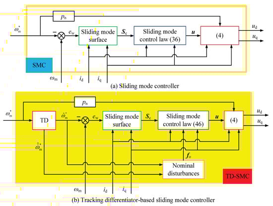
Figure 1.
The schematic block diagrams of the different non-cascade SMC strategy.
Remark 5.
There are three differences between the presented SMC (36) and the novel TD-based SMC (46): (1) The presented TD-based transition dynamic is employed to design the control law, rather than the actual reference velocity . (2) The nominal disturbances are adopted to reduce the switching gain value γ, which is inspired by the upper bound relationship . (3) A nonlinear function is introduced to replace the signum function, thus improving the chattering phenomenon. Such configurations can promote the regulation performances for a PMSM drive system, which can be demonstrated by the subsequent results.
Remark 6.
This study proposes the singular perturbation approach-based non-cascade SMC strategy for a surface-mounted PMSM drive system, which is symbolized by Figure 1. It should be emphasized that the conventional cascade control structure is popular among the PMSMs speed regulation systems [10,11,12,13,14,15], which is usually comprised of the inner current and outer speed loops, respectively. Although some recent literature has presented a non-cascade control framework for a PMSM servo system [16], a PI controller for the d axis current loop is still required [17]. It can be concluded that the non-cascade control for PMSM is of great important significance. By employing the singular perturbation theory, a complete non-cascade SMC approach that obviously different from the traditional vector control method developed in this paper, whose effectiveness and feasibility are demonstrated by the following researches.
In the last, the whole block control structure for a PMSM servo system is shown as Figure 2. In Figure 2, a DC voltage source with is firstly provided as the power supply, and then the three-phase inverter drives the PMSM based on the pulse signals. Meanwhile, the three-phase currents , and are individually measured by the sensors, which are transformed into the d and q axes stator currents and by the well-known Clark and Park components (where the and are intermediate current values without using the angle information). On the other hand, according to the mechnical encoder, the motor speed and electrical angle will be calculated, simultaneously. Therefore, the different non-cascade control SMC strategy shown as Figure 1 can be implemented. Eventually, the controller output and will be transformed into and based on the Park inverse module, thus generating the modulating waves for the well-known space vector pulse width modulation (SVPWM) element. Finally, the close-loop control scheme for a PMSM servo system is realized.
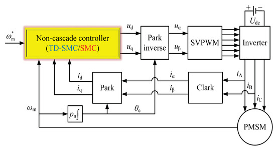
Figure 2.
The whole block control structure for a PMSM servo system.
4. Simulation Results
A surface-mounted PMSM is considered in this section to illustrate the effectiveness and advantages of the presented approach, whose specification parameters has been exhibited in Table 1. The subsequent research results are conducted on the well-known Matlab/Simulink platform, which involves the discrete-time model. According to the corresponding parameters, one can calculate the individual time constants as and , which indicates the relationship (7) is strictly guaranteed.

Table 1.
Specification parameters of a surface-mounted PMSM.
Then, the singular perturbation parameter is determined as . In addition, the matrices presented in Assumption 1 are as follows.
According to Lemma 1, one can artificially assign the individual eigenvalues of the corresponding slow and fast subsystem matrices as and , respectively. The above-mentioned eigenvalues can be realized by employing the following state feedback gain matrices:
In order to illustrate the effectiveness of the fixed-point recursive algorithm presented in Remark 2, we introduce the norm-variables and (both of their initial values are set as 0.1) to denote the recursive errors between the current and last iteration values. In the procedure of program realization, the iteration operations will be immediately finished if the above-mentioned norm-variables are greater than . As a result, the corresponding iteration procedures are exhibited as Figure 3.
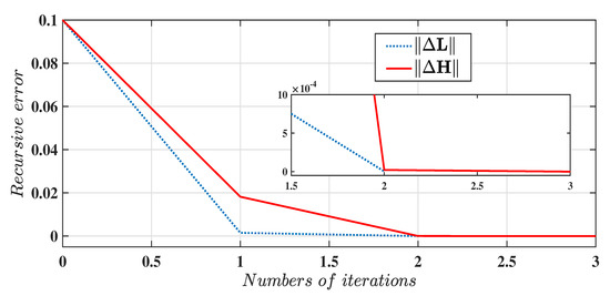
Figure 3.
The recursive procedures of solving the transformation matrices and .
It can be concluded form Figure 3 that the transformation matrix calculation results will gradually converge their actual values when the iteration numbers are and , respectively. Eventually, the following transformation matrices can be obtained:
Thus, the system matrix and control input matrix presented in (23) can be obtained according to the above calculation results, which are as follows.
Furthermore, it can found that , which are very approximate to the above-mentioned subsystem eigenvalues and .
By choosing the matrix as , we can obtain the solution of the Lyapunov Equation (24), which is as follows.
which indicates that , which are all positive, thus guaranteeing the Theorem 1.
Finally, the corresponding coefficients for constructing the sliding mode surface (37) and the different SMC laws are individually calculated, which are as follows.
On the other hand, in order to implement the whole block control scheme for a PMSM servo system shown as Figure 2, the DC-link capacitor voltage is set as , while the carrier frequency is determined as . Meanwhile, the associated design parameters of the different control laws are listed in Table 2, where their output magnitude values are limited as .
Table 2.
Associated design parameters of the different control laws.
For the purpose of realizing the TD-based eventual SMC law (46), we carefully explore the tracking performance by employing different velocity factor, as shown in Figure 4.
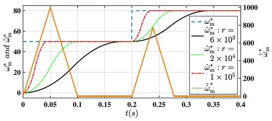
Figure 4.
The tracking performance and differential signal of the presented TD.
It should be emphasized that the response time of the favourable transition dynamic can be adjusted by determining an appropriate r, while the corresponding high quality differential signal is subsequently obtained. On the other hand, for the presented nonlinear function , its characteristic curves with respect to are comprehensively compared with different , which are shown as Figure 5.
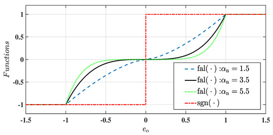
Figure 5.
The characteristic curves of and .
It can be seen form Figure 5 that the function is smoother than along with the input variable , thus improving the chattering phenomenon and the speed regulation performances, simultaneously. According to the above-mentioned discussions, the important parameters are selected as and , respectively, which are also listed in the above-presented Table 2.
In order to validate the effectiveness and advantages of the presented approaches, the reference velocity value is set as a step signal, which changes from 50 rad/s (initial value) to 80 rad/s at 0.2 s. In addition, a sudden load torque 1.5 is employed at 0.3 s, which is aimed at illustrating the speed regulation system robustness against the external disturbances. As a result, the velocity responses under the different non-cascade SMC strategies are shown in Figure 6, while the regulation errors are characterized by Figure 7.

Figure 6.
The velocity response with different non-cascade control strategies.
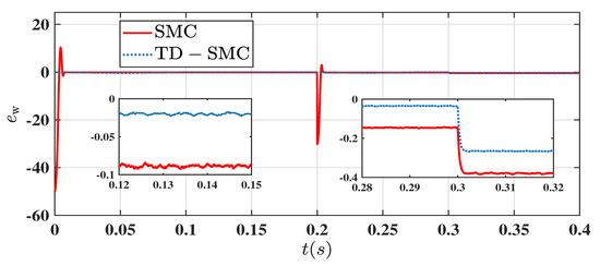
Figure 7.
The characteristic curves of the regulation errors.
It can be concluded from Figure 6 and Figure 7 that the presented TD-SMC (46) possesses a smaller steady-state regulation error than that of SMC (36). In addition, benefitting from the constructed TD (44), the velocity response performance is characterized by no obvious overshoot. Meanwhile, by combining Figure 4 and Figure 6, it can be founded that the arranged transition dynamic has about 0.1 s time delay when the velocity factor is determined as . It is worth mentioning that, for the above-mentioned reference signal , which can be quickly and accurately tracked by the speed regulation system under the proposed TD-SMC strategy. In summary, the satisfactory system performance can be guaranteed based on the presented approach.
5. Conclusions
This paper has investigated the problem of the non-cascade SMC strategy for the surface-mounted PMSMs speed regulation systems with disturbances. A singular perturbation decomposition approach is firstly presented to construct the composite sliding surface, while the fixed-point recursive algorithm is employed to calculate the solutions of transformation matrices. By incorporating the TD and a nonlinear function into the designed SMC law, the eventual TD-based SMC strategy has been presented in details. The simulation results demonstrate that the TD can arrange the favorable transition dynamic, while the effective differential signal can be provided, simultaneously. In addition, the closed-loop PMSM regulation system performances are characterized by small overshoot and steady-state error. Our future work will concentrate on the design and analysis of disturbance observer (DO), and we will devote ourselves to conducting the DO-based SMC, thus promoting the tracking performances in the presence of the parametric uncertainties and external disturbances.
Author Contributions
This is a joint work and the authors were in charge of their expertise and capability: Z.C. for investigation and analysis; H.Y. for validation and revision; S.M. for methodology; M.A. for writing and revision; A.B. for manuscript revision; Y.B. for data analysis. All authors have read and agreed to the published version of the manuscript.
Funding
This work were supported by the National Natural Science Foundation of China under Grant 41576096, 42176211, Fundamental Research Funds for the Central Universities under Grant 3216002104D, and Postgraduate Research & Practice Innovation Program of Jiangsu Province under Grant SJCX20_0013.
Acknowledgments
The authors would like to express their gratitude to all those who helped them during the writing of this paper. And the authors would like to thank the reviewers for their valuable comments and suggestions.
Conflicts of Interest
The authors declare no conflict of interest.
References
- Du, G.; Zhang, Q.; Zhou, Q.; Hu, C.; Pu, T. Comparison of Temperature Characteristics of Outer Rotor Low-Speed PM Motors Considering Magnetic Load and Current Density. Appl. Sci. 2022, 12, 8339. [Google Scholar] [CrossRef]
- Yang, J.; Chen, W.H.; Li, S.; Guo, L.; Yan, Y. Disturbance/Uncertainty Estimation and Attenuation Techniques in PMSM Drives-A Survey. IEEE Trans. Ind. Electron. 2017, 64, 3273–3285. [Google Scholar] [CrossRef]
- Zafran, M.; Khan, L.; Khan, Q.; Ullah, S.; Sami, I.; Ro, J.S. Finite-Time Fast Dynamic Terminal Sliding Mode Maximum Power Point Tracking Control Paradigm for Permanent Magnet Synchronous Generator-Based Wind Energy Conversion System. Appl. Sci. 2020, 10, 6361. [Google Scholar] [CrossRef]
- Du, G.; Hu, C.; Zhou, Q.; Gao, W.; Zhang, Q. Multi-Objective Optimization for Outer Rotor Low-Speed Permanent Magnet Motor. Appl. Sci. 2022, 12, 8113. [Google Scholar] [CrossRef]
- Lu, E.; Li, W.; Yang, X.; Xu, S. Composite Sliding Mode Control of a Permanent Magnet Direct-Driven System For a Mining Scraper Conveyor. IEEE Access 2017, 5, 22399–22408. [Google Scholar] [CrossRef]
- Li, B.; Zhu, J.; Liu, C.; Li, Y.; Lei, G. Comparative Study of Permanent-Magnet Synchronous Machines with Different Rotor Topologies for High-Speed Applications. Appl. Sci. 2022, 12, 4375. [Google Scholar] [CrossRef]
- Zhang, X.; Bai, H.; Cheng, M. Improved Model Predictive Current Control with Series Structure for PMSM Drives. IEEE Trans. Ind. Electron. 2022, 69, 12437–12446. [Google Scholar] [CrossRef]
- Li, L.; Pei, G.; Liu, J.; Du, P.; Pei, L.; Zhong, C. 2-DOF Robust H∞ Control for Permanent Magnet Synchronous Motor With Disturbance Observer. IEEE Trans. Power Electron. 2021, 36, 3462–3472. [Google Scholar] [CrossRef]
- Tian, M.; Wang, B.; Yu, Y.; Dong, Q.; Xu, D. Discrete-Time Repetitive Control-Based ADRC for Current Loop Disturbances Suppression of PMSM Drives. IEEE Trans. Ind. Inform. 2022, 18, 3138–3149. [Google Scholar] [CrossRef]
- Li, S.H.; Kai, Z.; Liu, H.X. A Composite Speed Controller Based on A Second-Order Model of Permanent Magnet Synchronous Motor System. Trans. Inst. Meas. Control 2011, 33, 522–541. [Google Scholar]
- Lu, E.; Li, W.; Yang, X.; Liu, Y. Anti-Disturbance Speed Control of Low-Speed High-Torque PMSM based on Second-Order Non-Singular Terminal Sliding Mode Load Observer. Isa Trans. 2019, 88, 142–152. [Google Scholar] [CrossRef] [PubMed]
- Lu, E.; Li, W.; Wang, S.; Zhang, W.; Luo, C. Disturbance Rejection Control for PMSM Using Integral Sliding Mode based CNF Control With Load Observer. Isa Trans. 2021, 1168, 203–217. [Google Scholar] [CrossRef] [PubMed]
- Wang, H.; Li, S.; Lan, Q.; Zhao, Z.; Zhou, X. Continuous Terminal Sliding Mode Control with Extended State Observer for PMSM Speed Regulation System. IEEE Trans. Inst. Meas. Control 2017, 39, 1195–1204. [Google Scholar] [CrossRef]
- Wang, H.; Li, S.; Yang, J.; Zhou, X. Continuous Sliding Mode Control for Permanent Magnet Synchronous Motor Speed Regulation Systems Under Time-Varying Disturbances. J. Power Electron. 2016, 16, 1324–1335. [Google Scholar] [CrossRef]
- Zhang, X.; Sun, L.; Zhao, K.; Sun, L. Nonlinear Speed Control for PMSM System Using Sliding-Mode Control and Disturbance Compensation Technique. IEEE Trans. Power Electron. 2013, 28, 1358–1365. [Google Scholar] [CrossRef]
- Wang, Y.; Yu, H.T.; Liu, Y.L. Speed-Current Single-Loop Control With Overcurrent Protection for PMSM Based on Time-Varying Nonlinear Disturbance Observer. IEEE Trans. Ind. Electron. 2022, 69, 179–189. [Google Scholar] [CrossRef]
- Li, T.; Liu, X.D. Model-Free Non-Cascade Integral Sliding Mode Control of Permanent Magnet Synchronous Motor Drive with a Fast Reaching Law. Symmetry 2021, 13, 1680. [Google Scholar] [CrossRef]
- Liu, X.; Yu, H.; Yu, J.; Zhao, L. Combined Speed and Current Terminal Sliding Mode Control with Nonlinear Disturbance Observer for PMSM Drive. IEEE Access 2018, 6, 29594–29601. [Google Scholar] [CrossRef]
- Nguyen, T.; Su, W.C.; Gajic, Z. Variable Structure Control for Singularly Perturbed Linear Continuous Systems With Matched Disturbances. IEEE Trans. Autom. Control 2012, 57, 777–783. [Google Scholar] [CrossRef]
- Liu, X.; Yang, C.; Che, Z.; Zhou, L. A Novel Equivalent Input Disturbance-Based Adaptive Sliding Mode Control for Singularly Perturbed Systems. IEEE Accesss 2021, 9, 12463–12472. [Google Scholar] [CrossRef]
- Munje, R.; Gu, D.; Desai, R.; Patre, B.; Zhang, W. Observer-Based Spatial Control of Advanced Heavy Water Reactor Using Time-Scale Decoupling. IEEE Trans. Nucl. Sci. 2018, 65, 2756–2766. [Google Scholar] [CrossRef]
- Rayguru, M.M.; Dey, B.S.; Kar, I.N. Output Feedback for Contraction of Nonlinear Singularly Perturbed Systems. Int. J. Control 2021, 95, 2199–2210. [Google Scholar] [CrossRef]
- Pan, Y.; Li, X.; Wang, H.; Yu, H. Continuous Sliding Mode Control of Compliant Robot Arms: A Singularly Perturbed Approach. Mechatronics 2018, 52, 127–134. [Google Scholar] [CrossRef]
- Son, Y.I.; Kim, I.H.; Choi, D.S.; Shim, H. Robust Cascade Control of Electric Motor Drives Using Dual Reduced-Order PI Observer. IEEE Trans. Ind. Electron. 2015, 62, 3672–3682. [Google Scholar] [CrossRef]
- Zhou, L.N.; Shen, L.P.; Yang, C.Y. Disturbance-Observer Based Sliding Mode Control for Fuzzy Singularly Perturbed Systems. J. Intell. Fuzzy Syst. 2019, 37, 1055–1064. [Google Scholar] [CrossRef]
- Su, Y.X.; Zheng, C.H.; Duan, B.Y. Automatic Disturbances Rejection Controller for Precise Motion Control of Permanent-Magnet Synchronous Motors. IEEE Trans. Ind. Electron. 2005, 52, 814–823. [Google Scholar] [CrossRef]
Publisher’s Note: MDPI stays neutral with regard to jurisdictional claims in published maps and institutional affiliations. |
© 2022 by the authors. Licensee MDPI, Basel, Switzerland. This article is an open access article distributed under the terms and conditions of the Creative Commons Attribution (CC BY) license (https://creativecommons.org/licenses/by/4.0/).