Featured Application
Optical fiber transmission.
Abstract
Few-mode erbium-doped fiber amplifiers (FM-EDFAs) are one of the most important optical subsystems for successful space division multiplexed transmission systems. In this paper, we propose a new FM-EDFA designed to achieve significantly reduced differential modal gain (DMG) via strong mode coupling. Using a new numerical model based on a fiber transfer matrix, the DMGs of FM-EDFAs are systematically investigated and two different types of six-mode fiber amplifiers are analyzed, as exemplar demonstrations. In a uniformly doped step-index fiber, the DMG can be reduced from 9.3 to 1.1 dB (i.e., 8.2 dB reduction) and further reduced to 0.5 dB in a dual-layer doping structure.
1. Introduction
With the increasing demand for optical fiber transmission capacity, space division multiplexing (SDM) has been explored, in depth, as an effective way to overcome the capacity limit of conventional single-mode fiber transmission systems by using spatially multiplexed channels in few-mode fibers (FMFs) and/or multi-core fibers (MCFs) [1,2,3]. Their matching optical fiber amplifiers are the key building blocks in long-haul SDM transmission systems, and various types of few-mode erbium-doped fiber amplifiers (FM-EDFAs) [4,5,6,7,8,9,10] and multi-core EDFAs [11,12] have been developed over the past 10 years in order to simultaneously amplify all the spatial channels. These SDM amplifiers can bring significant advantages in terms of cost and space saving and efficient pump utilization compared to multiple single-mode EDFAs [4].
One of the most important aspects of SDM amplifier design is to equalize the amplifier gain between all the spatial channels. In principle, the differential modal gain (DMG) is dependent on the spatial overlap between signal, pump intensity profile, and erbium-dopant distribution and can be effectively improved by optimizing these three aspects. Various advanced amplifier fiber designs (e.g., confinement doping or multi-layer doping) have been investigated to minimize the DMG [5,6,7], and it has been reported that the DMGs of FM-EDFAs supporting 6, 10, and 21 spatial modes can be reduced to 2–3 dB by adopting these approaches [8,9,10]. However, it is still very challenging to achieve a very low DMG (less than 1 dB) and the fiber design complexity gradually increases as the number of spatial modes increases. It is also important to point out that conventional single-mode EDFAs need gain equalization with respect to wavelength—i.e., in one dimension—while FM-EDFAs require two-dimensional gain equalization for both multiple wavelengths and spatial channels. This causes tremendously increased complexity in the fiber design and fabrication of FM-EDFAs as the number of modes increase.
Intentionally enhancing the mode coupling (MC) within an FM-EDFA can be considered as an effective way to further reduce DMG. It has obvious advantages in two main aspects: (1) reduced DMG via completely mixing the signal modes and (2) reduced fiber design complexity with a large number of modes. Please note that a strong MC scheme has already been employed in long-haul FMF transmission systems and is regarded as an effective method to greatly reduce the complexity of MIMO signal processing [13,14,15,16]. Therefore, the use of strong coupling onto FM-EDFAs can naturally give transmission fiber links improved DMG performance. Recently, mode scramblers have been investigated as a means to reduce the DMG in FM-EDFAs and a 1.8 dB DMG reduction was successfully achieved in a 10-mode fiber amplifier [17]. Therefore, it is highly desirable to systematically investigate the effect of strong mode coupling inside FM-EDFAs and explore its feasibility in practice.
In this paper, we propose a strongly coupled FM-EDFA for the first time with greatly reduced DMG that can be controlled by choosing the appropriate coupling strength (CS) and number of coupling points (NCPs). In this way, the challenge of two-dimensional gain equalization can be reduced to a one-dimensional task. Using a fiber transfer matrix method model, we analyzed two exemplary six-mode EDFAs and found that strong mode coupling has a great effect on DMG mitigation in both of the FM-EDFAs. An 8.2 dB DMG reduction was achieved in a uniformly doped FM-EDFA via strong coupling, and this could be further reduced to 0.5 dB with an optimized fiber doping profile. The proposed strongly coupled FM-EDFAs were very tolerant to the mode-dependent loss in SDM transmission systems and the spectral gain flatness and differential noise figure (NF) could also be kept low.
2. Numerical Modeling of Strongly Coupled FM-EDFA
To characterize an FM-EDFA with strong MC, we cannot simply evaluate its modal gain (MG) by launching and receiving each mode one by one as in an uncoupled or weakly coupled situation, because each input would excite all the other guided modes. There is an accurate way to measure MG—namely, calculating singular value decomposition (SVD) of the fiber transfer matrix (TM) [18].
In our model, an erbium-doped fiber (EDF) comprises multiple gain segments and coupling matrices, as shown in Figure 1. We assume that there are K independent sections, each of which is modeled as an individual amplification gain matrix (G1, G2,…, GK). Distributed MC can be viewed as a large number of random matrices (M1, M2,…, MK−1), randomly located before and after each independent section. The TM of the proposed FM-EDFA is given by:
where M is the TM, Gi is the gain matrix in the i-th section, and Mci is the random mode-coupling matrix that occurs between two amplification processes (i.e., Gi and Gi+1).
M = GK⋯Gi+1MciGi⋯G2Mc1G1

Figure 1.
Multi-segment model of a strongly coupled FM-EDFA.
Then, we can obtain the overall MG and DMG from M by using the SVD technique at each frequency bin [18], which closely resembles the evaluation of polarization dependent loss [19]. M can be decomposed into N spatial channels:
where U and V represent the equivalent mode mixing at the input and output ends, respectively. We obtain g = (g1, g2, …, gN), whose elements are the logarithms of the eigenvalues of M·M* [20]—i.e., the gain of N spatial channels. Thus, the overall DMG can be written as [3]:
where max{gn} and min{gn} are the maximum and minimum gains in dB.
M = V·S·U*
DMG = max{gn} − min{gn}
Here, EDFs are equally divided into thousands of fiber segments, each of which is modeled using the 4th-order Runge—Kutta method [21]. MC randomly happens between two fiber segments. Both the number of coupling points and the coupling strength per point determine the degree of mode coupling. Under a 980 nm pump light (LP01), the linearly polarized signal modes (LP01, LP11, LP21, LP02) are launched with an equal power of 0.1 mW at the end of the fiber input. In this work, EDFs with two different Er-ion distributions are taken into account: Type-A with uniform doping and Type-B with dual-layered doping, as shown in Figure 2 and Table 1. The two typical Er-ion distributions can be obtained by the Modified Chemical Vapor Deposition (MCVD) combined with solution-doping. Other complex doping profiles can also be achieved through experimentation [22,23].
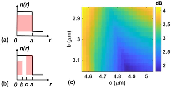
Figure 2.
Refractive index profile and Er-dopant distribution of (a) the Type-A and (b) Type-B 6-mode EDFs (the shaded region represents Er ion doping). (c) DMG of Type-B 6-mode EDFA as a function of b and c.

Table 1.
Fiber parameters of the two different types of EDFs.
3. Results and Discussion
To study the role of mode mixing in reducing the DMG in FM-EDFAs, we compared the DMG of a Type-A 6-mode EDFA with and without strong MC. Figure 3 shows MG as a function of EDF length at a pump power of 1 W, which is much higher than the signal power of 0.1 mW mentioned in Section 2. In an uncoupled case (Figure 3a), MG gradually increases until saturation point at ~12 m and the overall DMG of the amplifier is reached at ~9.3 dB. In a strong mode coupling regime (Figure 3b–d), however, a 6-mode EDFA can obtain a much lower DMG by increasing the degree of the MC, equivalent to increasing the CS or NCP. For example, as shown in Figure 3d, the DMG is reduced to 3.4 dB when NCP and CS are 600 and −10 dB/pt, respectively, which is 5.9 dB lower than that in Figure 3a.
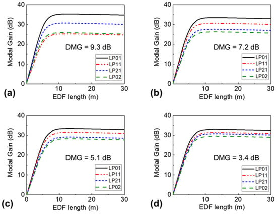
Figure 3.
MG as a function of EDF length in (a) uncoupled or strongly coupled 6-mode EDFAs; (b) NCP = 300, CS = −15 dB/pt; (c) NCP = 300, CS = −10 dB/pt; (d) NCP = 600, CS = −10 dB/pt.
Then, we focused on the effect of NCP and CS on DMG reduction in strongly coupled FM-EDFAs. Figure 4 shows the calculated DMD results of both Type-A and Type-B 6-mode EDFAs. NCP and CS are in the ranges 10 to 600 and −25 to −1 dB/pt, respectively. It should be noted that there are little variations in the calculated DMG values at fixed NCP and CS, resulting from the randomness of the coupling matrix and the location of each point. We calculated the DMG at each NCP and CS an average of 100 times. In the uncoupled case, the DMGs of Type-A and Type-B fiber amplifiers were 9.3 dB and 2.4 dB, respectively, but it was greatly improved by strong mode mixing. In particular, for the Type-A EDFA, an 8.2 dB DMG reduction (i.e., from 9.3 to 1.1 dB) was achieved via strong mode mixing, and the DMG of Type-B EDFA was reduced to 0.5 dB with the aid of optimized Er-dopant distribution. Therefore, we can say that the proposed approach is very powerful for high DMG amplifiers, but it is also very useful to further reduce it in moderate-DMG amplifiers.
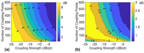
Figure 4.
DMG of (a) Type-A and (b) Type-B 6-mode EDFAs as a function of NCP and CS.
As mentioned before, NCP and CS are the key factors in reducing DMG. Considering the randomness of the coupling matrix and the location of each point, we then evaluated the DMG fluctuation of strongly coupled FM-EDFAs after 100 repeated calculations. We noticed that the DMGs of the two types of FM-EDFAs follow a similar trend as a function of NCP and CS (see Figure 4) and we chose a Type-A fiber amplifier (i.e., uniform doping), which is the most common and easiest to manufacture, for the following analysis. Figure 5 shows DMG and its corresponding standard deviation as a function of NCP and CS. As shown in Figure 5a, the DMG gradually decreases with CS and we can achieve a 7.8 dB reduction from 9.3 ± 0.3 to 1.5 ± 0.3 dB when NCP equals 300, as well as an 8.2 dB reduction when NCP equals 600. The DMG also decreases with NCP in Figure 5b from 8.6 ± 0.3 to 4.4 ± 0.7 dB when CS = −15 dB/pt and from 8.4 ± 0.5 to 2.7 ± 0.4 dB when CS = −10 dB/pt. It is worth noting that the standard deviation of DMG increased at the beginning due to the small number of NCP but decreased with NCP.
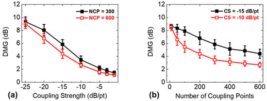
Figure 5.
DMG and corresponding standard deviation as a function of (a) CS at NCP = 300 and 600; (b) NCP at CS = −15 dB/pt and −10 dB/pt.
The average MGs and DMGs of (un)coupled FM-EDFAs were studied at different pump powers. As shown in Figure 6a, the average MGs in both cases are almost the same and the DMGs remained unchanged for pump power in the range of 200–1000 mW. Apart from low DMG, it was also important to obtain wideband operation and low noise figures (NF) for FM-EDFAs. Figure 6b shows the average MGs and DMGs over the full C-band. In both cases, the average MG spectra of the amplifiers was flat over the whole C-band and the wavelength dependence of the DMGs was also negligible. Thus, the gain bandwidth and flatness of the amplifier was not sacrificed via strong mode mixing in FM-EDFAs.
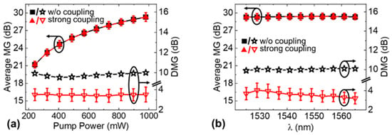
Figure 6.
(a) Pump power and (b) wavelength dependence of uncoupled and strongly coupled 6-mode EDFAs at NCP = 300 and CS = −10 dB/pt.
NF in FM-EDFAs can be written by [24], where gi and PASE_i represent the i-th MG and ASE noise power, respectively. Note that the difference of gi in the strongly coupled FM−EDFA is greatly reduced compared to an uncoupled fiber amplifier and strong mode mixing, making the ASE noise power consistent in different modes. Thus, NF in strongly coupled FM-EDFAs would be lower (or similar at least) than that of uncoupled amplifiers and the NF difference between spatial modes could be smaller.
4. Implementation of Strongly Coupled FM-EDFAs
The feasibility of our proposed strongly coupled FM-EDFAs was also examined. Various fiber-type mode scramblers can be considered as a strong MC, but we particularly focused on the long-period gratings (LPGs) inscription technique during the fiber drawing process by CO2 laser annealing [25,26] because it can provide highly controllable MC along the entire length of active fiber. According to [27], the grating angle Ψ0 and grating strength Δng are the most essential parameters for LPG inscription and directly determine CS. With Ψ0 = 0, the refractive index change is described as , where Λ is the grating period, ρ represents the asymmetric shape of the transverse index profile, and a is the core radius. Specifically, taking into consideration the dimension of our fibers, a 10% power transfer (i.e., CS = −10 dB) occurred after a 4 cm-long fiber when Δng equaled 7.5 × 10⁻⁵. For the abovementioned 6M-EDFAs, we chose the length of EDF to be 12 m, which can accommodate three hundred 4 cm-long LPGs in total, meaning NCP = 300. Moreover, according to [28], the mode-dependent loss (MDL) for the device is assumed to be 4 dB and uniformly distributed along the EDF. Table 2 summarizes the gain characteristics with or without losses for two types of EDFs. Although the averaged MGs was reduced by about 1 dB due to the MDL, there was little change in both DMGs and their standard deviations (only 0.5-dB and 0.2-dB changes of DMGs for Type-A and Type-B EDFs, respectively).

Table 2.
EDF gain characteristics w or w/o losses at CS = −10 dB/pt and NCP = 300.
Note that conventional LPGs are strongly wavelength-dependent, which may limit the gain bandwidth of the proposed amplifiers. The mode coupling induced by LPGs varies with the wavelength, which will also cause the DMG to vary with the wavelength based on the analysis in Section 3. Therefore, in order to obtain a low DMG over a wide band, wideband LPGs are needed. Many research works have recently reported that they can improve the bandwidth [29,30] using chirped grating profiles [31] or cascading several gratings with different periods [32], and the widest bandwidth achieved so far with an LPFG is ~300 nm (10-dB bandwidth) [33]. Therefore, we believe that the proposed strongly coupled FM-EDFAs can be achievable with currently available LPG fabrication techniques.
5. Conclusions
We have proposed a new strongly coupled FM-EDFA design to realize low DMG and developed the amplifier model for the first time. Using this approach, significant DMG reductions could be obtained for both uniformly doped and dual-layer 6-mode EDFAs, and a wideband operation was confirmed across the C-band. We believe that the proposed strongly coupled FM-EDFAs can be further scaled to a large number of spatial modes and are achievable using currently available long-period fiber fabrication technologies.
Author Contributions
Y.L. planned and wrote the paper. X.W. contributed to the writing of the fourth part. Z.Y. took the overall responsibility in managing the manuscript. Y.J. revised the whole article and gave some advice. L.Z. supervised the work and provided technical leadership. All co-authors contributed to the final version with suggestions and critical comments. All authors have read and agreed to the published version of the manuscript.
Funding
National Key R&D Program of China under grant 2019YFB2203902 and National Natural Science Foundation of China under Grant 61775165.
Institutional Review Board Statement
Not applicable.
Informed Consent Statement
Not applicable.
Data Availability Statement
Not applicable.
Acknowledgments
The authors would like to thank the anonymous reviewers for their valuable comments and suggestions to improve this manuscript.
Conflicts of Interest
The authors declare no conflict of interest.
References
- Richardson, D.; Fini, J.M.; Nelson, L.E. Space-division multiplexing in optical fibres. Nat. Photon. 2013, 7, 354–362. [Google Scholar] [CrossRef] [Green Version]
- Li, G.; Bai, N.; Zhao, N.; Xia, C. Space-division multiplexing: The next frontier in optical communication. Adv. Opt. Photon. 2014, 6, 413–487. [Google Scholar] [CrossRef] [Green Version]
- Mizuno, T.; Takara, H.; Shibahara, K.; Sano, A.; Miyamoto, Y. Dense Space Division Multiplexed Transmission Over Multicore and Multimode Fiber for Long-haul Transport Systems. J. Light. Technol. 2016, 34, 1484–1493. [Google Scholar] [CrossRef]
- Bai, N.; Ip, E.; Wang, T.; Li, G. Multimode fiber amplifier with tunable modal gain using a reconfigurable multimode pump. Opt. Express 2011, 19, 16601–16611. [Google Scholar] [CrossRef] [Green Version]
- Krummrich, P.M. Optical Amplifiers for Multi Mode/Multi Core Transmission. In Proceedings of the Optical Fiber Communication Conference Postdeadline Papers, Los Angeles, CA, USA, 4–8 March 2012. [Google Scholar]
- Gaur, A.; Rastogi, V. DMG control in six-mode-group EDFA for Space Division Multiplexing. In Proceedings of the 13th International Conference on Fiber Optics and Photonics, Kanpur, India, 4–8 December 2016. [Google Scholar]
- Trinel, J.-B.; Le Cocq, G.; Andresen, E.R.; Quiquempois, Y.; Bigot, L. Latest results and future perspectives on Few-Mode Erbium Doped Fiber Amplifiers. Opt. Fiber Technol. 2017, 35, 56–63. [Google Scholar] [CrossRef]
- Jung, Y.; Kang, Q.; Sahu, J.K.; Corbett, B.; O’Callagham, J.; Poletti, F.; Alam, S.-U.; Richardson, D. Reconfigurable Modal Gain Control of a Few-Mode EDFA Supporting Six Spatial Modes. IEEE Photon. Technol. Lett. 2014, 26, 1100–1103. [Google Scholar] [CrossRef]
- Fontaine, N.K.; Huang, B.; Eznaveh, Z.S.; Chen, H.; Cang, J.; Ercan, B.; Velázquez-Benetez, A.; Chang, S.H.; Ryf, R.; Schulzgen, A.; et al. Multi-mode Optical Fiber Amplifier Supporting over 10 Spatial Modes. In Proceedings of the Optical Fiber Communications Conference (OFC), Anaheim, CA, USA, 20–22 March 2016. [Google Scholar]
- Zhang, Z.; Guo, C.; Cui, L.; Mo, Q.; Zhao, N.; Du, C.; Li, X.; Li, G. 21 spatial mode erbium-doped fiber amplifier for mode division multiplexing transmission. Opt. Lett. 2018, 43, 1550–1553. [Google Scholar] [CrossRef] [PubMed]
- Chen, H.; Fontaine, N.K.; Ryf, R.; Jin, C.; Huang, B.; Shang, K.; Essiambre, R.-J.; Wang, L.; Hayashi, T.; Nagashima, T.; et al. Demonstration of Cladding-Pumped Six-Core Erbium-Doped Fiber Amplifier. J. Light. Technol. 2016, 34, 1654–1660. [Google Scholar] [CrossRef]
- Wada, M.; Sakamoto, T.; Aozasa, S.; Yamamoto, T.; Nakajima, K. L-band randomly-coupled 12 core erbium doped fiber am-plifier. In Proceedings of the Optical Fiber Communications Conference (OFC), San Diego, CA, USA, 3–7 March 2019. [Google Scholar]
- Arık, S.Ö.; Ho, K.; Kahn, J.M. Delay spread reduction in mode-division multiplexing: Mode coupling versus delay compensation. J. Lightw. Technol. 2015, 33, 4504–4512. [Google Scholar] [CrossRef]
- Liu, H.; Wen, H.; Huang, B.; Correa, R.A.; Sillard, P.; Chen, H.; Li, Z.; Li, G. Reducing group delay spread using uniform long-period gratings. Sci. Rep. 2018, 8, 3882. [Google Scholar] [CrossRef] [Green Version]
- Sakamoto, T.; Mori, T.; Wada, M.; Yamamoto, T.; Yamamoto, F.; Nakajima, K. Strongly-coupled multi-core fiber and its optical characteristics for MIMO transmission systems. Opt. Fiber Technol. 2017, 35, 8–18. [Google Scholar] [CrossRef]
- Ryf, R.; Fontaine, N.K.; Guan, B.; Essiambre, R.-J.; Randel, S.; Gnauck, A.H.; Chandrasekhar, S.; Adamiecki, A.; Raybon, G.; Ercan, B.; et al. 1705-km transmission over coupled-core fibre supporting 6 spatial modes. In Proceedings of the Optical Fiber Communications Conference (OFC), San Francisco, CA, USA, 9–13 March 2014. [Google Scholar]
- Wada, M.; Sakamoto, T.; Yamamoto, T.; Aozasa, S.; Nakajima, K. Low mode dependent gain few-mode EDFA with fiber based mode scrambler. In Proceedings of the Optoelectronics and Communications Conference (OECC/PSC), Fukuoka, Japan, 7–11 July 2019. [Google Scholar]
- Randel, S.; Schmidt, C.; Ryf, R.; Essiambre, R.-J.; Winzer, P.J. MIMO-based signal processing for mode-multiplexed transmission. In Proceedings of the Photonics Society Summer Topical Meeting Series, Seattle, WA, USA, 9–11 July 2012. [Google Scholar]
- Mecozzi, A.; Shtaif, M. The statistics of polarization-dependent loss in optical communication systems. IEEE Photon. Technol. Lett. 2002, 14, 313–315. [Google Scholar] [CrossRef]
- Choutagunta, K.; Arik, S.O.; Ho, K.-P.; Kahn, J.M.; Nagaraj, K.K.C. Characterizing Mode-Dependent Loss and Gain in Multimode Components. J. Light. Technol. 2018, 36, 3815–3823. [Google Scholar] [CrossRef]
- Becker, P.M.; Olsson, A.A.; Simpson, J.R. Erbium-Doped Fiber Amplifiers: Fundamentals and Technology; Elsevier: London, UK, 1999. [Google Scholar]
- Laurent, B.; Guillaume, L.C.; Yves, Q. Few-mode erbium-doped fiber amplifiers: A review. J. Lightw. Technol. 2015, 33, 588–596. [Google Scholar]
- Ip, E. Gain Equalization for Few-Mode Fiber Amplifiers Beyond Two Propagating Mode Groups. IEEE Photon. Technol. Lett. 2012, 24, 1933–1936. [Google Scholar] [CrossRef]
- Becker, P.C.; Olsson, N.A.; Simpson, J.R. Erbium-Doped Fiber Amplifiers Fundamentals and Technology; Elsevier: London, UK, 1998. [Google Scholar]
- Hirose, T.; Saito, K.; Kojima, S.; Yao, B.; Ohsono, K.; Sato, S.; Takada, K.; Ikushima, A. Fabrication of long-period fibre grating by CO2 laser-annealing in fibre-drawing process. Electron. Lett. 2007, 43, 443–445. [Google Scholar] [CrossRef]
- Wang, X.; Yang, Z.; Yu, W.; Liu, Y.; Di, Z.; Li, G.; Zhang, L. DMD Reduction by Strong Mode Coupling in Few-mode Fibers Using Multi-laser Inscribed LPFGs. In Proceedings of the Conference on Lasers and Electro-Optics (CLEO), Washington, WA, USA, 10–15 May 2020. [Google Scholar]
- Fang, J.; Li, A.; Shieh, W. Low-DMD few-mode fiber with distributed long-period grating. Opt. Lett. 2015, 40, 3937–3940. [Google Scholar] [CrossRef]
- Zhao, Y.; Chen, H.; Fontaine, N.K.; Li, J.; Ryf, R.; Liu, Y. Broadband and low-loss mode scramblers using CO2-laser inscribed long-period gratings. Opt. Lett. 2018, 43, 2868–2871. [Google Scholar] [CrossRef] [PubMed]
- Wang, W.; Wu, J.; Chen, K.; Jin, W.; Chiang, K.S. Ultra-broadband mode converters based on length-apodized long-period waveguide gratings. Opt. Express 2017, 25, 14341–14350. [Google Scholar] [CrossRef]
- Qiang, L.; Zhengtian, G.; Guan, T. Few-mode tilted long period fiber grating mode filter based on dual-peak resonance near phase-matching turning point. Optik 2020, 212, 164656. [Google Scholar]
- Chen, H.-R.; Kuan, W.-H.; Lin, K.-H. Ultrabroadband tunable long-period fiber grating for stress sensing and optical filtering. In Proceedings of the IEEE SENSORS, Glasgow, UK, 29 October–1 November 2017. [Google Scholar]
- Pérez-Sánchez, G.G.G.; Soto-Jasso, M.A.; Hernández-Valdez, G.; Ocampo-Hidalgo, J.J.; Medina-Velázquez, D.Y. Design and manufacturing of cascaded LPFG with CNC CO2 laser machine. In Photonic Fiber and Crystal Devices: Advances in Materials and Innovations in Device Applications XIV; SPIE: Bellingham, WA, USA, 2020. [Google Scholar]
- Zhao, X.; Liu, Y.; Liu, Z.; Mou, C. All-fiber bandwidth tunable ultra-broadband mode converters based on long-period fiber gratings and helical long-period gratings. Opt. Express 2020, 28, 11990–12000. [Google Scholar] [CrossRef] [PubMed]
Publisher’s Note: MDPI stays neutral with regard to jurisdictional claims in published maps and institutional affiliations. |
© 2022 by the authors. Licensee MDPI, Basel, Switzerland. This article is an open access article distributed under the terms and conditions of the Creative Commons Attribution (CC BY) license (https://creativecommons.org/licenses/by/4.0/).