Article

Analysis on Influences of Squeeze Film Damper on Vibrations of Rotor System in Aeroengine

1
School of Mechanical Engineering and Automation, Northeastern University, Shenyang 110819, China
2
Key Laboratory of Vibration and Control of Aero-Propulsion System Ministry of Education, Northeastern University, Shenyang 110819, China
*
Author to whom correspondence should be addressed.
Appl. Sci. 2022, 12(2), 615; https://doi.org/10.3390/app12020615
Submission received: 12 December 2021 / Revised: 6 January 2022 / Accepted: 7 January 2022 / Published: 9 January 2022
(This article belongs to the Special Issue Advancing Reliability & Prognostics and Health Management)

Abstract

:
Squeeze film damper (SFD) is widely used in the vibration suppression of aeroengine rotor systems, but will cause complex motions of the rotor system under specific operating conditions. In this paper, a lumped-mass dynamic model of the high-pressure rotor system in an aeroengine is established, and the nonlinear stiffness and damping formula of SFD are introduced into the above model. The vibration responses of the rotor system under different rotating speeds and with different unbalances are investigated numerically, and the influence of SFD on the rotor system vibration and the change of suppression ability are compared and analyzed. The results show that in the case of high speed, together with a small unbalance, the rotor system will perform a complex vibration or a bistable vibration due to SFD. If the unbalance is properly increased under the same case of high speed, the vibration of the rotor becomes single-harmonic and the bistable vibration disappears. The research results can provide a helpful reference for analyzing complex vibration mechanisms of the rotor system with SFD and achieving an effective vibration suppression through unbalance regulation.

1. Introduction

Squeeze Film Damper (SFD) is frequently used for the vibration reduction of rotor systems in aeroengines. The principle of vibration reduction is that the bearing outer ring is installed in the bearing seat with a certain clearance, which is introduced to lubricating oil to form squeeze oil film. The vibration load caused by the rotor approaching or passing the critical speed or by the unbalanced force is transmitted from the rotor to the elastic support through the bearing. Under the transverse load of the rotor, the journal produces radial displacement and the vibration energy then is absorbed by the lubricating oil. The typical installation method of SFD in a bearing is shown in Figure 1.
The influence of SFD on rotor systems is very significant, and it is an important vibration reduction element of many rotating machinery, such as aeroengines. Long-term theoretical and experimental research has been carried out by people. In the early stage, SFD was linearly equivalent to 8 coefficients (4 damping coefficients and 4 stiffness coefficients) [1]. However, the oil film force of SFD has obvious nonlinearity, and the linearization equivalent has shortcomings, causing many vibration phenomena which cannot be explained reasonably. The mechanism of nonlinear stiffness and damping of SFD is relatively clear now.
Based on the assumption that the oil film is incompressible, the oil film distribution of SFD obtained by solving the Reynolds equation with a short bearing and a Sommerfeld oil film boundary condition is dependent on instantaneous displacement and velocity. In Refs. [2,3], the fluid-structure coupling dynamics of SFD is analyzed by the finite difference method. The direct stiffness and damping coefficients and the cross stiffness and damping coefficients of SFD are obtained, which have the characteristics of hard nonlinearity. Theoretical and experimental studies also show that the introduction of SFD can improve the dynamic stability of the rotor system in a large speed range and the ability to bear serious unbalanced forces; however, there are nonlinear dynamic behaviors such as subharmonic, super harmonic, and torus orbit [4].
The nonlinearity of SFD has a significant influence on the dynamics of rotor systems. Professor Allaire [5,6] pointed out that the nonlinear oil film force of SFD causes uncoordinated whirling of the rotor, and thought that the most obvious nonlinear behavior of the SFD-rotor system was a bistable phenomenon; that is, corresponding to the same speed ratio, the response will appear multivalue. Under certain conditions, the motion trajectory under large eccentricity may be unstable, and low-frequency precession and self-excitation vibration corresponding to higher critical speed and damping pressure may occur [7,8]. Bai [9] analyzed and simulated the SFD effect of sudden unbalanced excitation on a low-pressure rotor system with a large fan, revealing the way in which SFD affects the rotor passing through the unstable region. Zhang J H. [10] from Tianjin University established the dynamic model of the aeroengine rotor system considering the maneuver flight of the aircraft, in which the Coulomb friction force of the rotor rubbing and the SFD damping force based on the Reynolds equation was introduced, and the motion bifurcation diagram of the speed was obtained. The SFD played different roles in stability under different flight states and speeds. He F. studied the effects of fluid inertia, unbalanced force, unidirectional load, stiffness of damper-centering spring on nonlinear vibration of a flexible rotor system, and the effects of oil pressure and bubble film cavitation [11,12], in detail with harmonic balance method and prediction-correction algorithm. Many scholars also use the stability and bifurcation theory to comprehensively analyze the nonlinear dynamic, non-coordinated motion and periodic solution bifurcation and stability of the SFD rotor system [13]. Zhou and Luo [14] made a detailed theoretical study on the influence of SFD with a floating ring structure on the nonlinear dynamic characteristics of rotor systems. In recent years, a great deal of theoretical research has been carried out around the dynamics of the SFD-rotor system. Chen [15] established the motion equation of a rotor-SFD system by using π oil film model with fluid inertia, and obtained the bifurcation equation of the rotor-SFD system by the averaging method. Qin [16] established the nonlinear analytical equation of an SFD-rotor system, obtained the Floquet multiplier by numerical calculation, and studied the nonlinear response and bifurcation. In Refs. [17,18], the influence of SFD on the spectrum of nonlinear vibration response is discussed. The contribution degree of connection nonlinearity and contact effect to the bistable state is compared. Sang [19] studied the effect of SFD in aeroengines with rub impact and misalignment, and found that SFD effectively reduced the vibration and strain of elastic support at the turbine disk caused by rub impact, in particular the vibration of double frequency caused by misalignment. Chen [20] analyzed the SFD effect of base excitations on a rotor system, revealing the way in which SFD affects the rotor passing through the unstable region. Ma [21] studied the influence of SFD on the nonlinear dynamic of dual-rotor systems supported by a rolling bearing. Zhang [22] developed a new integral elastic ring squeeze film damper (IERSFD) and analyzed the vibration reduction principle. The overcritical vibration experiment of the rotor was carried out under the conditions of an IERSFD chamber filled with liquids with different viscosity damping. Zhang [23] focused on the ability of the elastic ring of ERSFD to effectively adjust the dynamic pressure of oil film and suppress the nonlinear vibration of the rotor system. The influence of ring thickness, oil film thickness, and oil viscosity on vibration were studied.
At present, most of the research on SFD-rotor systems focuses on the qualitative mechanistic analysis of nonlinear dynamics. There is a lack of research on the direct comparison of vibration behavior under different speed conditions and unbalance. Especially, the research on structural characteristics and dynamic characteristics of typical aero-engine rotor systems lacks pertinence. In this paper, the nonlinear stiffness and damping of SFD are introduced to establish the corresponding dynamic differential equation according to the typical structure and dynamics, particularity of the aeroengine rotor system. In order to reveal the bounded complex vibration and bistable vibration of the rotor system caused by SFD and the law of influence of unbalance on unstable vibration, the response of the rotor system under different unbalances and different rotational speeds were studied.

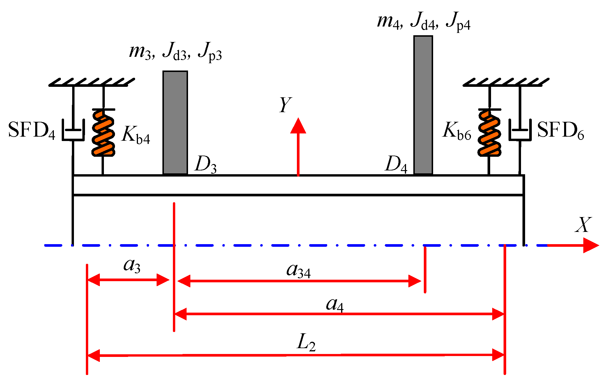
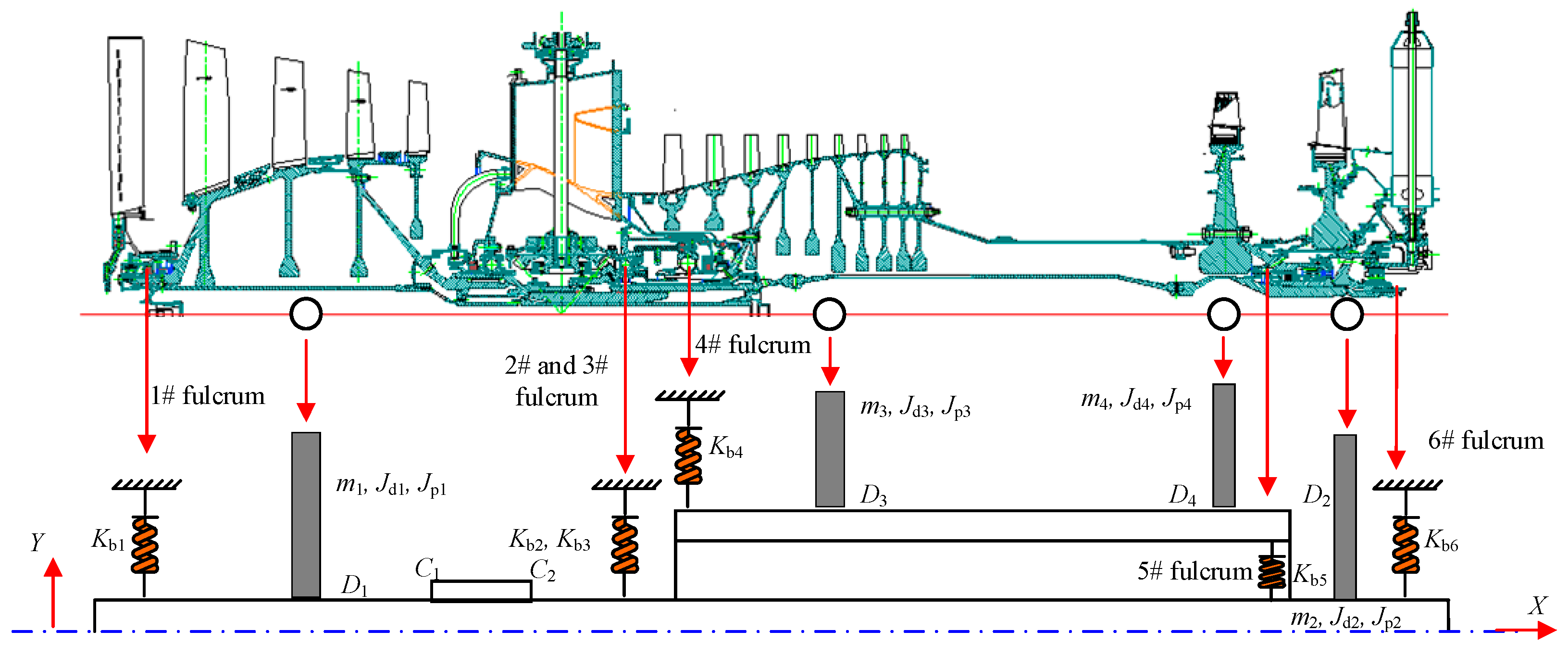
2. Dynamic Model of High-Pressure Rotor

The structure of an aeroengine is simplified, as shown in Figure 2. The engine consists of a high-pressure rotor system and a low-pressure rotor system. In engineering, the high-pressure rotor system shows unstable vibration or bistable vibration caused by SFD. This paper mainly takes the high-pressure rotor system as the research object.
The dynamic model of the high-pressure rotor system in Figure 2 is established. As shown in Figure 3, the front fulcrum of the high-pressure rotor is 4# fulcrum, which is composed of the equivalent stiffness of the elastic-supported combined structure and the nonlinear damping coefficient of the squeeze film damper at 4# fulcrum. The equivalent stiffness of the back fulcrum of the high-pressure rotor should be regarded as the series connection between the bearing stiffness of 5# fulcrum and the elastic support stiffness of 6# fulcrum. The series connection stiffness is approximately equal to the stiffness of 6# fulcrum; The damping coefficient of back fulcrum of the high-pressure rotor is provided by the squeeze film damper at 6# fulcrum.
The equivalent disk D3 of the high-pressure compressor has the vibration of y3 (vertical) and z3 (horizontal), and the rotation angles are θy3 and θz3, respectively. The vibrations corresponding to the equivalent disk D4 are y4 (vertical), z4 (horizontal), θy4, θx4. The differential equation of motion of the high-pressure rotor system is as follows:
( m 3 + m 4 ) y ¨ 3 + m 4 θ ¨ z 3 a 34 + q b 4 y y 3 + ( q b 3 y a 3 + q b 4 y a 4 ) θ z 3 + q b 3 y y 3 = 0
( m 3 + m 4 ) z ¨ 3 m 4 θ ¨ z 3 a 34 + ( q b 3 z a 3 q b 4 z a 4 ) θ z 3 + q b 3 z z 3 = 0
m 4 z ¨ 3 a 3 4 ( m 4 a 3 4 2 + J d 3 + J d 4 ) θ ¨ y 3 + Ω 3 ( J p 3 + J p 4 ) θ ˙ z 3 + ( q b 3 z a 3 2 + q b 4 z a 4 2 + q b 4 θ y ) θ y 3 + z 3 ( q b 3 z a 3 q b 4 z a 4 ) = 0
m 4 z ¨ 3 a 3 4 + ( m 4 a 3 4 2 + J d 3 + J d 4 ) θ ¨ z 3 Ω 3 ( J p 3 + J p 4 ) θ ˙ y 3 + ( q b 3 y a 3 2 + q b 4 y a 4 2 + q b 4 θ y ) θ z 3 y 3 ( q b 3 y a 3 q b 4 y a 4 ) = 0
where qb3y, qb4y, qb3y, qb4y represent the stiffness of the 4# fulcrum and 6# fulcrum in the y and z directions, and qb4θz represents the rotational stiffness of the 6# fulcrum in the z direction in Figure 3.
Considering the form of complex variables, and assume:
y = y 3 + i * z 3 ;   θ = θ z 3 i * θ y 3
Then the Equations (1)–(4) can be rewritten as:
( m 3 + m 4 ) y 3 + m 4 θ ¨ z 3 a 34 + q b 3 y + ( q b 3 z a 3 q b 4 z a 4 ) θ z 3 + q b 3 y y = 0
m 4 y ¨ 3 a 3 4 + ( m 4 a 3 4 2 + J d 3 + J d 4 ) θ ¨ Ω 3 ( J p 3 + J p 4 ) θ ˙ + ( q b 3 y a 3 2 + q b 4 y a 4 2 + q b 4 θ z ) θ y ( q b 3 y a 3 q b 4 y a 4 ) = 0
According to the dynamic differential equation of the high-pressure rotor and the stiffness assumption of the high-pressure rotor, the high-pressure rotor system has four degrees of freedom. There is inertia matrix M, gyro force matrix G, and stiffness matrix K, as follows:
(a) Inertia matrix M
[ m 3 + m 4 0 0 m 4 a 34 0 m 3 + m 4 0 0 0 m 4 a 34 m 4 a 3 4 2 + J d 3 + J d 4 0 m 4 a 34 0 0 m 4 a 3 4 2 + J d 3 + J d 4 ]
(b) Gyro force matrix G
[ 0 0 0 0 0 0 0 0 0 0 0 Ω 3 ( J p 3 + J p 4 ) 0 0 Ω 3 ( J p 3 + J p 4 ) 0 ]
(c) Stiffness matrix K
[ q b 3 y + q b 4 y 0 0 a 3 q b 3 y + a 4 q b 4 y 0 q b 3 z + q b 4 z a 3 q b 3 z a 4 q b 4 z 0 0 a 3 q b 3 z a 4 q b 4 z a 3 2 q b 3 z a 4 2 q b 4 z + q b 4 θ y 0 a 3 q b 3 y + a 4 q b 4 y 0 0 a 3 2 q b 3 y a 4 2 q b 4 y + q b 4 θ z ]

3. Numerical Result Analysis

3.1. Main Parameters

The mass parameters and stiffness parameters of the high-pressure rotor system are obtained by establishing a three-dimensional model of the high-pressure rotor system. The mechanical model parameters of the high-pressure rotor system include distance parameters, disk parameters, shaft size parameters, and fulcrum stiffness parameters. In this paper, the three-dimensional model and finite element calculation results are compared and analyzed, and then the parameters’ equivalent disk and the high-pressure rotor are obtained, as shown from Table 1, Table 2, Table 3 and Table 4.
Here, Td, Dd, dd, and Md represent the thickness, outer diameter, inner diameter, and mass of the disc, respectively.
Here, Dr, dr, and Mr represent the outer diameter, inner diameter, and mass of the rotor, respectively.

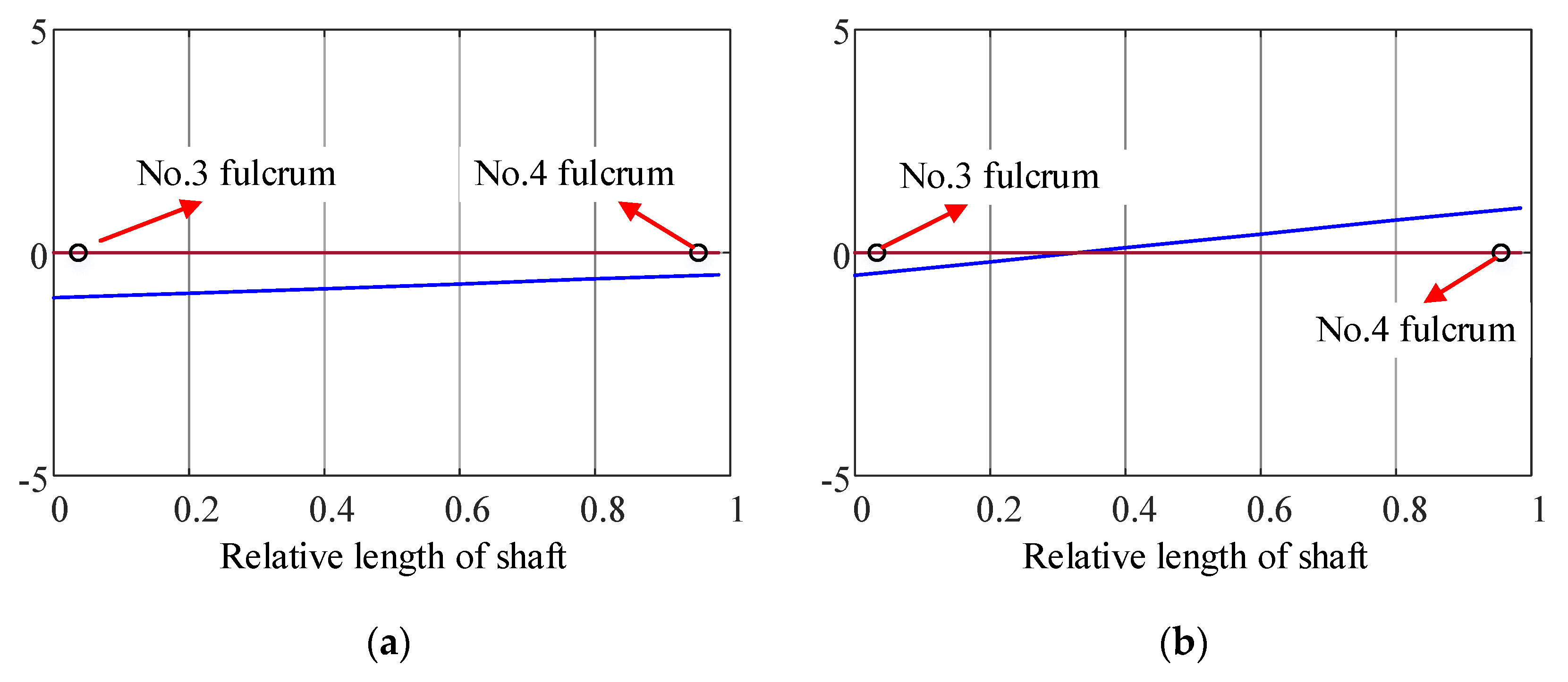
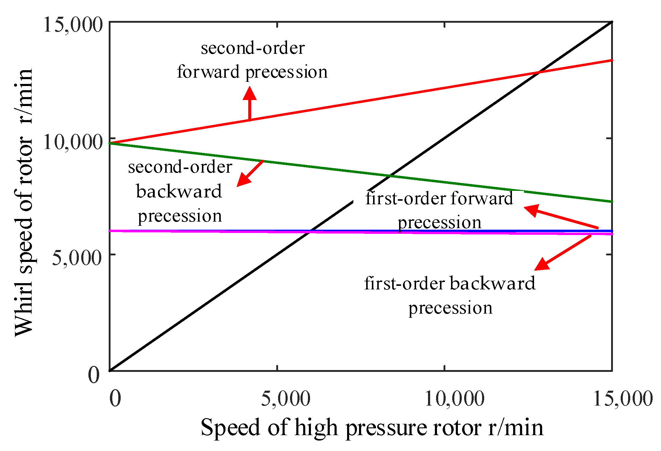
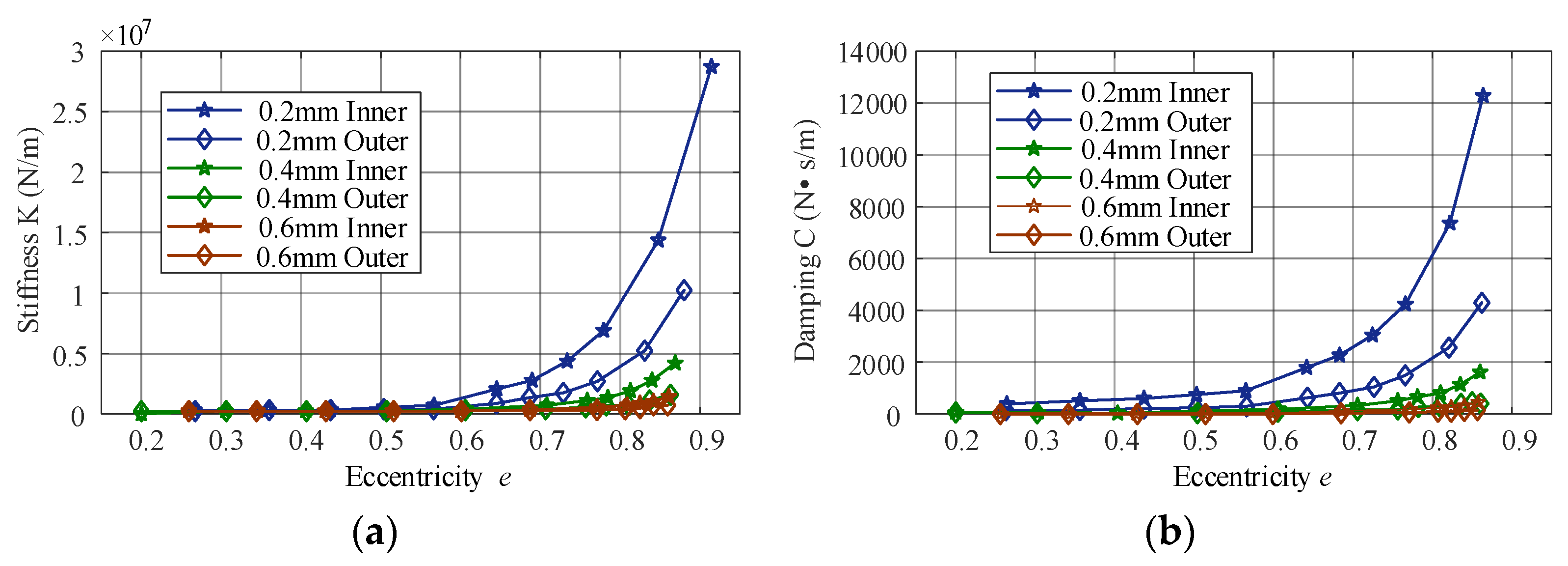
3.2. Dynamic Characteristic Analysis

According to the established lumped mass model of the high-pressure rotor system, the first two order rigid body modes (translation and pitch) and the dynamic characteristics about the first order bending mode are obtained. The natural frequency ωn of the rotor can be obtained by solving the characteristic roots of Equations (6) and (7). The natural circular frequency ωn of the rotor will change with the rotational angular velocity Ω. The critical angular velocity is the rotational angular velocity equal to the preceding angular velocity. Therefore, the critical angular velocity of the rotor can be calculated according to Ω = ωn. The calculated first two order modes of the high-pressure rotor system are shown in Figure 4.
Calculating the modal frequency at different speeds from 0 to 15,000 rpm, the Campbell diagram of the high-pressure rotor is obtained in Figure 5. The intersection point of the line with slope 1 and other curves is the critical speed of the high-pressure rotor in reverse precession and forward precession, respectively.
According to the Campbell diagram, the intersection of the straight line with slope 1 and forward precession and backward precession is the critical speed. The critical speed of the high-pressure rotor system is shown in Table 5.

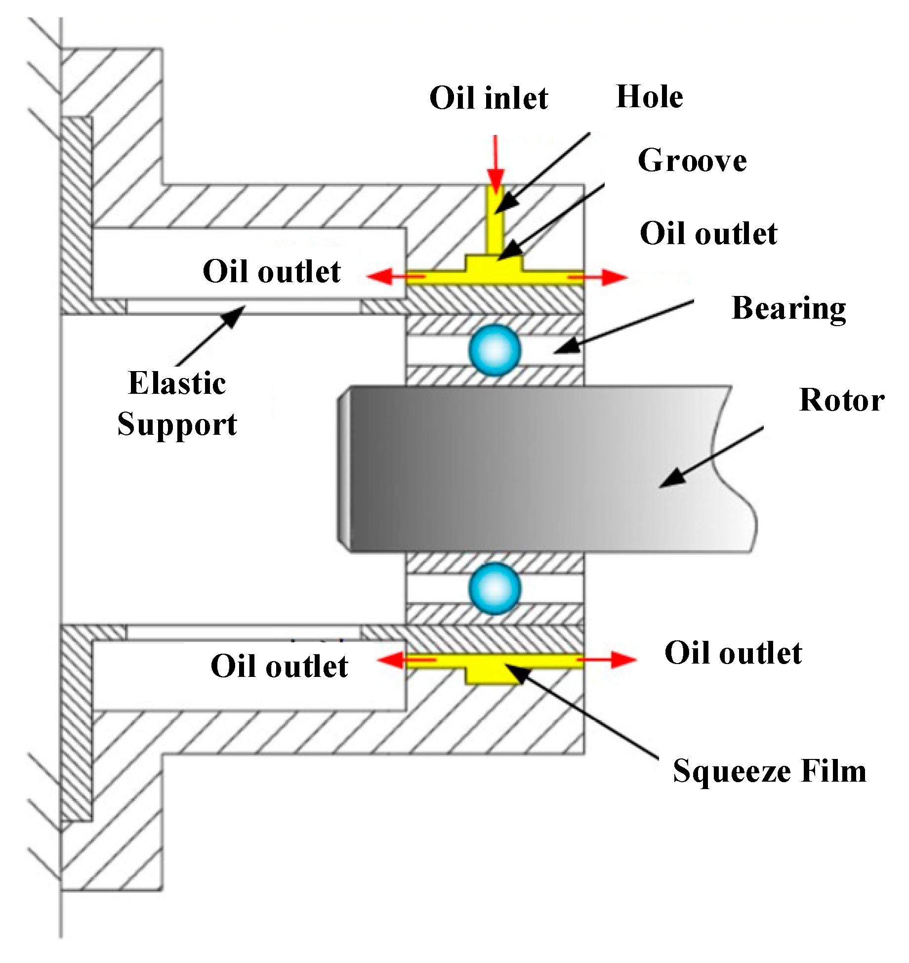
4. The Influence of SFD on the Vibration of the Rotor System

4.1. Calculation Method of Rotor Vibration Response

Damping is not considered in the determination of dynamic differential equation of the high-pressure rotor system. The damping and excitation force of the rotor system need to be introduced into the calculation of unbalanced vibration response. The governing equation of the rotor system can be written as:
M q ¨ + ( G + C ) q ˙ + K cg q = Q
where M, G, C, Kcg, and Q are mass matrix, gyro moment matrix, damping matrix, stiffness matrix, and unbalanced excitation vector, respectively.
When considering the unbalance excitation of the disk, the unbalance force vector in the y and z directions is:
{ F y = m e Ω 3 2 cos ( Ω 3 t + ϕ 3 ) F y = m e Ω 3 2 sin ( Ω 3 t + ϕ 3 )
The initial phase of the center of mass of the disk is ϕ3 (rad), the unbalanced mass is me (kg·m), the angular velocity of the rotor is Ω3 (rad/s), and the running time is t (s).
When calculating the dynamic response, Rayleigh damping is simple and convenient, and is widely used in structural dynamic analysis. The damping considers that the damping matrix of the structure is a linear combination of the mass matrix and the stiffness matrix, and has the following form:
C = α M + β K
where α and β are damping coefficients, which are related to the modal damping ratio ξ of the structure.
α = 2 ω 1 ω 2 ( ξ 1 ω 2 ξ 2 ω 1 ) / ( ω 2 2 ω 1 2 ) β = 2 ( ξ 2 ω 2 ξ 1 ω 1 ) / ( ω 2 2 ω 1 2 )
The numerical integration method can be used to solve the above equations. Newmark-β integration method is adopted in this paper, which belongs to one of the step-by-step integration methods [24,25]. According to the size of the time step, when the dynamic response in the next time step is analyzed, the results have good convergence.

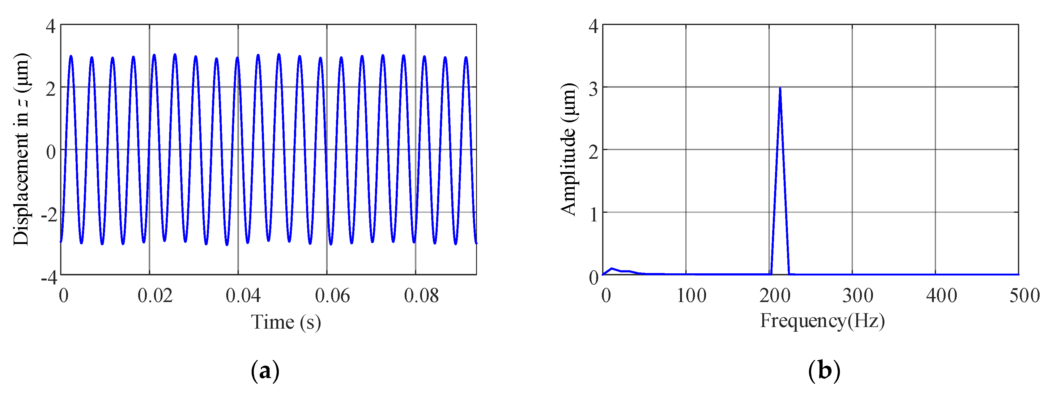
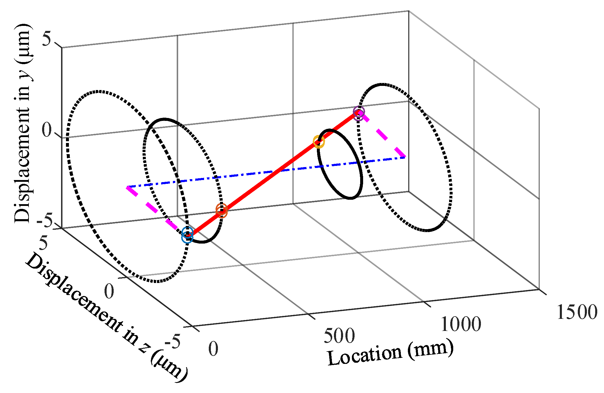
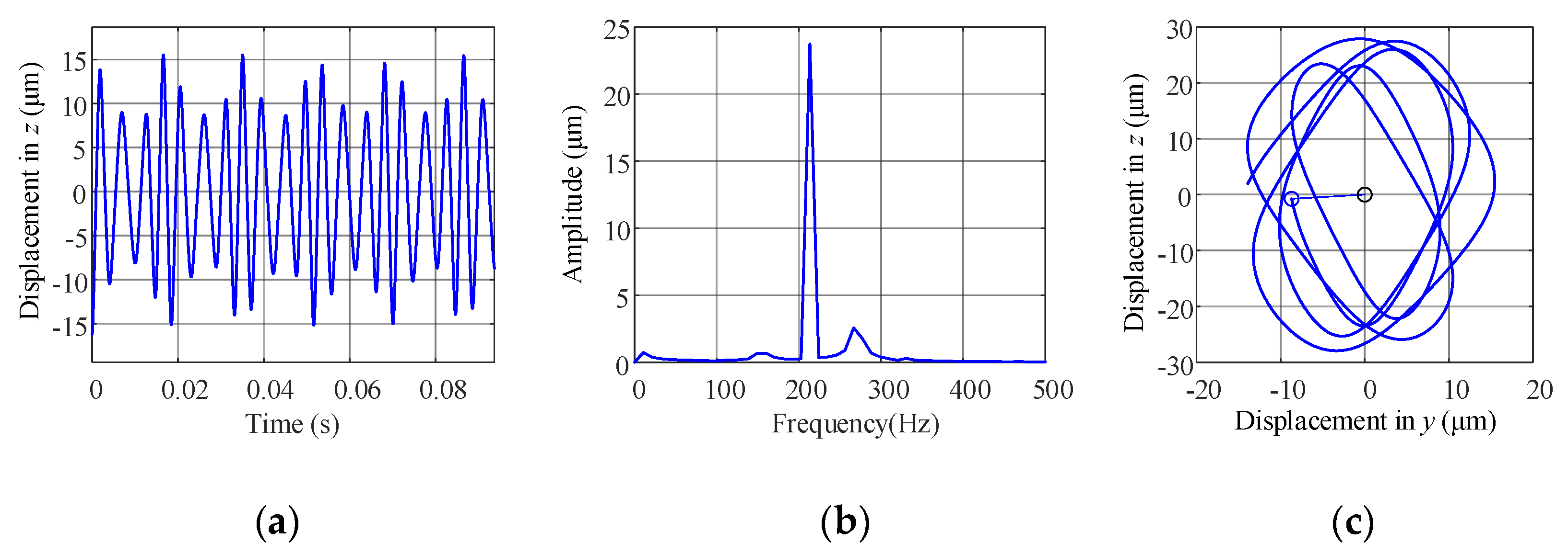
4.2. The Unbalanced Vibration Response of the Rotor without SFD

The sub-critical and over-critical of the rotor system, respectively, refer to the state when the speed is slightly lower and higher than the critical speed, which is of great significance for the analysis of the rotor’s dynamic stability. This paper first analyzes the unbalanced vibration response of the rotor system under sub-critical and over-critical conditions without SFD. The vibration response under low speed rn = 2000 r/min is shown in Figure 6. The vibration amplitude is about 2.1 μm, and the orbit is a complete circle, as shown in Figure 7.
In the case of high speed rn = 12,800 r/min, the vibration response is shown in Figure 8. The amplitude is about 3 μm, and the orbit is a complete circle, as shown in Figure 9. It can be found that the vibration response amplitude of the rotor system without SFD is very small (less than 5 μm) at different speeds, and the orbits are complete circles.

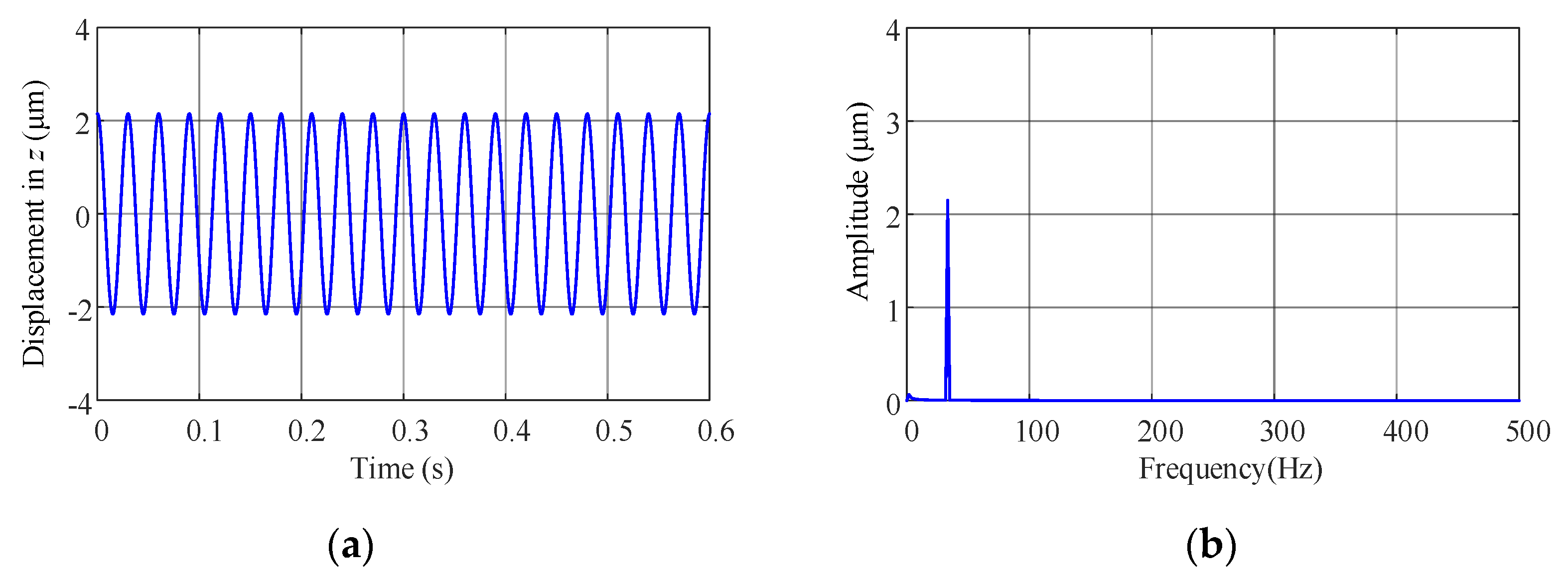
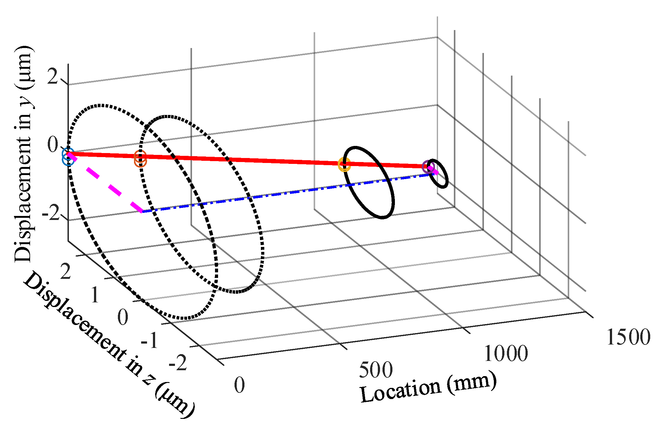
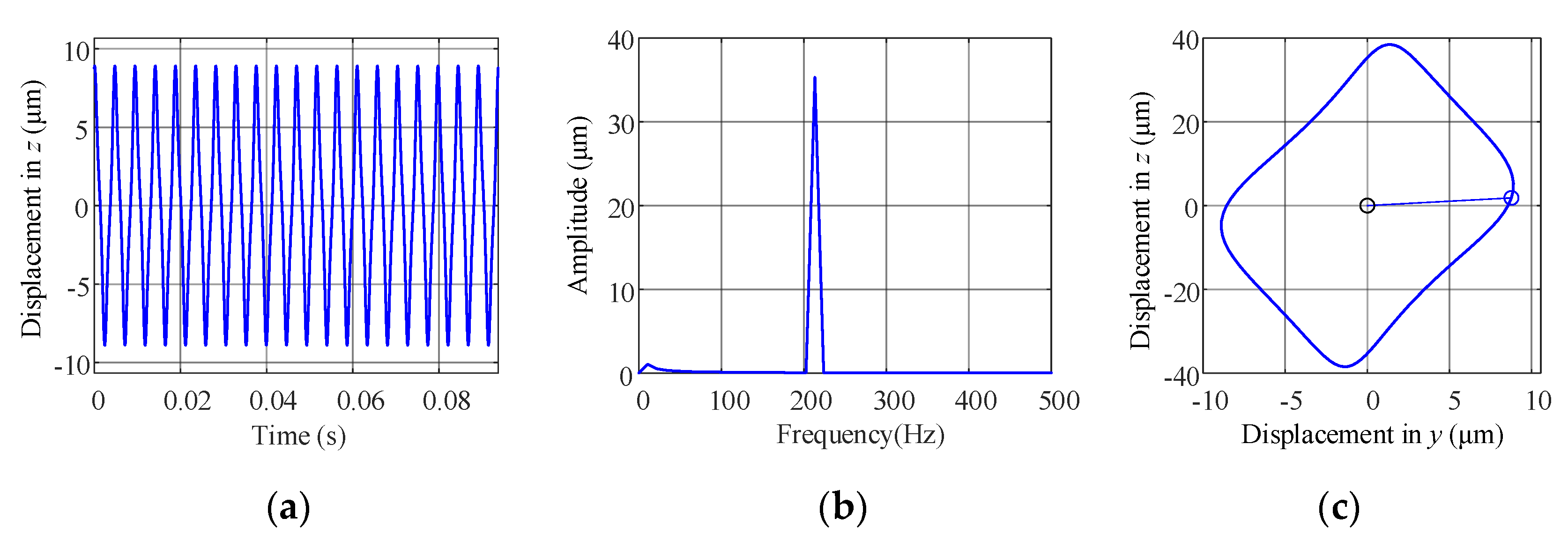
4.3. The Unbalanced Vibration Response of Rotor System with SFD

When the back fulcrum is set with SFD, it is known that the stiffness and damping of SFD have nonlinearity [3], and its typical stiffness and damping curves are shown in Figure 10.
Under the condition of high speed and large unbalanced mass, such as rn = 12,800 r/min, which is higher than the second-order critical speed, me = 4 × 10⁻⁴ kg·m, the calculated rotor vibration response is shown in Figure 11.
The unbalanced mass increases, namely me = 4 × 10⁻³ kg·m. Under the same high speed rn = 12,800 r/min, the vibration response of the rotor system is calculated, as shown in Figure 12.
When SFD is introduced into the back fulcrum, under the condition of high speed and large unbalance, the components in the time domain and frequency domain are complex, the orbit is complex, and the amplitude increases 4 times to about 24 μm. When the unbalance is further increased, the orbit tends to be regular and approximately rectangular, with rounded corners, and the amplitude increases to about 40 μm.
By contrast, under the condition of high speed and small imbalance, the vibration is also stable. For example, when the unbalanced mass me = 4 × 10⁻⁵ kg·m and the speed rn = 12,800 r/min, the vibration response is shown in Figure 13.
It can be seen from Figure 13 that under the conditions of high speed and small unbalance, the amplitude is only about 0.3 μm, the time domain and frequency domain components are simple, the vibration is stable, and the orbit is a regular circle. By introducing SFD, in the high speed, after increasing the unbalance, the rotor vibration becomes more stable, which improves the stability of the rotor. After reducing the unbalance, the vibration response amplitude can be significantly decreased.
Through qualitative comparative analysis with the relevant experiment results of the SFD-rotor system in Refs. [14,26], the stability of the SFD-rotor system can be improved by appropriately increasing the unbalance. This is essentially consistent with the simulation results in this paper, which verifies the correctness of the simulation model and analysis results. In subsequent research, we will use the to-be-built test rig to further carry out the experiments about vibration and stability of the SFD-rotor system.

5. Conclusions

In this paper, the high-pressure rotor system of an aeroengine is taken as the object. By taking the stiffness and damping of squeeze film damper, the dynamic model of the high-pressure rotor system is established. By comparing the unbalanced vibration responses before and after the introduction of SFD into the high-pressure rotor system, the following conclusions can be drawn:
(1) After introducing SFD into the rotor system, when the unbalance of the rotor increases from 4 × 10⁻⁴ kg·m to 4 × 10⁻³ kg·m or decreases from 4 × 10⁻⁴ kg·m to 4 × 10⁻⁵ kg·m, the orbits all change from unstable to stable, indicating that the unbalance has a great influence on the stability of the rotor. The appropriate unbalance can effectively improve the stability of the rotor.
(2) The rotor vibration response will appear as a bistable or unstable vibration at high speed and small unbalance. If the unbalance is properly increased, the vibration amplitude becomes larger, but the vibration response becomes a single-frequency stable vibration. The numerical simulation results also show that high and low rotational speeds and different unbalances lead to different steady-state characteristics.
(3) The unbalanced vibration of the rotor system with squeeze film damper is special. The bounded complex vibration will appear in the case of high rotational speed and small unbalanced mass. By increasing the unbalanced mass, the unstable vibration can be converted into stable state, and the stability of rotor vibration can be improved.
Through this dynamic model, the steady-state characteristics and sudden unbalance response characteristics of rotor system can be studied and analyzed quickly and accurately. Although the current unbalanced mass control is relatively strict, we need to know the influence of unbalanced mass on the vibration characteristics of the rotor system. Using the analysis method in this paper, in the design stage of the rotor system, engineers can analyze the influence of the allowable value of unbalance on the vibration and stability of the rotor, and provide a reference for the final design parameters. This article only puts forward the influence of the unbalanced mass value on rotor vibration, and provides a theoretical reference for engineering practice.

Author Contributions

Conceptualization, Q.H., Y.Z. and H.W.; data curation, Y.Z.; formal analysis, H.W.; funding acquisition, Q.H.; investigation, H.W.; methodology, Y.Z. and H.W.; project administration, Q.H.; resources, Q.H. and Z.L.; software, Y.Z.; supervision, H.W. and Y.Z.; validation, Y.Z.; visualization, H.W.; writing—original draft, H.W.; writing—review and editing, Y.Z. All authors have read and agreed to the published version of the manuscript.

Funding

This research received no external funding.

Acknowledgments

This work was financially supported by the National Natural Science Foundation of China [grant No. 12072069].

Conflicts of Interest

The authors declare that they have no conflict of interest.

References

  1. Cao, J.; Dimond, T.; Allaire, P. Numerical analysis of flexible rotor with nonlinear bearings and squeeze film dampers. In ASME International Mechanical Engineering Congress and Exposition; American Society of Mechanical Engineers: New York, NY, USA, 2014; Volume 46483, p. V04BT04A071. [Google Scholar]
  2. Zhang, W.; Ding, Q. Elastic ring deformation and pedestal contact status analysis of elastic ring squeeze film damper. J. Sound Vib. 2015, 346, 314–327. [Google Scholar] [CrossRef]
  3. Wang, X.; Han, Z.; Ding, Q.; Zhang, W. Influence of fluid inertia on dynamic characteristics of elastic ring squeeze film damper-rotor system. Hangkong Dongli Xuebao/J. Aerosp. Power 2018, 33, 2981–2990. [Google Scholar]
  4. He, F.; Allaire, P.E.; Dousti, S.; Untaroiu, A. Forced response of a flexible rotor with squeeze film damper under parametric change. In Turbo Expo: Power for Land, Sea, and Air; American Society of Mechanical Engineers: New York, NY, USA, 2013; Volume 55263, p. V07AT29A026. [Google Scholar]
  5. Gunter, E.J.; Barrett, L.E.; Allaire, P.E. Design of nonlinear squeeze-film dampers for aircraft engines. J. Lubr. Technol. 1977, 99, 57–64. [Google Scholar] [CrossRef]
  6. Allaire, P.E.; Barrett, L.E.; Gunter, E. Variational method for finite length squeeze film damper dynamics with applications. Wear 1977, 42, 9–22. [Google Scholar] [CrossRef]
  7. Hibner, D.H.; Kirk, R.G.; Buono, D.F. Analytical and experimental investigation of the stability of inter shaft squeeze film dampers—Part 1: Demonstration of instability. ASME J. Eng. Gas Turbines Power Ser. A 1972, 99, 47–52. [Google Scholar] [CrossRef]
  8. Kirk, R.G.; Hibner, D.H. A note on blade loss dynamics of rotor-bearing systems. J. Eng. Ind. 1976, 96, 497–503. [Google Scholar] [CrossRef]
  9. Bai, J.; Pan, B. Sudden unbalance response analysis of cantilever rotor system with squeeze film damper. Sci. Technol. Eng. 2018, 18, 299–305. [Google Scholar]
  10. Zhang, J.H.; Liang, M.A.; Xin, L.U.; Wang, J.; Lin, J. Effect of squeeze film damper on rotor system with rub-impact fault under maneuvering flight conditions. J. Xi’an Jiaotong Univ. 2015, 49, 62–70. [Google Scholar]
  11. Younan, A.A.; Cao, J.; Dimond, T.W.; Allaire, P.E. Nonlinear analysis of squeeze film damper with entrained air in rotor dynamic systems. Tribol. Trans. 2010, 54, 132–144. [Google Scholar] [CrossRef]
  12. He, F.; Allaire, P.; Dimond, T. Use of the harmonic balance method for flexible aircraft engine rotors with nonlinear squeeze film dampers. In Proceedings of the ASME 2014 International Design Engineering Technical Conferences and Computers and Information in Engineering Conference (DETC2014-35364, V008T11A071), Buffalo, NY, USA, 17–20 August 2014; American Society of Mechanical Engineers Digital Collection: New York, NY, USA, 2014. [Google Scholar]
  13. Inayat-Hussain, J.I.; Kanki, H.; Mureithi, N.W. Stability and bifurcation of a rigid rotor in cavitated squeeze-film dampers without centering springs. Tribol. Int. 2001, 34, 689–702. [Google Scholar] [CrossRef]
  14. Zhou, H.; Luo, G.; Chen, G.; Wang, F. Analysis of the nonlinear dynamic response of a rotor supported on ball bearings with floating-ring squeeze film dampers. Mech. Mach. Theory 2013, 59, 65–77. [Google Scholar] [CrossRef]
  15. Chen, H.; Chen, Y.; Hou, L.; Li, Z. Bifurcation analysis of rotor–squeeze film damper system with fluid inertia. Mech. Mach. Theory 2014, 81, 129–139. [Google Scholar] [CrossRef]
  16. Qin, W.; Zhang, J.; Ren, X. Response and bifurcation of rotor with squeeze film damper on elastic support. Chaos Solitons Fractals 2009, 39, 188–195. [Google Scholar] [CrossRef]
  17. Luo, Z.; Wang, J.; Tang, R.; Wang, D. Research on vibration performance of the nonlinear combined support-flexible rotor system. Nonlinear Dyn. 2019, 98, 113–128. [Google Scholar] [CrossRef]
  18. Hu, L.; Liu, Y.; Zhao, L.; Zhou, C. Nonlinear dynamic response of a rub-impact rod fastening rotor considering nonlinear contact characteristic. Arch. Appl. Mech. 2016, 86, 1869–1886. [Google Scholar] [CrossRef]
  19. Sang, X.; Liao, M.; Li, W. Experimental study on the damping performance of squeeze film damper in rotor with faults. J. Vib. Meas. Diagn. 2015, 35, 978–981. [Google Scholar]
  20. Chen, X.; Gan, X.; Ren, G. Nonlinear responses and bifurcations of a rotor-bearing system supported by squeeze-film damper with retainer spring subjected to base excitations. Nonlinear Dyn. 2020, 102, 2143–2177. [Google Scholar] [CrossRef]
  21. Ma, X.X.; Ma, H.; Qin, H.; Guo, X.; Zhao, C.; Yu, M. Nonlinear vibration response characteristics of a dual-rotor-bearing system with squeeze film damper. Chin. J. Aeronautics 2021, 34, 128–147. [Google Scholar] [CrossRef]
  22. Zhang, L.; Lidong, H.E.; Chen, Z.; Wan, F.; Ding, J. Structure design of an integral elastic ring squeeze film damper and experiments on the rotor passing through critical speed. J. Vib. Shock. 2019, 38, 72–78. [Google Scholar]
  23. Zhang, W.; Han, B.; Xiang, L.I.; Sun, J.; Ding, Q. Multi-objective optimization design of rotor-squeeze film damper system based on cell mapping method. J. Mech. Eng. 2019, 55, 68–70. [Google Scholar]
  24. Gao, P.; Hou, L.; Chen, Y.; Astronautics, S.O. Nonlinear vibration characteristics of a dual-rotor system with inter-shaft bearing. J. Vib. Shock. 2019, 38, 1–10. [Google Scholar]
  25. Li, L.; Luo, Z.; He, F.; Sun, K.; Yan, X. An improved partial similitude method for dynamic characteristic of rotor systems based on Levenberg–Marquardt method. Mech. Syst. Signal Process. 2022, 165, 108405. [Google Scholar] [CrossRef]
  26. Zhang, W.; Han, B.B.; Zhang, K.; Ding, Q. Dynamic analysis of a rotor system supported on squeeze film damper with air entrainment. Int. J. Bifurc. Chaos 2017, 27, 1750212. [Google Scholar] [CrossRef]
Figure 1. Structure schematic of a bearing with SFD.
Applsci 12 00615 g001
Figure 2. The diagram of the simplified dual-rotor model with four disks and five fulcrums.
Applsci 12 00615 g002
Figure 3. Equivalent dynamic model of the high-pressure rotor system.
Applsci 12 00615 g003
Figure 4. Mode of high-pressure rotor: (a) first order, (b) second order.
Applsci 12 00615 g004
Figure 5. Campbell diagram of high-pressure rotor.
Applsci 12 00615 g005
Figure 6. Response of high-pressure rotor at low speed. (a) time domain response; (b) frequency domain response.
Applsci 12 00615 g006
Figure 7. Orbits of high-pressure rotor at low speed.
Applsci 12 00615 g007
Figure 8. Response of high-pressure rotor at high speed. (a) time domain response; (b) frequency domain response.
Applsci 12 00615 g008
Figure 9. Orbit diagram of high-pressure rotor at high speed.
Applsci 12 00615 g009
Figure 10. Typical stiffness and damping curves: (a) stiffness (b) damping.
Applsci 12 00615 g010
Figure 11. Vibration response under speed of rn = 12,800 r/min and unbalanced mass of me = 4 × 10⁻⁴ kg·m. (a) time domain response; (b) frequency domain response; (c) displacement.
Applsci 12 00615 g011
Figure 12. Vibration response under speed of rn = 12,800 r/min and unbalanced mass of me = 4 × 10⁻³ kg·m. (a) time domain response; (b) frequency domain response; (c) displacement.
Applsci 12 00615 g012
Figure 13. Vibration response under speed of rn = 12,800 r/min and unbalanced mass of me = 4 × 10⁻⁵ kg·m. (a) time domain response; (b) frequency domain response; (c) displacement.
Applsci 12 00615 g013
Table 1. Structural parameters of high-pressure rotor system.
a3 (mm)a4 (mm)a34 (mm)L2 (mm)
2409606801200
Table 2. Parameters of two disks.
ParametersTd (mm)Dd (mm)dd (mm)Md (Kg)Rotational Inertia (Kg·m2)
HPC80600250143.9Jp = 7.14, Jd = 3.58
HPT40700250103.4Jp = 7.60, Jd = 3.88
Table 3. Equivalent structural parameters of rotor.
ParametersDr (mm)dr (mm)Lr (mm)Mr (Kg)
Values25023012000
Table 4. Stiffness of front fulcrum and back fulcrum of the high-pressure rotor system.
FulcrumStiffness (N/m)
4#qb3y = 5 × 10⁷ qb3z = 1 × 10⁷
5#, 6#qb4y = 5 × 10⁷ qb4z = 3 × 10⁷ qb4θz = 0
Table 5. Critical speed of the high-pressure rotor system.
Direction of PrecessionFirst-Order Critical Speed/rpmSecond-Order Critical Speed/rpm
Forward601112,771
Backward59698241
Publisher’s Note: MDPI stays neutral with regard to jurisdictional claims in published maps and institutional affiliations.

