Abstract
Numerical homogenization is an excellent tool for the quick simplification of complex structures with a model that is much simpler and, at the same time, accurately reflects the mechanical behavior of the original model. Corrugated cardboard modeling, with all geometrical nuances preserved, is a complicated and time-consuming process. The transfer of a full 3D model of corrugated board composed of two flat layers and a corrugated middle layer to one layer only, with substitute elastic parameters, greatly simplifies this process. Because the individual layers of corrugated cardboard are made of paper with a grammage in the range of 80–200 g/m2, i.e., very thin plates, they are slightly buckled even in the initial configuration. These imperfections affect the equivalent parameters that are obtained in the homogenization process. This paper presents an approach of taking into account these imperfections when creating a simplified model. The numerical homogenization method based on the equivalence of elastic energy between a representative volumetric element (i.e., a part of a full 3D model) and an equivalent plate were applied. Different shapes of imperfections were analyzed in order to account for the buckling modes, notably for a specific unit deformation and curvature. Finally, one form of initial imperfections was proposed, which most accurately reflects the decrease in all plate stiffnesses.
1. Introduction
In recent years, there has been observed a constant growth in the popularity of corrugated board, which is widely used in the packaging industry. This was due to the great demand for packaging materials in the food, pharmaceutical and cosmetic industries. The COVID-19 global pandemic has contributed to the rapid growth of e-commerce, driven by a significant increase in individual shipments and home orders.
Nowadays, a strong argument in favor of the use of corrugated board is its eco-friendliness. Cardboard packaging is very easy to recycle or dispose of. Packaging can be made with any color prints, which is an attractive option for e-commerce companies as they can freely shape the appearance of the packaging.
The most important aspect of packaging is the appropriate protection of the goods during storage or transport. In order to correctly determine the load capacity of the packaging, a number of factors should be taken into account, such as the influence of humidity, the arrangement of perforations and holes, the type of the load or the location of the flaps. Manufacturers of cardboard packaging are searching for solutions that are economical and effective, which is why research on the durability and optimal design of corrugated cardboard products is constantly carried out [1,2]. Various tests are performed to assess the load capacity of boxes, including compressive, tensile and bending strength. The most common tests are the box compression test (BCT) and the edge crush test (ECT).
The load capacity of the packaging has been the subject of research conducted by many scientific groups for many years. As early as 1952, a formula for the strength of the packaging which takes into account the box perimeter, the overall ring crush strength and the box and corrugated layer constants was proposed [3]. Maltenfort presented the relationship between the critical force in BCT and the dimensions of the packaging based on the Concora liner test and empirical constants [4]. In 1963, McKee et al. proposed an approach that became one of the most popular methods of estimating the load capacity of packaging with a rectangular base [5]. The formula is based on the ECT value, box perimeter, bending stiffness of the walls and correction factors. The use of empirically determined correction factors reduces the versatility of the method because it is necessary to compute new values of these factors for each board quality and each packaging model.
In 1968, a formula for estimating the strength of the regular package was presented. As the McKee formula, it was based on the package perimeter, the ECT and plate bending stiffness, and, additionally, also took into account the buckling factor, stacking time and load ratio [6]. In 1985, Allerby et al. proposed other constants and exponents of the McKee formula [7], and in 1987, Schrampfer et al. modified the McKee formula for more cardboard cutting methods and equipment [8]. Kawanishi presented a formula for the load capacity of the packaging, which depends on several important factors, such as the grammage of the cardboard layers, cardboard thickness, take-up factor, average corrugation count, perimeter and type of the box, moisture of the walls and printed ratio [9]. In 1993, Batelka and Smith proposed an extension of the McKee formula to several other types of boxes, taking into account the width and depth of the package [10].
The finite element method (FEM) is often used for numerical analysis of packaging strength. Urbanik and Frank used FEM to compare the strength of the packaging with a formula based on, e.g., the Poisson’s ratio [11]. Nordstrand and Carlsson performed FEM simulations to compare the obtained effective cardboard transverse shear moduli with analytical predictions and experimental results [12,13]. Urbanik and Saliklis presented observations of buckling phenomena of corrugated cardboard boxes modeled with FEM [14]. In 2011, an overview of the analytical and numerical load capacity estimation of corrugated board packaging was presented by Sohrabpour and Hellström [15].
The layered structure of the cardboard and the anisotropy of the paper make numerical modeling difficult due to the necessity of knowing the material parameters of all corrugated board layers. The solution to this problem is a process called homogenization. Homogenization allows to reduce the complicated cross-section of the corrugated board to one layer, which significantly simplifies the numerical model and shortens the computation time. Using this method, the equivalent stiffnesses and the effective thickness of the model should be determined to ensure the same behavior before and after homogenization.
The analytical homogenization of corrugated board is based on the equations of the classical theory of material strength and the classical theory of laminates [16]. In numerical homogenization, the basic equations of the finite element method are also used. The authors in this work utilize the method proposed by Biancolini [17] and then extended by Garbowski and Gajewski [18], which is based on an energy balance between a representative volume element and an equivalent plate. Hohe presented a representative element of heterogeneous and homogenized elements, which is based on the strain energy [19]. By means of periodic homogenization, Buannic et al. obtained equivalent membrane and bending characteristics of the plates [20]. In 2010, Abbès and Guo determined the torsional stiffness of an orthotropic sandwich panel by splitting the panel into two beams [21]. In 2018, Ramírez-Torres et al. presented a multiscale asymptotic homogenization for a composite material with a layered hierarchical structure [22,23]. Gallo et al. proposed an approximation of the load capacity and deformation of a package while applying empirical observations [24]. The use of homogenization to analyze a thin-walled seating made of triple-wall corrugated cardboard is presented by Suarez et al. [25]. Garbowski et al. investigated the effect of creasing or perforation on the stiffness of corrugated board [26]. Mrówczyński et al. performed a sensitivity analysis in optimal design of single- and double-walled corrugated board packaging [1,2]. Nguyen-Minh et al. verified the accuracy and reliability of the homogenization methods in the static analysis of trapezoidally and sinusoidally corrugated panels [27].
The load capacity of the corrugated board depends on several factors. One of them is the imperfections of the cardboard layers resulting from the production process. In 1995, Nordstrand carried out parametric tests to investigate the sensitivity of the load capacity with the size of initial imperfections [28]. The influence of geometrical imperfections on the mechanical properties was presented by Lu et al. [29]. Nordstrand modified the nonlinear buckling analysis of Rhodes and Harvey orthotropic plates to account for initial cardboard imperfections [30]. Garbowski and Knitter-Piątkowska presented an analytical method of determining the bending stiffness of double-walled corrugated cardboard with imperfections [31].
In the present article, an approach to account for the geometric imperfections of corrugated cardboard in numerical homogenization of single-walled corrugated board is presented. The approach presented in this paper extends and generalizes the homogenization methods already presented in our previous works. This generalization concerns geometric imperfections built into the material. They are always present due to the very thin layers of paper used in the production of corrugated board and, therefore, cannot be ignored. The presented here method allows to easily take into account these geometric imperfections and thus correctly calculate the sought effective stiffnesses.
2. Materials and Methods
2.1. Material Parameters and Corrugated Cardboard Geometry
Corrugated cardboard is a fibrous material, and therefore it is highly orthotropic. The direction of the fibers in the individual cardboard layers determines the mechanical properties of the board components. For wood-based materials, two main directions can be distinguished: the machine direction (MD) and the cross direction (CD). The strength of paper and paperboard is more than twice as high in the MD than in the CD because the fibers are arranged along the MD in the production process (see Figure 1). In the cross direction, the material is more ductile, while in the machine direction, it is more resistant to tearing and crushing.
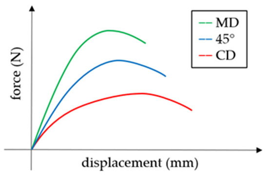
Figure 1.
The force-displacement curves in MD, CD and 45°.
The linear behavior of an elastic orthotropic material can be represented by the strain–stress relationship:
where and are the Young’s moduli in the MD and the CD, respectively; and are the Poisson’s coefficients; is the Kirchhoff’s modulus; and are the transverse shear moduli. The symmetry of the material stiffness/compliance matrix allows us to determine the relationship between the Poisson’s coefficients and the Young’s moduli:
The material orientation is always the same in all layers of corrugated cardboard. The machine direction coincides with the cardboard wave direction, which results from the technological conditions of the production process (see Figure 2). The lower strength in the cross direction is compensated by a take-up factor of the corrugated layer.
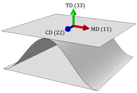
Figure 2.
Material orientation.
All corrugated board layers were modeled while using classical linear elastic orthotropy, see Equation (1). The material data were taken from the literature [17] and are presented in Table 1. The thickness of both flat layers (liners) and the corrugated layer (fluting) was assumed to be 0.30 mm.

Table 1.
Material data used in orthotropic constitutive model.
2.2. Homogenization Technique
The numerical homogenization method proposed by Biancolini [17], and then extended by Garbowski and Gajewski [18] was utilized in the present study. This method is based on the provision of strain energy equivalence between the full representative volume element (RVE) of the corrugated board and the simplified shell model. The RVE is a small, periodically repeating segment of the full corrugated board structure model that is then simplified to a single layer of flat shell elements in such a way as to ensure the same behavior of the full and simplified model. Only the most important assumptions of the described method are presented below. The entire theoretical derivation of the constitutive model can be found in [18]. However, it is important to note that for the evaluation of homogenized properties for macroscopic analysis, the concept of statistical RVE (SRVE) can be utilized [32,33,34].
The nodal displacements can be determined while involving the finite element method (FEM). The FEM equation for linear analysis is shown below:
where is a global stiffness matrix statically condensed to the external nodes of the RVE, is a displacement vector of the external nodes and is the vector of nodal forces applied to the external nodes. In Figure 3, the finite element mesh and nodes of the RVE are shown.
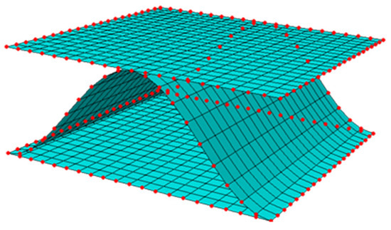
Figure 3.
Finite elements, external (in red color) and internal nodes of the corrugated cardboard.
The global stiffness matrix was obtained by applying the static condensation process. It consists in removing selected unknown degrees of freedom (DOF) and determining the stiffness matrix for a smaller number of DOFs (called primary unknowns). In the discussed model, the internal nodes were removed, and for the external nodes, the stiffness matrix was determined from the following formula:
where all the subarrays contain the stiffnesses for external (subscript ) and internal (subscript ) nodes, which in matrix form relate nodal displacements and nodal forces:
As a result of static condensation, the total elastic strain energy was reduced to the work of external forces on the corresponding displacements:
The balance of the total strain energy between the full 3D RVE model and the simplified shell model was ensured by appropriate determination of nodal displacements and by enabling the membrane and bending behavior. The details can be found in [18]. The relationship between generalized displacements and generalized strains can be presented by the formula:
where the matrix can be determined for each node (, , ):
Using the definition of elastic strain energy for a discrete model:
and analyzing a finite element model as subjected to basic types of loads (i.e., bending, tension and transverse shear), the elastic internal energy can be represented as:
The stiffness matrix for the homogenized composite can be determined from:
The matrix consists of the stiffness matrices:
where the subarray contains tensile and shear stiffnesses, the represents tension-bending coupling stiffnesses, the contains bending and torsional stiffnesses, and in the subarray the transverse shear stiffnesses are gathered.
In the case of symmetrical cross sections, the matrix is the zero matrix. For asymmetrical RVE, non-zero matrix elements appear in the matrix, which affects the matrix values. This problem can be solved by minimizing the matrix by choosing the position of the neutral axis, or, alternatively, the following formula can be used:
where the matrix contains coupled bending and torsional stiffnesses for the non-zero matrix.
2.3. Numerical Model with Imperfections
The main goal of this work was to implement geometric imperfections into the numerical model and to determine their influence on the stiffness reduction of corrugated board. Cardboard with a B flute (see Table 2) and material parameters contained in Table 1 were analyzed.
Table 2.
Geometric parameters of waves.
The application of imperfections in the numerical model of corrugated board consists in the appropriate definition of the buckling mode of the RVE. In the layers subjected to compression, the influence of imperfections is crucial. Therefore, due to the nature of the load, two cases should be considered: compression and bending. During compression, the entire cross section of the RVE is compressed, i.e., both the bottom and top liners. With regard to bending, one liner is compressed (assumed to be the bottom liner) and the other is tensioned. In the case of the liner, which is stretched, the imperfection does not affect the load capacity (in other words, it is not present); therefore, the tensile layers can be modeled as undeformed. During compression and bending, all or part of the middle cardboard layer is compressed. However, it was assumed that the influence of imperfections in this layer on stiffness is negligible due to the already existing corrugated shape of fluting.
The load direction of the corrugated board also affects the mode of buckling. During compression or bending in the machine direction, imperfections in the compressed layers are in the form of a half-sine wave across the entire depth of the RVE, where the support is the connection between liners and fluting (see Figure 4a,b). On the other hand, if the cardboard is loaded in the cross direction, then a half-wave appears in both directions, which causes dome-shaped imperfections. In this case, the support was provided by the external edges of the liners in the cross direction and the connection of the liners with fluting (see Figure 4c,d). Corrugated board may also contain imperfections that reflect in-plane shear and twisting of the RVE. For this reason, it was necessary to simulate these two load cases (see Figure 4e,f).
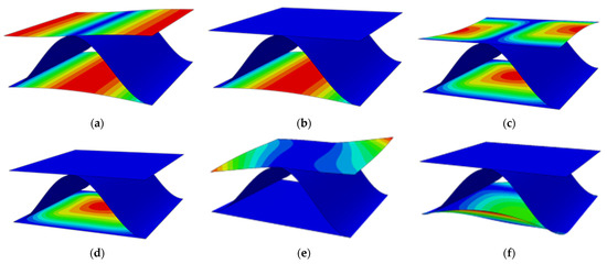
Figure 4.
Imperfection modes in the case of: (a) compression in the MD, (b) bending in the MD, (c) compression in the CD, (d) bending in the CD, (e) in-plane shear and (f) twisting.
Based on the above description, six modes of imperfection were analyzed, and thus six numerical models, which are presented in Figure 4. In each case, the amount of imperfections, i.e., the maximum deviation from the ideal shape (red color), was 5% of the cardboard height, which was 0.123 mm. For finite element method computation, the four-node quadrilaterals shell elements with reduced integration (S4R elements) were used. In all seven numerical models (one model without imperfections and six models with imperfections), the same mesh size was assumed. The approximate global size of the element was 0.1625 mm, which gave 4920 nodes, 4800 elements and 29,520 degrees of freedom.
3. Results
The corrugated cardboard model without initial imperfections and six models with six buckling modes were analyzed. Table 3 shows an example of the matrix computed for the RVE without imperfections (see Equation (12)).
Table 3.
Constitutive stiffness matrix for the cardboard model without imperfections.
Table 4 and Table 5 show the stiffness matrices for imperfection modes in the case of compression and bending in the machine direction. Table 6 and Table 7 present the RVE stiffness matrices with imperfections in the case of compression and bending in the cross direction. In Table 8 and Table 9, the constitutive stiffness matrices for imperfections in the case of in-plane shear and twisting are compiled.
Table 4.
Constitutive stiffness matrix for the cardboard model with imperfections in the case of compression in the MD.
Table 5.
Constitutive stiffness matrix for the cardboard model with imperfections in the case of bending in the MD.
Table 6.
Constitutive stiffness matrix for the cardboard model with imperfections in the case of compression in the CD.
Table 7.
Constitutive stiffness matrix for the cardboard model with imperfections in the case of bending in the CD.
Table 8.
Constitutive stiffness matrix for the cardboard model with imperfections in the case of in-plane shear.
Table 9.
Constitutive stiffness matrix for the cardboard model with imperfections in the case of twisting.
It should be noted that in the subarrays non-zero components are formed, which is caused by the asymmetry of the cross-section of the corrugated cardboard. Table 10 shows the stiffness values of the main diagonal matrices that are presented in Table 3, Table 4, Table 5, Table 6, Table 7, Table 8 and Table 9 for the model without imperfections (REF) and the six models with buckling modes (M1–M6). The imperfection modes were marked in the order presented in Figure 4, i.e., M1—compression in the MD, M2—bending in the MD, M3—compression in the CD, etc. Omitting the components does not introduce an error in the analysis of the results, because these components depend on the components , and on the Poisson’s ratio. The subarray was also disregarded, but its influence was taken into account by determining the uncoupled matrix from Equation (13). The components of the matrix were also omitted because their values remained almost unchanged for each buckling mode. Figure 5, Figure 6, Figure 7, Figure 8, Figure 9 and Figure 10 show the reduction of the individual stiffnesses for the analyzed six imperfection modes compared to the reference value that was computed from the model without imperfection. Table 11 presents the differences between the stiffnesses for models with imperfections and the stiffnesses of the reference model (without imperfections).
Table 10.
Selected stiffnesses for models without imperfections and with six imperfection modes.
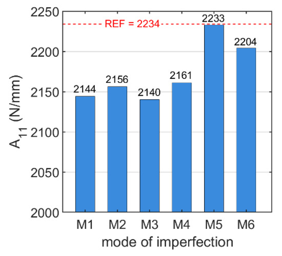
Figure 5.
stiffnesses for the six buckling modes (blue color) compared to the reference value (red color).
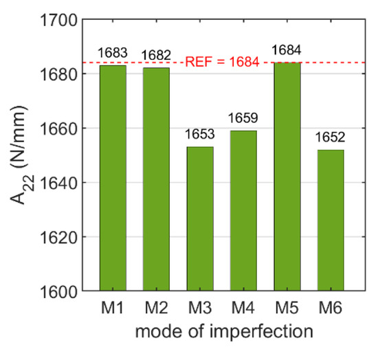
Figure 6.
stiffnesses for the six buckling modes (blue color) compared to the reference value (red color).
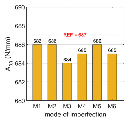
Figure 7.
stiffnesses for the six buckling modes (blue color) compared to the reference value (red color).
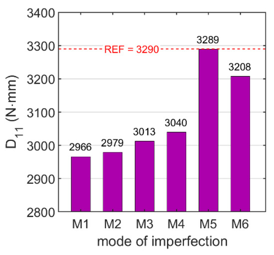
Figure 8.
stiffnesses for the six buckling modes (blue color) compared to the reference value (red color).
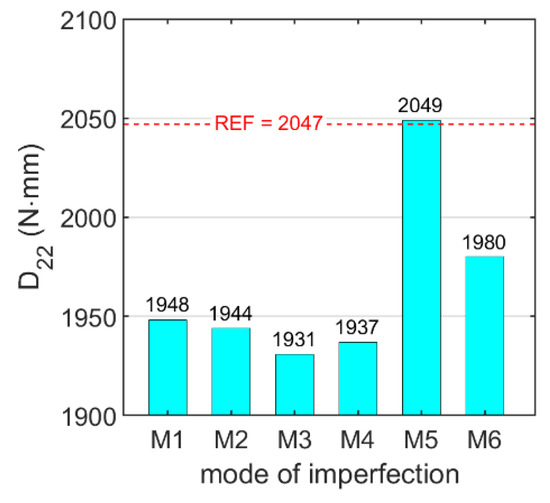
Figure 9.
stiffnesses for the six buckling modes (blue color) compared to the reference value (red color).
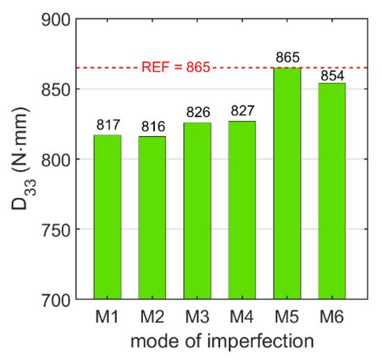
Figure 10.
stiffnesses for the six buckling modes (blue color) compared to the reference value (red color).
Table 11.
Stiffness degradation for models with imperfections (%).
4. Discussion
On the basis of the analyzed six buckling modes, reduced stiffness of the corrugated board was obtained due to the consideration of geometric imperfections (see Table 3, Table 4, Table 5, Table 6, Table 7, Table 8, Table 9 and Table 10). In Table 12, the final stiffnesses of the corrugated cardboard with imperfections are shown. The individual stiffness matrix components were selected from the corresponding imperfection modes as follows: —compression in the MD, —compression in the CD, —in-plane shear, —bending in the MD, —bending in the CD, —twisting.
Table 12.
Final stiffnesses of corrugated board with imperfections.
The data presented in Table 10 and Table 11 and Figure 5, Figure 6, Figure 7, Figure 8, Figure 9 and Figure 10 show that the stiffness did not change significantly for all analyzed buckling modes. The maximum decrease in the stiffness was 0.5%. The presented data, in particular the data summarized in Table 11, clearly show that taking into account the imperfection mode M5 causes negligible reduction of all stiffnesses. It can also be noticed that the greatest differences in stiffness (due to taking imperfections into account) occur for the stiffness , and a slightly smaller reduction occurs for the stiffness (see Table 12). The obtained values show that the bending stiffnesses are the most sensitive to disturbances in the ideal shape of the corrugated cardboard.
In order to save computational time, it was possible to analyze only one buckling mode instead of all six. Therefore, it was necessary to choose the buckling mode that gives the most similar results to those determined from the six imperfection cases. To determine this mode, the final stiffnesses from Table 12 were compared with the stiffness values for each buckling mode from Table 10. The smallest total error was obtained for the buckling mode M3, i.e., the compression in the CD, and it amounted to 5.3%. Slightly worse results were obtained for the modes M4—6.5%, M1 and M2—7.1%, and M6—12.9%. The worst fit was obtained for the in-plane shear case (mode M5). For this imperfection mode, the total error was as high as 23.5%. Based on the above results, it can be concluded that the most reliable results are obtained by analyzing the imperfections in the case of compression in the CD (see Figure 4c). This means that by using the imperfection geometry from the M5 model, it was possible to obtain drops in the values of the main stiffnesses, which correspond to the drops of the same stiffnesses but while using models with dedicated imperfections.
5. Conclusions
Nowadays, great emphasis is placed on the most optimal use of natural resources, including the production of corrugated cardboard. For this purpose, many research groups are trying to understand the behavior of cardboard depending on various factors in order to correctly model it. Taking the imperfections into account in the process of determining the equivalent stiffnesses is crucial because the geometrical deformations of the individual paper layers in the corrugated board are always present and cannot be ignored. The article presents an approach to taking into account such geometric imperfections in the modeling of corrugated board. The homogenization method, consisting in simplifying the full 3D model of the corrugated board to a single layer with equivalent parameters, was used. The numerical homogenization process was based on the elastic strain energy equivalence between the representative volume element and the equivalent plate. Taking into account geometric imperfections in the homogenization process is not obvious. The material may have initial imperfections of various shapes or imperfections, which are shaped by the loading conditions. Therefore, finding a universal geometry that reflects possible imperfections is very important for the correct determination of the effective parameters of a homogenized plate with a periodic core. On the basis of the conducted analyses, several conclusions were formulated regarding the influence of imperfections on the stiffness of the corrugated board, which enable a better understanding of the behavior of the corrugated board and thus more conscious design of the packaging structure made of this material.
Author Contributions
Conceptualization, D.M. and T.G.; methodology, D.M. and T.G.; software, T.G. and D.M.; validation, D.M., A.K.-P. and T.G.; formal analysis, D.M.; investigation, D.M. and A.K.-P.; resources, D.M.; data curation, D.M.; writing—original draft preparation, D.M.; writing—review and editing, A.K.-P. and T.G.; visualization, D.M.; supervision, T.G.; project administration, T.G.; funding acquisition, T.G. All authors have read and agreed to the published version of the manuscript.
Funding
This research received no external funding.
Institutional Review Board Statement
Not applicable.
Informed Consent Statement
Not applicable.
Data Availability Statement
The data presented in this study are available on request from the corresponding author.
Conflicts of Interest
The authors declare no conflict of interest.
References
- Mrówczyński, D.; Knitter-Piątkowska, A.; Garbowski, T. Non-Local Sensitivity Analysis and Numerical Homogenization in Optimal Design of Single-Wall Corrugated Board Packaging. Materials 2022, 15, 720. [Google Scholar] [CrossRef] [PubMed]
- Mrówczyński, D.; Knitter-Piątkowska, A.; Garbowski, T. Optimal Design of Double-Walled Corrugated Board Packaging. Materials 2022, 15, 2149. [Google Scholar] [CrossRef] [PubMed]
- Kellicutt, K.; Landt, E. Development of design data for corrugated fibreboard shipping containers. Tappi 1952, 35, 398–402. [Google Scholar]
- Maltenfort, G. Compression strength of corrugated containers. Fibre Contain 1956, 41, 106–121. [Google Scholar]
- McKee, R.C.; Gander, J.W.; Wachuta, J.R. Compression strength formula for corrugated boxes. Paperboard Packag. 1963, 48, 149–159. [Google Scholar]
- Whitsitt, W.J.; Gander, J.W.; McKee, R.C. Effect of Box Dimensions and Combined Board Creep Life on Box Creep Life; Institute of Paper Chemistry: Appleton, WI, USA, 1968. [Google Scholar]
- Allerby, I.M.; Laing, G.N.; Cardwell, R.D. Compressive strength—From components to corrugated containers. Appita Conf. Notes 1985, 1–11. [Google Scholar]
- Schrampfer, K.E.; Whitsitt, W.J.; Baum, G.A. Combined Board Edge Crush (ECT) Technology; Institute of Paper Chemistry: Appleton, WI, USA, 1987. [Google Scholar]
- Kawanishi, K. Estimation of the compression strength of corrugated fibreboard boxes and its application to box design using a personal computer. Packag. Technol. Sci. 1989, 2, 29–39. [Google Scholar] [CrossRef]
- Batelka, J.J.; Smith, C.N. Package Compression Model; Institute of Paper Science and Technology, Georgia Institute of Technology: Atlanta, GA, USA, 1993. [Google Scholar]
- Urbanik, T.J.; Frank, B. Box compression analysis of world-wide data spanning 46 years. Wood Fiber Sci. 2006, 38, 399–416. [Google Scholar]
- Nordstrand, T.; Carlsson, L. Evaluation of transverse shear stiffness of structural core sandwich plates. Compos. Struct. 1997, 37, 145–153. [Google Scholar] [CrossRef]
- Nordstrand, T. Basic Testing and Strength Design of Corrugated Board and Containers. Ph.D. Thesis, Lund University, Lund, Sweden, 2003. [Google Scholar]
- Urbanik, T.J.; Saliklis, E.P. Finite element corroboration of buckling phenomena observed in corrugated boxes. Wood Fiber Sci. 2003, 35, 322–333. [Google Scholar]
- Sohrabpour, V.; Hellström, D. Models and software for corrugated board and box design. In Proceedings of the 18th International Conference on Engineering Design (ICED 11), Copenhagen, Denmark, 15–18 October 2011. [Google Scholar]
- Allaoui, S.; Benzeggagh, M.L.; Aboura, Z.; Talbi, N. Elastic behaviour of corrugated cardboard: Experiments and modeling. Comp. Struct. 2004, 63, 53–62. [Google Scholar]
- Biancolini, M.E. Evaluation of equivalent stiffness properties of corrugated board. Comp. Struct. 2005, 69, 322–328. [Google Scholar] [CrossRef]
- Garbowski, T.; Gajewski, T. Determination of transverse shear stiffness of sandwich panels with a corrugated core by numerical homogenization. Materials 2021, 14, 1976. [Google Scholar] [CrossRef] [PubMed]
- Hohe, J. A direct homogenization approach for determination of the stiffness matrix for microheterogeneous plates with application to sandwich panels. Compos. Part B 2003, 34, 615–626. [Google Scholar] [CrossRef]
- Buannic, N.; Cartraud, P.; Quesnel, T. Homogenization of corrugated core sandwich panels. Comp. Struct. 2003, 59, 299–312. [Google Scholar] [CrossRef]
- Abbès, B.; Guo, Y.Q. Analytic homogenization for torsion of orthotropic sandwich plates. Appl. Comp. Struct. 2010, 92, 699–706. [Google Scholar] [CrossRef]
- Ramírez-Torres, A.; Penta, R.; Rodríguez-Ramos, R.; Merodio, J.; Sabina, F.J.; Bravo-Castillero, J.; Guinovart-Díaz, R.; Preziosi, L.; Grillo, A. Three scales asymptotic homogenization and its application to layered hierarchical hard tissues. Int. J. Solids Struct. 2018, 130–131, 190–198. [Google Scholar] [CrossRef]
- Ramírez-Torres, A.; Di Stefano, S.; Grillo, A.; Rodríguez-Ramos, R.; Merodio, J.; Penta, R. An asymptotic homogenization approach to the microstructural evolution of heterogeneous media. Int. J. Non Linear Mech. 2018, 106, 245–257. [Google Scholar] [CrossRef]
- Gallo, J.; Cortés, F.; Alberdi, E.; Goti, A. Mechanical behavior modeling of containers and octabins made of corrugated cardboard subjected to vertical stacking loads. Materials 2021, 14, 2392. [Google Scholar] [CrossRef]
- Suarez, B.; Muneta, M.L.M.; Sanz-Bobi, J.D.; Romero, G. Application of homogenization approaches to the numerical analysis of seating made of multi-wall corrugated cardboard. Compos. Struct. 2021, 262, 113642. [Google Scholar] [CrossRef]
- Garbowski, T.; Knitter-Piątkowska, A.; Mrówczyński, D. Numerical homogenization of multi-layered corrugated cardboard with creasing or perforation. Materials 2021, 14, 3786. [Google Scholar] [CrossRef] [PubMed]
- Nguyen-Minh, N.; Tran-Van, N.; Bui-Xuan, T.; Nguyen-Thoi, T. Static analysis of corrugated panels using homogenization models and a cell-based smoothed mindlin plate element (CS-MIN3). Front. Struct. Civ. Eng. 2019, 13, 251–272. [Google Scholar] [CrossRef]
- Nordstrand, T.M. Parametric study of the post-buckling strength of structural core sandwich panels. Compos. Struct. 1995, 30, 441–451. [Google Scholar] [CrossRef]
- Lu, T.J.; Chen, C.; Zhu, G. Compressive behaviour of corrugated board panels. J. Compos. Mater. 2001, 35, 2098–2126. [Google Scholar] [CrossRef]
- Nordstrand, T. Analysis and testing of corrugated board panels into the post-buckling regime. Compos. Struct. 2004, 63, 189–199. [Google Scholar] [CrossRef]
- Garbowski, T.; Knitter-Piątkowska, A. Analytical Determination of the Bending Stiffness of a Five-Layer Corrugated Cardboard with Imperfections. Materials 2022, 15, 663. [Google Scholar] [CrossRef]
- Hill, R. Elastic properties of reinforced solids: Some theoretical principles. J. Mech. Phys. Solids 1963, 11, 357–372. [Google Scholar] [CrossRef]
- Shriram, S.; Ghosh, S.; Pagano, N.J. Statistically equivalent representative volume elements for unidirectional composite microstructures: Part I-Without damage. J. Compos. Mater. 2006, 40, 583–604. [Google Scholar]
- Liang, B.; Nagarajan, A.; Ahmadian, H.; Soghrati, S. Analyzing effects of surface roughness, voids, and particle–matrix interfacial bonding on the failure response of a heterogeneous adhesive. Comput. Methods Appl. Mech. Eng. 2019, 346, 410–439. [Google Scholar] [CrossRef]
Publisher’s Note: MDPI stays neutral with regard to jurisdictional claims in published maps and institutional affiliations. |
© 2022 by the authors. Licensee MDPI, Basel, Switzerland. This article is an open access article distributed under the terms and conditions of the Creative Commons Attribution (CC BY) license (https://creativecommons.org/licenses/by/4.0/).