
Numerical Homogenization of Single-Walled Corrugated Board with Imperfections


Abstract
:1. Introduction
2. Materials and Methods
2.1. Material Parameters and Corrugated Cardboard Geometry
2.2. Homogenization Technique
2.3. Numerical Model with Imperfections
3. Results
4. Discussion
5. Conclusions
Author Contributions
Funding
Institutional Review Board Statement
Informed Consent Statement
Data Availability Statement
Conflicts of Interest
References
- Mrówczyński, D.; Knitter-Piątkowska, A.; Garbowski, T. Non-Local Sensitivity Analysis and Numerical Homogenization in Optimal Design of Single-Wall Corrugated Board Packaging. Materials 2022, 15, 720. [Google Scholar] [CrossRef] [PubMed]
- Mrówczyński, D.; Knitter-Piątkowska, A.; Garbowski, T. Optimal Design of Double-Walled Corrugated Board Packaging. Materials 2022, 15, 2149. [Google Scholar] [CrossRef] [PubMed]
- Kellicutt, K.; Landt, E. Development of design data for corrugated fibreboard shipping containers. Tappi 1952, 35, 398–402. [Google Scholar]
- Maltenfort, G. Compression strength of corrugated containers. Fibre Contain 1956, 41, 106–121. [Google Scholar]
- McKee, R.C.; Gander, J.W.; Wachuta, J.R. Compression strength formula for corrugated boxes. Paperboard Packag. 1963, 48, 149–159. [Google Scholar]
- Whitsitt, W.J.; Gander, J.W.; McKee, R.C. Effect of Box Dimensions and Combined Board Creep Life on Box Creep Life; Institute of Paper Chemistry: Appleton, WI, USA, 1968. [Google Scholar]
- Allerby, I.M.; Laing, G.N.; Cardwell, R.D. Compressive strength—From components to corrugated containers. Appita Conf. Notes 1985, 1–11. [Google Scholar]
- Schrampfer, K.E.; Whitsitt, W.J.; Baum, G.A. Combined Board Edge Crush (ECT) Technology; Institute of Paper Chemistry: Appleton, WI, USA, 1987. [Google Scholar]
- Kawanishi, K. Estimation of the compression strength of corrugated fibreboard boxes and its application to box design using a personal computer. Packag. Technol. Sci. 1989, 2, 29–39. [Google Scholar] [CrossRef]
- Batelka, J.J.; Smith, C.N. Package Compression Model; Institute of Paper Science and Technology, Georgia Institute of Technology: Atlanta, GA, USA, 1993. [Google Scholar]
- Urbanik, T.J.; Frank, B. Box compression analysis of world-wide data spanning 46 years. Wood Fiber Sci. 2006, 38, 399–416. [Google Scholar]
- Nordstrand, T.; Carlsson, L. Evaluation of transverse shear stiffness of structural core sandwich plates. Compos. Struct. 1997, 37, 145–153. [Google Scholar] [CrossRef]
- Nordstrand, T. Basic Testing and Strength Design of Corrugated Board and Containers. Ph.D. Thesis, Lund University, Lund, Sweden, 2003. [Google Scholar]
- Urbanik, T.J.; Saliklis, E.P. Finite element corroboration of buckling phenomena observed in corrugated boxes. Wood Fiber Sci. 2003, 35, 322–333. [Google Scholar]
- Sohrabpour, V.; Hellström, D. Models and software for corrugated board and box design. In Proceedings of the 18th International Conference on Engineering Design (ICED 11), Copenhagen, Denmark, 15–18 October 2011. [Google Scholar]
- Allaoui, S.; Benzeggagh, M.L.; Aboura, Z.; Talbi, N. Elastic behaviour of corrugated cardboard: Experiments and modeling. Comp. Struct. 2004, 63, 53–62. [Google Scholar]
- Biancolini, M.E. Evaluation of equivalent stiffness properties of corrugated board. Comp. Struct. 2005, 69, 322–328. [Google Scholar] [CrossRef]
- Garbowski, T.; Gajewski, T. Determination of transverse shear stiffness of sandwich panels with a corrugated core by numerical homogenization. Materials 2021, 14, 1976. [Google Scholar] [CrossRef] [PubMed]
- Hohe, J. A direct homogenization approach for determination of the stiffness matrix for microheterogeneous plates with application to sandwich panels. Compos. Part B 2003, 34, 615–626. [Google Scholar] [CrossRef]
- Buannic, N.; Cartraud, P.; Quesnel, T. Homogenization of corrugated core sandwich panels. Comp. Struct. 2003, 59, 299–312. [Google Scholar] [CrossRef]
- Abbès, B.; Guo, Y.Q. Analytic homogenization for torsion of orthotropic sandwich plates. Appl. Comp. Struct. 2010, 92, 699–706. [Google Scholar] [CrossRef]
- Ramírez-Torres, A.; Penta, R.; Rodríguez-Ramos, R.; Merodio, J.; Sabina, F.J.; Bravo-Castillero, J.; Guinovart-Díaz, R.; Preziosi, L.; Grillo, A. Three scales asymptotic homogenization and its application to layered hierarchical hard tissues. Int. J. Solids Struct. 2018, 130–131, 190–198. [Google Scholar] [CrossRef]
- Ramírez-Torres, A.; Di Stefano, S.; Grillo, A.; Rodríguez-Ramos, R.; Merodio, J.; Penta, R. An asymptotic homogenization approach to the microstructural evolution of heterogeneous media. Int. J. Non Linear Mech. 2018, 106, 245–257. [Google Scholar] [CrossRef]
- Gallo, J.; Cortés, F.; Alberdi, E.; Goti, A. Mechanical behavior modeling of containers and octabins made of corrugated cardboard subjected to vertical stacking loads. Materials 2021, 14, 2392. [Google Scholar] [CrossRef]
- Suarez, B.; Muneta, M.L.M.; Sanz-Bobi, J.D.; Romero, G. Application of homogenization approaches to the numerical analysis of seating made of multi-wall corrugated cardboard. Compos. Struct. 2021, 262, 113642. [Google Scholar] [CrossRef]
- Garbowski, T.; Knitter-Piątkowska, A.; Mrówczyński, D. Numerical homogenization of multi-layered corrugated cardboard with creasing or perforation. Materials 2021, 14, 3786. [Google Scholar] [CrossRef] [PubMed]
- Nguyen-Minh, N.; Tran-Van, N.; Bui-Xuan, T.; Nguyen-Thoi, T. Static analysis of corrugated panels using homogenization models and a cell-based smoothed mindlin plate element (CS-MIN3). Front. Struct. Civ. Eng. 2019, 13, 251–272. [Google Scholar] [CrossRef]
- Nordstrand, T.M. Parametric study of the post-buckling strength of structural core sandwich panels. Compos. Struct. 1995, 30, 441–451. [Google Scholar] [CrossRef]
- Lu, T.J.; Chen, C.; Zhu, G. Compressive behaviour of corrugated board panels. J. Compos. Mater. 2001, 35, 2098–2126. [Google Scholar] [CrossRef]
- Nordstrand, T. Analysis and testing of corrugated board panels into the post-buckling regime. Compos. Struct. 2004, 63, 189–199. [Google Scholar] [CrossRef]
- Garbowski, T.; Knitter-Piątkowska, A. Analytical Determination of the Bending Stiffness of a Five-Layer Corrugated Cardboard with Imperfections. Materials 2022, 15, 663. [Google Scholar] [CrossRef]
- Hill, R. Elastic properties of reinforced solids: Some theoretical principles. J. Mech. Phys. Solids 1963, 11, 357–372. [Google Scholar] [CrossRef]
- Shriram, S.; Ghosh, S.; Pagano, N.J. Statistically equivalent representative volume elements for unidirectional composite microstructures: Part I-Without damage. J. Compos. Mater. 2006, 40, 583–604. [Google Scholar]
- Liang, B.; Nagarajan, A.; Ahmadian, H.; Soghrati, S. Analyzing effects of surface roughness, voids, and particle–matrix interfacial bonding on the failure response of a heterogeneous adhesive. Comput. Methods Appl. Mech. Eng. 2019, 346, 410–439. [Google Scholar] [CrossRef]


| Layers | ||||||
|---|---|---|---|---|---|---|
| (MPa) | (MPa) | (-) | (MPa) | (MPa) | (MPa) | |
| liners | 3326 | 1694 | 0.34 | 859 | 429.5 | 429.5 |
| fluting | 2614 | 1532 | 0.32 | 724 | 362 | 362 |
| Wave (Flute) | Wave Length (mm) | Height (mm) | Take-Up Factor (-) |
|---|---|---|---|
| B | 6.5 | 2.46 | 1.32 |
| A (N/mm) & B (N) | B (N) | R | |||||||
|---|---|---|---|---|---|---|---|---|---|
| 1 | 2 | 3 | 1 | 2 | 3 | 4 | 5 | ||
| A (N/mm) & B (N) | 1 | 2234 | 401 | 0 | −18 | −5 | 0 | ||
| 2 | 401 | 1684 | 0 | −5 | −2 | 0 | |||
| 3 | 0 | 0 | 687 | 0 | 0 | 0 | |||
| B (N) & D | 1 | −18 | −5 | 0 | 3291 | 574 | 0 | ||
| 2 | −5 | −2 | 0 | 574 | 2047 | 0 | |||
| 3 | 0 | 0 | 0 | 0 | 0 | 865 | |||
| R ) | 4 | 104 | 0 | ||||||
| 5 | 0 | 95 | |||||||
| A (N/mm) & B (N) | B (N) & D | R | |||||||
|---|---|---|---|---|---|---|---|---|---|
| 1 | 2 | 3 | 1 | 2 | 3 | 4 | 5 | ||
| A (N/mm) & B (N) | 1 | 2144 | 386 | 0 | 140 | 22 | 0 | ||
| 2 | 386 | 1683 | 0 | 22 | 43 | 0 | |||
| 3 | 0 | 0 | 686 | 0 | 0 | 20 | |||
| B (N) & D | 1 | 140 | 22 | 0 | 2975 | 520 | 0 | ||
| 2 | 22 | 43 | 0 | 520 | 1949 | 0 | |||
| 3 | 0 | 0 | 20 | 0 | 0 | 818 | |||
| R ) | 4 | 105 | 0 | ||||||
| 5 | 0 | 95 | |||||||
| A (N/mm) & B (N) | B (N) & D | R | |||||||
|---|---|---|---|---|---|---|---|---|---|
| 1 | 2 | 3 | 1 | 2 | 3 | 4 | 5 | ||
| A (N/mm) & B (N) | 1 | 2156 | 388 | 0 | 154 | 25 | 0 | ||
| 2 | 388 | 1682 | 0 | 24 | 43 | 0 | |||
| 3 | 0 | 0 | 686 | 0 | 0 | 20 | |||
| B (N) & D | 1 | 154 | 24 | 0 | 2990 | 522 | 0 | ||
| 2 | 25 | 43 | 0 | 522 | 1945 | 0 | |||
| 3 | 0 | 0 | 20 | 0 | 0 | 817 | |||
| R ) | 4 | 105 | 0 | ||||||
| 5 | 0 | 95 | |||||||
| A (N/mm) & B (N) | B (N) & D | R | |||||||
|---|---|---|---|---|---|---|---|---|---|
| 1 | 2 | 3 | 1 | 2 | 3 | 4 | 5 | ||
| A (N/mm) & B (N) | 1 | 2140 | 349 | 0 | 101 | 41 | 0 | ||
| 2 | 349 | 1653 | 0 | 41 | 51 | 0 | |||
| 3 | 0 | 0 | 684 | 0 | 0 | 15 | |||
| B (N) & D | 1 | 101 | 41 | 0 | 3018 | 478 | 0 | ||
| 2 | 41 | 51 | 0 | 478 | 1933 | 0 | |||
| 3 | 0 | 0 | 15 | 0 | 0 | 826 | |||
| R ) | 4 | 105 | 0 | ||||||
| 5 | 0 | 95 | |||||||
| A (N/mm) & B (N) | B (N) & D | R | |||||||
|---|---|---|---|---|---|---|---|---|---|
| 1 | 2 | 3 | 1 | 2 | 3 | 4 | 5 | ||
| A (N/mm) & B (N) | 1 | 2161 | 359 | 0 | 127 | 54 | 0 | ||
| 2 | 359 | 1659 | 0 | 53 | 58 | 0 | |||
| 3 | 0 | 0 | 685 | 0 | 0 | 16 | |||
| B (N) & D | 1 | 127 | 53 | 0 | 3048 | 493 | 0 | ||
| 2 | 54 | 58 | 0 | 493 | 1940 | 0 | |||
| 3 | 0 | 0 | 16 | 0 | 0 | 828 | |||
| R ) | 4 | 104 | 0 | ||||||
| 5 | 0 | 95 | |||||||
| A (N/mm) & B (N) | B (N) & D | R | |||||||
|---|---|---|---|---|---|---|---|---|---|
| 1 | 2 | 3 | 1 | 2 | 3 | 4 | 5 | ||
| A (N/mm) & B (N) | 1 | 2233 | 401 | 1 | 28 | 7 | −1 | ||
| 2 | 401 | 1684 | 0 | 8 | 7 | 0 | |||
| 3 | 1 | 0 | 686 | −1 | 0 | 2 | |||
| B (N) & D | 1 | 28 | 8 | −1 | 3289 | 574 | 1 | ||
| 2 | 7 | 7 | 0 | 574 | 2049 | 0 | |||
| 3 | −1 | 0 | 2 | 1 | 0 | 865 | |||
| R ) | 4 | 105 | 0 | ||||||
| 5 | 0 | 95 | |||||||
| A (N/mm) & B (N) | B (N) & D | R | |||||||
|---|---|---|---|---|---|---|---|---|---|
| 1 | 2 | 3 | 1 | 2 | 3 | 4 | 5 | ||
| A (N/mm) & B (N) | 1 | 2204 | 372 | 4 | −35 | −33 | 4 | ||
| 2 | 372 | 1652 | 3 | −32 | −46 | 3 | |||
| 3 | 4 | 3 | 685 | 4 | 3 | −6 | |||
| B (N) & D | 1 | −35 | −32 | 4 | 3209 | 524 | 5 | ||
| 2 | −33 | −46 | 3 | 524 | 1982 | 4 | |||
| 3 | 4 | 3 | −6 | 5 | 4 | 854 | |||
| R ) | 4 | 106 | 0 | ||||||
| 5 | 0 | 95 | |||||||
| REF | M1 | M2 | M3 | M4 | M5 | M6 | |
|---|---|---|---|---|---|---|---|
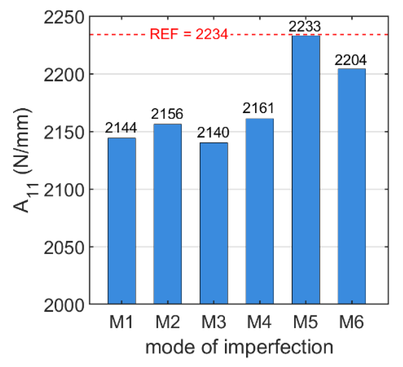
| 2234 | 2144 | 2156 | 2140 | 2161 | 2233 | 2204 | |
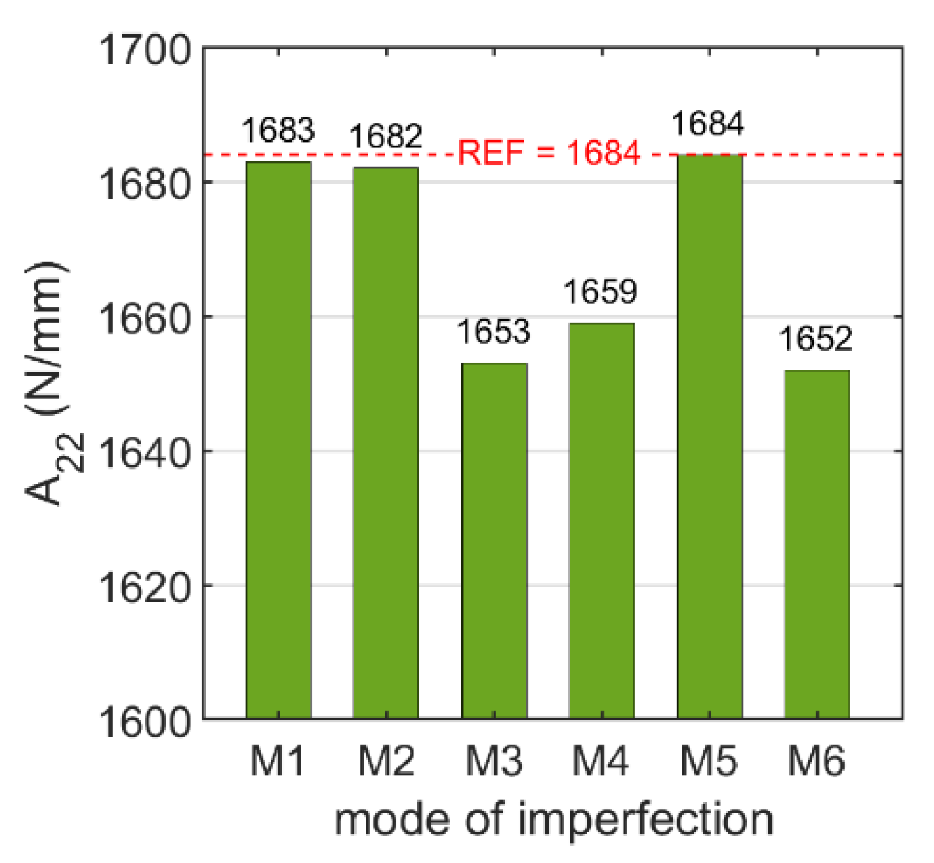
| 1684 | 1683 | 1682 | 1653 | 1659 | 1684 | 1652 | |
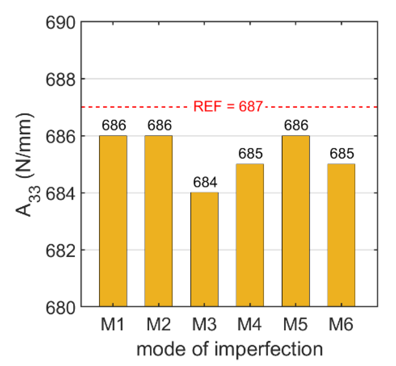
| 687 | 686 | 686 | 684 | 685 | 686 | 685 | |
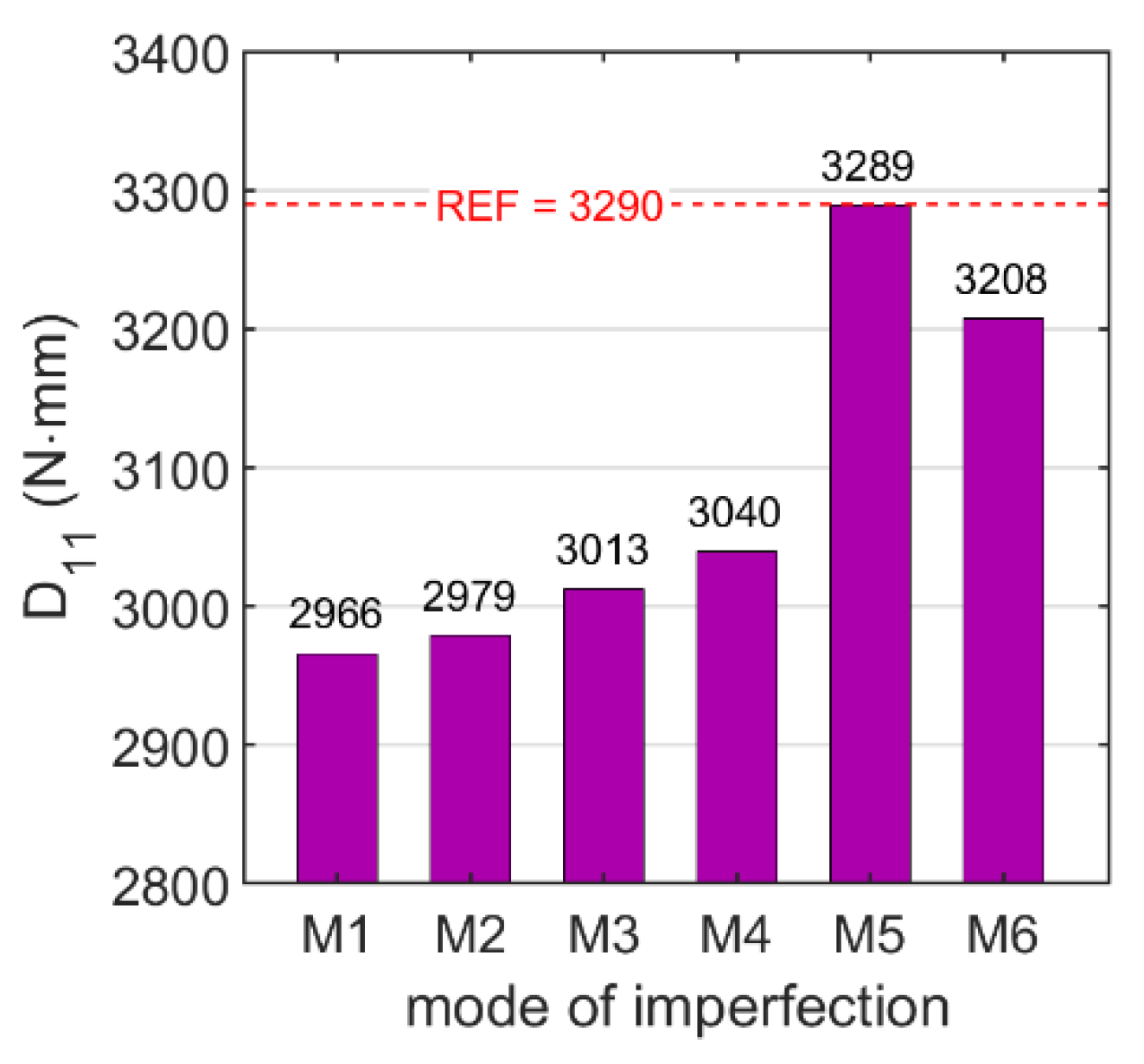
| 3290 | 2966 | 2979 | 3013 | 3040 | 3289 | 3208 | |
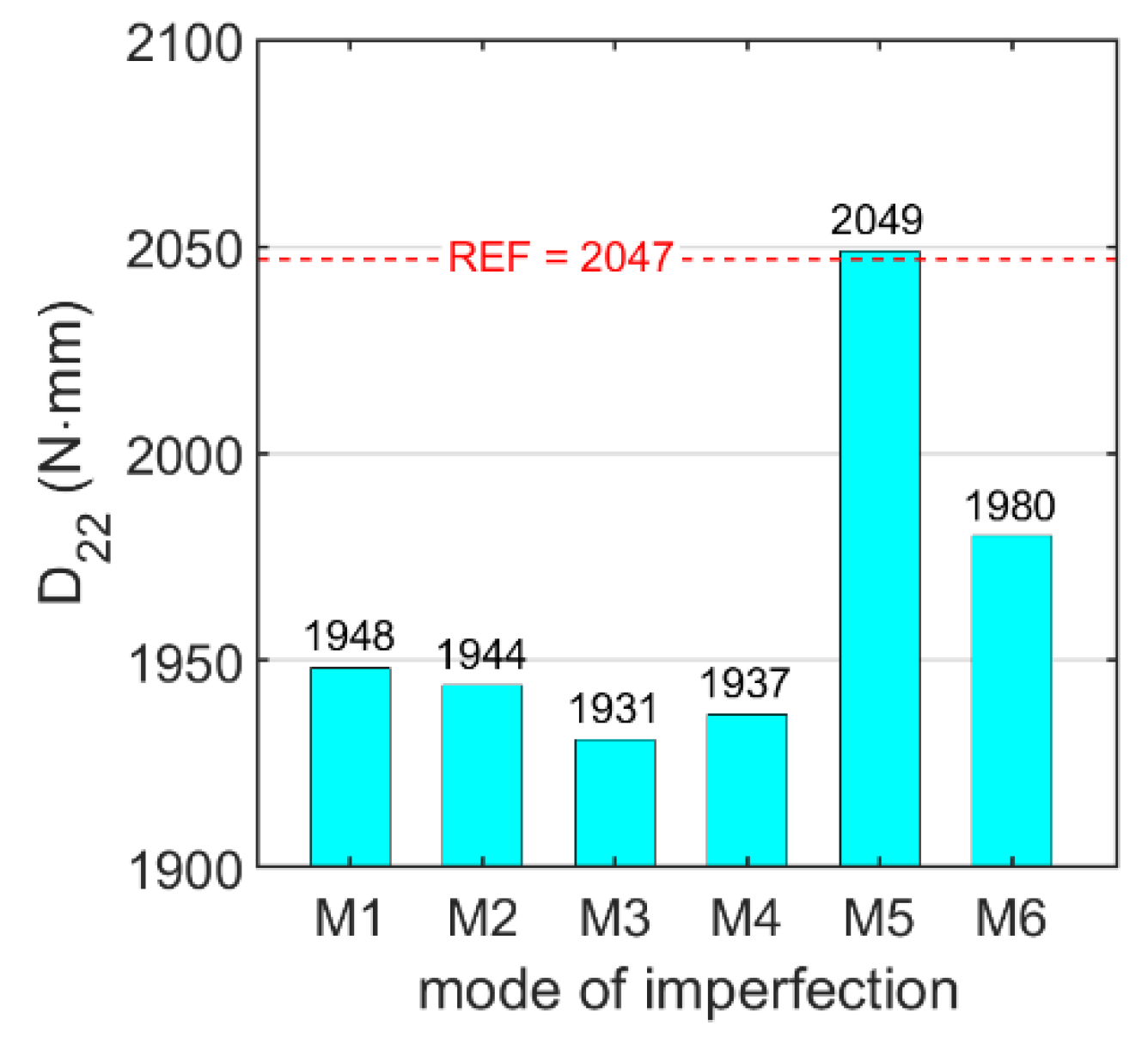
| 2047 | 1948 | 1944 | 1931 | 1937 | 2049 | 1980 | |
| 865 | 817 | 816 | 826 | 827 | 865 | 854 |
| M1 | M2 | M3 | M4 | M5 | M6 | |
|---|---|---|---|---|---|---|
| −4.0 | −3.5 | −4.2 | −3.3 | −0.06 | −1.4 | |
| −0.1 | −0.1 | −1.8 | −1.5 | −0.01 | −1.9 | |
| −0.1 | 0.0 | −0.5 | −0.2 | −0.03 | −0.2 | |
| −9.9 | −9.5 | −8.4 | −7.6 | −0.05 | −2.5 | |
| −4.8 | −5.1 | −5.7 | −5.4 | 0.07 | −3.3 | |
| −5.5 | −5.6 | −4.5 | −4.4 | 0.00 | −1.3 |
| Reference Stiffnesses | Final Stiffnesses | Stiffness Reduction (%) | |
|---|---|---|---|
| 2234 | 2144 | −4.0 | |
| 1684 | 1653 | −1.8 | |
| 687 | 686 | −0.03 | |
| 3290 | 2979 | −9.5 | |
| 2047 | 1937 | −5.4 | |
| 865 | 854 | −1.3 |
Publisher’s Note: MDPI stays neutral with regard to jurisdictional claims in published maps and institutional affiliations. |
© 2022 by the authors. Licensee MDPI, Basel, Switzerland. This article is an open access article distributed under the terms and conditions of the Creative Commons Attribution (CC BY) license (https://creativecommons.org/licenses/by/4.0/).
Share and Cite
Mrówczyński, D.; Knitter-Piątkowska, A.; Garbowski, T. Numerical Homogenization of Single-Walled Corrugated Board with Imperfections. Appl. Sci. 2022, 12, 9632. https://doi.org/10.3390/app12199632
Mrówczyński D, Knitter-Piątkowska A, Garbowski T. Numerical Homogenization of Single-Walled Corrugated Board with Imperfections. Applied Sciences. 2022; 12(19):9632. https://doi.org/10.3390/app12199632
Chicago/Turabian StyleMrówczyński, Damian, Anna Knitter-Piątkowska, and Tomasz Garbowski. 2022. "Numerical Homogenization of Single-Walled Corrugated Board with Imperfections" Applied Sciences 12, no. 19: 9632. https://doi.org/10.3390/app12199632
APA StyleMrówczyński, D., Knitter-Piątkowska, A., & Garbowski, T. (2022). Numerical Homogenization of Single-Walled Corrugated Board with Imperfections. Applied Sciences, 12(19), 9632. https://doi.org/10.3390/app12199632