Abstract
In this article, a novel and high-efficiency dual-wideband linear-to-circular polarization conversion based on a rectangular-slot reflective metasurface is anticipated, one that can convert linearly polarized (LP) electromagnetic waves into right- and left-hand circularly polarized waves in two non-adjacent frequency bands. The converter is an orthotropic design, with a pair of mutually orthogonal symmetric axes (u and v) along orientations tilted at 45° to the y-axis. The simulated results indicate that the dual-wideband circularly polarized wave is achieved under a y-polarized an electromagnetic (EM) incidence wave over the bands of 16.49–23.54 GHz and 26.44–34.56 GHz with 3 dB axial ratio relative bandwidths of 35.23% and 26.62%, respectively, and a polarization conversion ratio (PCR) in excess of 99%. A detailed mathematical investigation is proposed to determine the fundamental factor causing the dual-wideband linear-to-circular polarization conversion. The phase difference ( between ruu and rvv under u- and v- polarized incident waves is , and it entirely determines the 3 dB reflected wave axial ratio. Any reflective converter can work efficiently as a linear-to-circular polarization conversion if the phase difference ( is close to .
  1. Introduction
Controlling the polarization state of electromagnetic waves in real time is crucial because it is one of the basic characteristics of electromagnetic waves, which must be considered in real-world applications. Using a metasurface to complete an LTC polarization conversion is an effective technique that has drawn considerable interest. The relevance of realizing a circularly polarized wave has gradually increased as a field of interest. Recently, it has become very popular to modify polarization, optical activity, and birefringence using natural materials, particularly in devices such as quarter-wave plates or circular polarizers [,]. Nowadays, modern wireless communication systems increasingly use miniaturized antennas. Metamaterials and magnetic materials have been considered a potential artificial dielectric to alleviate wideband problems. By acting as electromagnetic wave power absorbers, metamaterials are used to eliminate unwanted frequencies (associated with frequency selective surfaces) that can be the root of undesirable electromagnetic waves coupling in microwave radar applications. The frequency selective surface was developed as a broadband reflector and applied to resolve many significant issues in numerous scientific domains. Additionally, the frequency selective surface is continually changing to satisfy increasing demand to extend bandwidth, which affects many contemporary applications, as well as telecoms, all of which depend on a particular bandwidth to operate. Therefore, cutting-edge technologies that can reliably produce a variety of signals throughout a broad band of frequencies are in high demand worldwide. Several procedures, including single-and multi-layer structures, have been considered to improve the efficiency of ultrawideband two-dimensional antennas via a frequency selective surface. The FSS single layer can be used as a reflector, similarly to partially reflecting surfaces (PRS), which transmit some frequencies (although they operate as bandpass filters) and reflect others (after operating as stopband filters). Polarizers have two types: transmissive and reflecting. For example, two separate polarizations received from two bands have been integrated with transmission-type circular polarizers to establish two distinct channels for up- and down-link satellite communications [,]. Circular polarization on both bands was intended for a radio frequency identification dual-band artificial magnetic conductor reflector []. Most research has been confined to a single purpose, revealing that the design can only regulate and alter LTC, cross conversion, and cross-polarization conversion as polarization in a single band. Recently, numerous polarization converters based on different metasurfaces and capable of conducting a diversity of polarization conversions have been anticipated, including: transmissive [,,,] and reflective [,,,,,,,,,] LTC polarization converters under linearly polarized incidence, reflective linearly polarized [,,,,,,,] or circularly polarized [,,,,], and transmissive linearly polarized [,,,,] or circularly polarized [,,] incidence. Moreover, using the previously mentioned LTC polarization converters still poses problems in achieving the desired characteristics of an ultrawideband: high efficiency and compact design.
Additionally, Liu et al. created a dual-band transmission LTC polarization converter with angular stability via a metasurface. While the working frequency bands for these two polarization converters are 9.05–9.65 GHz and 12.55–13.1 GHz, respectively, both have relative bandwidths of only 6.0% and 4.0% []. Recently, Majeed et al. reported an ultrawideband LTC polarization conversion using a circular pie-shaped reflective metasurface, with a theoretical 3dB axial ratio relative bandwidth of 50.8% []. On the other hand, in the THz region, Ghosh et al. presented a reflective linear-to-circular polarization converter based on a graphene metasurface that can perform between 3.75 THz and 6.0 THz with a 46.15% relative bandwidth []. Additionally, Wang et al. presented a dual-band linear-to-circular polarization converter with wide-angle and wideband axial ratio, constructed on a three-metallic-layer reflective metasurface. This has a 3 dB axial ratio over the lower-frequency bandwidth of 15–21.2 GHz (34.3%)/16.3–21.1 GHz (25.7%) and higher-frequency bandwidth of 27–30.3 GHz (11.5%)/27–29.8 GHz (9.9%) but has a poor PCR []. A further example is that of Gao et al., who demonstrated the result of a bilayered metasurface via an ultrawideband LTC polarization converter [].
This article proposes a high-efficiency dual-frequency wideband LTC polarization converter based on a single-layer reflective metasurface. The proposed converter can convert linearly polarized electromagnetic waves over the dual-frequency bands of 16.49–23.54 GHz and 26.44–34.56 GHz into right- and left-handed circularly polarized (RHCP/LHCP) waves under a y-polarized incident wave. The physical interpretation is given, and the efficiency is evaluated by a mathematical equation. The execution of parametric analysis provides design specifications for various frequency ranges. We employ simulations, mathematical operations, and comprehensive theoretical analysis of the dual-frequency wideband and high-efficiency LTC polarization conversion to corroborate the proposed polarization converter.
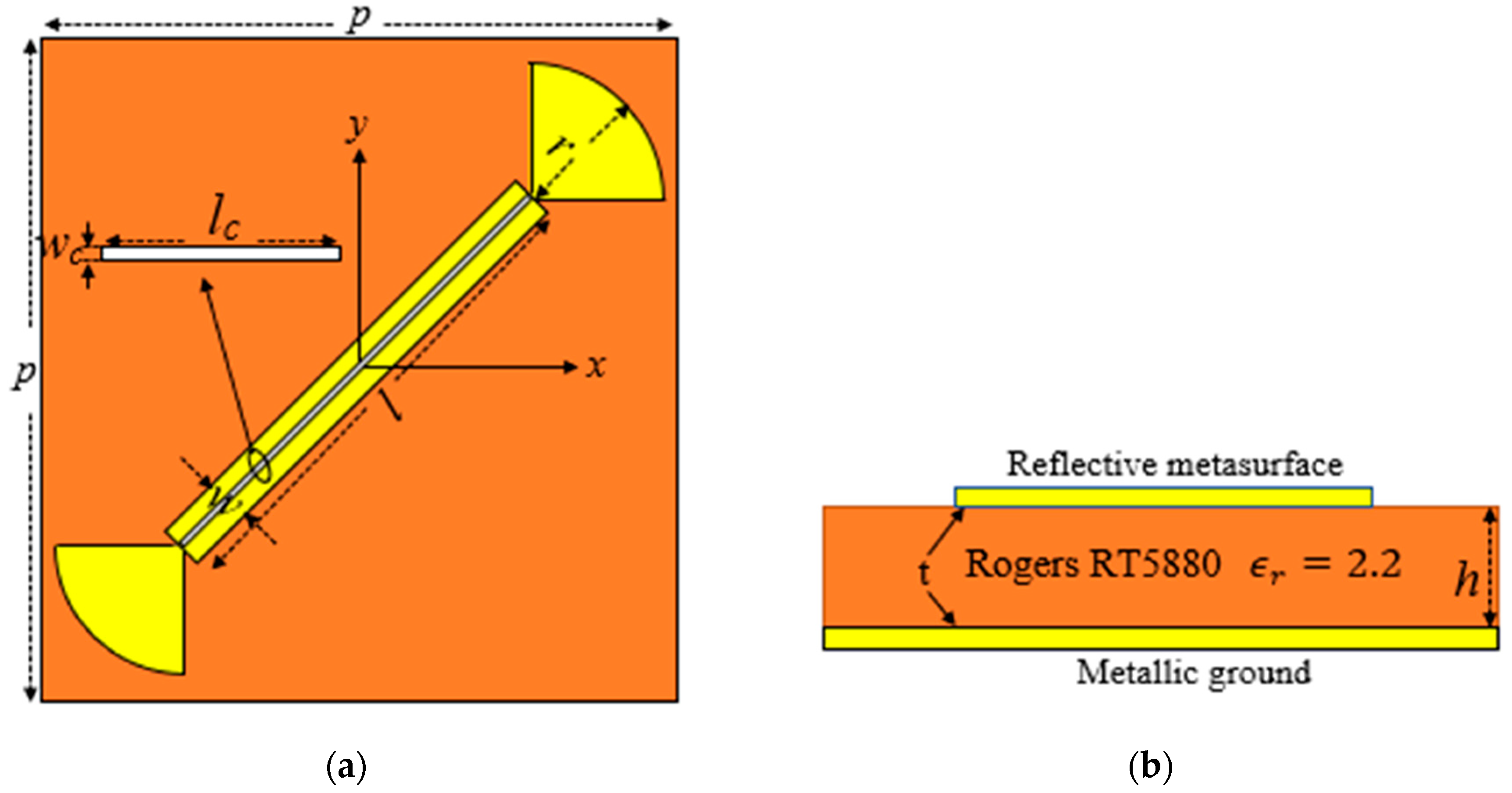
2. Metasurface Design and Simulation
The schematic design of the proposed converter is presented in Figure 1. The proposed converter is mainly composed of a rectangular patch embedded with a rectangular slot and with two radial stubs separated from a ground plane by a dielectric spacer Roger RT5880 with the property of , h = 1.6 mm and tangent loss of . The metallic ground plane and proposed unit cell are modeled using a copper sheet with an electrical conductivity of σ = 5.8 ×  S/m and a thickness of 0.017 mm. The other physical parameters are tabulated in Table 1. According to Figure 1, the rectangular slot is inserted in the middle of the rectangular patch at a 45° rotational angle. We execute a series of simulations using CST Microwave Studio to evaluate the dual-wideband reflective linear-to-circular polarization converter efficiency. The XY boundary conditions are constrained by the unit cell, and a Floquet port is excited on the z-axis. Figure 2 shows the simulation results when a normal-incidence y- or x-polarized wave is set as an input. The reflection coefficient’s magnitudes of the cross- and co-polarization are rxy and ryy, associated with a phase difference. The phase difference () between ryy and rxy exists due to the anisotropic features of the metasurface. An efficient reflective LTC polarization converter can be designed if  and  (k = 0, 1, 2…), where the sign (±) represents the RHCP () and LHCP () of the reflected wave. According to Figure 2a, the magnitudes of ryy and rxy of the dual-band LTC polarization converter based on the rectangular slot reflective metasurface are nearly equal over the frequency ranges of 17.67–21.14 GHz and 28.36–32.91 GHz. According to Figure 2b, the phase difference between the 15–24.22 GHz and 25.50–37 GHz frequency bands is always close to −90°, and satisfies the phase relation (). The reflected wave can be considered circularly polarized if its axial ratio is below 3 dB. To calculate the bandwidth of the anticipated dual-wideband polarization conversion, we computed the axial ratio of the reflected wave from the succeeding equation, using the data set presented in Figure 2 [].


    Figure 1.
      Unit cell of the proposed reflective converter. (a) Top view of the rectangular-slot polarization converter with physical parameters and (b) side view with substrate properties.


    Table 1.
    Optimized value (in mm) of the reflective metasurface unit cell.


    Figure 2.
      The simulated results of the proposed converter. (a) The magnitudes (ryy and rxy) and (b) phase difference (∆φyx).
  
The calculated axial ratio of the proposed converter exists below 3 dB over the dual-frequency wideband of 16.49–23.54 GHz and 26.44–34.56 GHz, as presented in Figure 3a. The 3 dB axial ratio bandwidth within dual-frequency wideband of 16.49–23.54 GHz and 26.44–34.56 GHz is 35.23% and 26.62%, respectively. Additionally, the axial ratio is kept under 1.5 dB, demonstrating that the polarization conversion ratio of the polarization converter is above 99%. Other parameters, called reflection coefficients of the LTC polarization converter (RHCP and LHCP), a polarization conversion ratio, and a polarization extinction ratio are introduced [] to evaluate a linear-to-circular polarization conversion with a promising procedure. We established these parameters of the reflected wave from the following equations, applying the results simulated above.


    Figure 3.
      The calculated results of the proposed rectangular-slot converter under y-polarized incidence. (a) Axial ratio (dB) and (b)  and  (dB).
  
The reflection coefficients of the dual-frequency wideband LTC polarization converter are determined using Equation (2) based on the data simulated above. As shown in Figure 3b, the calculated dual-frequency wideband  magnitude is close to 0 dB with respect to 3 dB axial ratio, indicating that the reflected wave under the normal incidence y-polarized wave has converted to an RHCP and LHCP wave. Furthermore, the obtained dual-frequency wideband polarization conversion ratio, illustrated in Figure 4a, thoroughly shows that the linear-to-circular polarization conversion ratio can be accomplished at more than 99% over the frequency ranges of 17–23.07 GHz and 27.01–33.70 GHz, respectively, conquering 35.23% and 26.62% of the 3 dB axial ratio band. The effectiveness of circular polarization is determined by the polarization extinction ratio (PER) between  and  waves. The polarization extinction ratio should be greater than −20 dB (LHC) or +20 dB (RHCP) to establish the equal 90° phase difference and magnitude succeeding in a circularly polarized wave. According to Figure 4b the frequency bands between 16.01–23.95 GHz and 24.85–37.0 GHz meet the polarization extinction ratio requirement. The efficiency of the proposed polarization converter is significantly higher with the polarization conversion ratio and polarization extinction ratio frequency bands, which hold 35.23% and 26.62% of the 3 dB axial ratio over the dual-frequency bands of 16.49–23.54 GHz and 26.44–34.65 GHz, respectively. In summation, a normal y-polarized incident wave can be converted into a circularly polarized wave using the proposed converter, which has an exceptionally wide band and is highly efficient.
      
    
    Figure 4.
      The calculated results of proposed converter under y-polarized incidence. (a) Linear-to-circular polarization conversion ratio (%) and (b) polarization extinction ratio (dB).
  
Parameters Analysis
The aim of this section is to investigate how different parameters influence the phase difference and 3 dB axial ratio of the dual-frequency wideband linear-to-circular polarization conversion. To achieve an optimal parameter, we optimized the values of the radial stub (r) and the width of the rectangular patch (w). A sequence of parametric simulations was performed to evaluate the influence of the parameters on the phase difference and 3 dB axial ratio of the converter unit cell when one parameter was changed while the other stayed the same. The calculated results of the parametric phase difference and 3 dB axial ratio of the dual-frequency wideband LTC polarization conversion are shown in Figure 5 and Figure 6. The phase difference of a perfect linear-to-circular polarization converter can be calculated [] from the succeeding equation:


        where k is an integer, and the negative  and positive  signs represent the RHCP and LHCP, respectively. According to our calculation results, changing the radius of the stub and width of the rectangular patch of a dual-wideband LTC polarization conversion does not influence the phase difference, as shown in Figure 5a,b. The phase difference is ° and  in the frequency range of  GHz and  GHz, respectively, which satisfies Equation (5), as demonstrated in Figure 5.
      
    
    Figure 5.
      The simulated parametric result of phase difference (degree) at y-polarized incidence. (a) r (0.84 mm to 0.90 mm) and (b) w (0.54 mm to 0.60 mm).


    Figure 6.
      The simulated parametric results of axial ratio (dB) at y-polarized incidence. (a) r (0.84 mm to 0.90 mm) and (b) w (0.54 mm to 0.60 mm).
  
The 3 dB axial ratio of a dual-frequency wideband is influenced by changing the parametric values of the radial stub and width of the rectangular patch, as shown in Figure 6a,b. The resonance peak of the 3 dB axial ratio of a dual-frequency wideband linear-to-circular polarization converter at the lower and higher frequency range was less than 3 dB after increasing the radius of the stub and width of the rectangular patch from 0.84 to 0.90 mm and 0.54 to 0.60 mm, as shown in Figure 6a,b. The parameter ranges r and w shown in Figure 6 were selected to follow the 3 dB axial ratio (0.84 mm–0.90 mm and 0.54 mm–0.60 mm). When the parameters are changed, it is interesting to see that the axial ratio exists below 3 dB. The preceding explanation explains why our proposed reflective metasurface excels in dual-wideband linear-to-circular polarization conversion.
3. Theoretical Analysis
The anticipated reflective converter performs a dual-frequency wideband LTC polarization conversion with high efficiency and as an ultrawideband. In the following analysis, we conduct a thorough theoretical investigation to achieve a complete physical configuration of the fundamental root. There would not be any cross-polarized reflecting factors under u- and v-polarized waves because it is a symmetric configuration with two mutually orthogonal symmetric axes. The reflection matrix (Rlin) is due to a linearly polarized (LP) incident wave in the uv-local coordinate system, and can be written as []: 


Since the metasurface structure is anisotropic, the reflection coefficients of the co-polarization, i.e., , , will be independent of one another, but the magnitudes of co-polarization reflection coefficients will be relatively near to 1.0 because of the minimal dielectric loss. Thus the succeeding equation can be acknowledged without considering the minimal dielectric loss: . The reflection coefficients  and  have a phase difference which can lie between  and  Moreover, the symmetrical axes v- and u- are oriented in the same direction as the y-axis and have a  tilt angle. The x- and y-polarized waves can be characterized using the uv- coordinates as  and , respectively. In the xy-coordinate system, the Rlin can be computed via Equation (6). If a normal incidence y-polarized wave is supposed as an input (), the reflected wave can be differentiated as follows: , via Equation (6). Following algebraic simplification, the reflected wave can be expressed as . The reflection coefficients of co-() and cross- () polarization for the normal-incidence y-polarized wave can be written as  and . After a similar computation for the x-polarized wave, the final form of Rlin in the xy-coordinate system can be derived using [], as shown below:


From Equation (7), the succeeding equation can be derived as: 


Moreover, using Equation (8), the magnitudes of co-polarized reflection coefficients ) and cross-polarized reflection coefficients () can be written as follows:


The reflection coefficients of  and -polarization with x- and y-polarized incidence waves are pure imaginary numbers. It is always supposed that the  between them is  It clarifies that in Figure 2b, the  is always  for the dual-frequency bands of 15–24.22 GHz and 25.50–37.0 GHz. When the  the polarization reflection coefficients of the () and () will not be zero, resulting in an elliptical polarized reflected wave, with a phase difference between the () and ( remaining ±90°. The 3 dB axial ratio of the reflected wave using the magnitude ratio of () and () can be found from [] and is given below:


Moreover, Equation (8) has been applied to the relationship , indicating that the ratio of the cross (y- to -x and x- to -y)-polarization reflection coefficient under y- and x-polarized incidences is always equal, which concludes that an isotropic metasurface converts a normal incidence y-polarized wave to right- and left-hand circular polarized reflected waves. When ∆φuv = 0°, , Equation (9) implies that the polarization condition of the incident and reflected wave will be equal. When ∆φuv = 180°, however,  to achieve a perfect cross-polarization. Additionally, when , the reflected wave will be elliptically polarized, and the reflected wave’s axial ratio can be determined using the succeeding equation:


Here, the () and () signs ensure that the axial ratio will never be less than 1.0, according to Equation (11). The axial ratio of the reflected wave is equal to 1.0 at ∆φuv = 90°, which indicates a perfect LTC reflective polarization converter, according to Equations (10) and (11). When ∆φuv = 90°, the perfect LTC reflective polarization conversion can be realized. The incident wave and reflected wave under x- and y-polarization can be considered a composite wave with equal magnitude u- and v-polarized components to negligible dielectric loss. Both orthogonal components appear to be in phase with one another in the incident wave, but the ∆φuv between them will change in the reflected wave. The ∆φuv will be altered to  when ∆φuv = 90°, resulting in a perfect LTC polarization conversion. We used the preceding study to simulate the anticipated polarization reflective converter under v- and u-polarized incidence to determine the fundamental cause of linear-to-circular polarization converters. The simulated results of a dual-frequency wideband LTC polarization, especially the ∆φuv (phase difference) between rvv and ruu, are shown in Figure 7a. The frequency bands between 16.27–23.79 GHz and 27–35.23 GHz show that the phase difference of a dual-frequency wideband always remains close to  It is implied that the calculated LTC-polarization converter of a dual-wideband will be comprehended in a wide frequency range. Why is the resulting phase difference (∆φuv) so effective? To ensure the root cause, the other simulation results, such as the magnitude (ruu and rvv) along with the phases (φuu and φvv) of a dual-wideband, are presented in Figure 7b,c. The formula φii = Arg(Rii) + 2k0 S is applied to determine their phase changes, where S is the separation between the proposed converter surface and the Floquet port in the simulation structure. According to Figure 7b, the magnitude of a dual-frequency wideband is nearly 1.0 throughout all frequencies, indicating minimal dielectric loss of the proposed polarization converter. The curve of rvv and ruu still has a great many variations, which have two and two in dual-frequency wideband local minimum values, respectively, which are found at 13.56 GHz and 40.24 GHz, as well as at 24.94 GHz and 40.65 GHz. The two and two in dual-wideband resonant modes are assumed to be simulated by v- and u-polarized incident waves, created by these local maximum dielectric losses. Additionally, the curves of ruu and rvv have quite distinct curvatures at various resonant frequencies, suggesting that the Q values of these resonant modes vary. Moreover, Figure 7c shows that the phase variation rate of rvv and ruu at each resonance frequency varies only due to the variance in Q values across different resonance modes. At a lower frequency, the phase difference ∆φuv can remain close to +90° over the frequency band of 16.27–23.79 GHz, whereas at a higher frequency it is an integral multiple of 90° (in the frequency band of 27–35.23 GHz), which is primarily due to the following two causes. Firstly, compared to the first resonance mode (13.56 and 24.94 GHz) at v- and u-polarized incident in a dual-frequency wideband, it has a higher Q value in addition to possessing a lower resonant frequency. It causes the phase φvv in a dual-wideband to decline earlier and more quickly, and, when keeping the phase difference (∆φuv) in the 11–13.75 GHz range, is close to +90°. Secondly, the second pair of  resonant modes in a dual-frequency wideband at v- and u-polarized incidences are identical, and both are very clear. This causes the phases of φuu and φvv to change the same way as the frequency increase in the range of 15–39 GHz, allowing the phase difference (∆φuv) is close to +90° or an integral multiple of  It is implied that the calculated LTC-polarization converter of a dual-wideband will be comprehended in a wide frequency range. Why is the resulting phase difference (∆φuv) so effective? To ensure the root cause, the other simulation results, such as the magnitude (ruu and rvv) along with the phases (φuu and φvv) of a dual-wideband, are presented in Figure 7b,c. The formula φii = Arg(Rii) + 2k0 S is applied to determine their phase changes, where S is the separation between the proposed converter surface and the Floquet port in the simulation structure. According to Figure 7b, the magnitude of a dual-frequency wideband is nearly 1.0 throughout all frequencies, indicating minimal dielectric loss of the proposed polarization converter. The curve of rvv and ruu still has a great many variations, which have two and two in dual-frequency wideband local minimum values, respectively, which are found at 13.56 GHz and 40.24 GHz, as well as at 24.94 GHz and 40.65 GHz. The two and two in dual-wideband resonant modes are assumed to be simulated by v- and u-polarized incident waves, created by these local maximum dielectric losses. Additionally, the curves of ruu and rvv have quite distinct curvatures at various resonant frequencies, suggesting that the Q values of these resonant modes vary. Moreover, Figure 7c shows that the phase variation rate of rvv and ruu at each resonance frequency varies only due to the variance in Q values across different resonance modes. At a lower frequency, the phase difference ∆…uv can remain close to +90° over the frequency band of 16.27–23.79 GHz, whereas at a higher frequency it is an integral multiple of 90° (in the frequency band of 27–35.23 GHz), which is primarily due to the following two causes. Firstly, compared to the first resonance mode (13.56 and 24.94 GHz) at v- and u-polarized incident in a dual-frequency wideband, it has a higher Q value in addition to possessing a lower resonant frequency. It causes the phase φvv in a dual-wideband to decline earlier and more quickly, and, when keeping the phase difference (∆φuv) in the 11–13.75 GHz range, is close to +90°. Secondly, the second pair of  resonant modes in a dual-frequency wideband at v- and u-polarized incidences are identical, and both are very clear. This causes the phases of φuu and φvv to change the same way as the frequency increase in the range of 15–39 GHz, allowing the phase difference (∆φuv) is close to +90° or an integral multiple of  in the following band. Finally, Figure 7d shows the axial ratio of the reflected wave via Equation (10), based on the phase difference (∆φuv) in a dual-frequency wideband obtained in Figure 7a. It is evident from Figure 3a that the anticipated axial ratio substantially agrees with Figure 7d. The above analysis has clarified that the polarization converter in a dual-frequency wideband can carry out such a high-efficiency and ultrawideband LTC reflective polarization conversion. Excluding the first two resonant modes at v- and u-polarized incidences, it can be generally ascribed to the second pair of resonance modes. A sufficient difference between the two first resonance modes causes the ∆φuv in the frequency range of 10–15 GHz to be close to . However, due to the similarity and low Q values of the second pair of resonance modes, the phase difference (∆φuv) remains nearby ° or an integral multiple of  in the adjacent band of 16.27–23.79 GHz and 27.0–35.23 GHz. Comparisons of the performance of this novel LTC reflective polarization conversion metasurface in a dual-wideband with those in previously published papers are tabulated in Table 2. Hence, the calculated LTC polarization conversion of 99 % of a dual-frequency wideband has been achieved in the ultrawideband frequency range.
      
    
    Figure 7.
      The simulated results of the proposed converter at u-and v-polarized incidences. (a) Phase difference (∆φuv); (b) The magnitudes of ruu and rvv; (c) Phase (φuu and φvv); (d) Axial ratio (dB).


    Table 2.
    Comparative study of LTC polarization conversion of the proposed metasurface with the previously published works.
  
4. Conclusions
In summary, a dual-frequency wideband LTC polarization conversion based on a reflective metasurface is presented in this article. The proposed converter can convert EM-waves into RHCP and LHCP in a dual non-adjacent frequency band of 16.49–23.54 GHz and 26.44–34.56 GHz, which corresponds to the relative bandwidths 35.23% and 26.62%, respectively, according to the 3 dB axial ratio property. Moreover, a comprehensive theoretical investigation is proposed to get a physical insight into the underlying cause of the LTC polarization converter. It can be related mainly to the second pair of resonance modes, which keep ∆φuv = +90° or an integral multiple of −90° in a dual and ultrawideband frequency range of 16.27–23.79 GHz and 27–35.23 GHz. Any reflective converter can be operated as a dual-frequency wideband LTC polarization conversion if the ∆φuv between ruu and rvv is close to ±90° or an odd integral multiple of ±90°. 
Author Contributions
Writing—original draft preparation, A.M.; writing—review and editing, J.Z. and C.W.; methodology, A.M.; software, A.M.; formal analysis, Z.A.A.; validation, M.I.; investigation, C.W.; data curation, S.M. All authors have read and agreed to the published version of the manuscript.
Funding
This work was supported by the Fundamental Research Funds for the Central Universities (No. 2019XD-A07), the National Nature Science Foundation of China (Grant No. 62271063), the director Fund of Beijing Key Laboratory of Space-ground Interconnection and Convergence and the National Key Laboratory of Science and Technology on Vacuum Electronics.
Institutional Review Board Statement
Not applicable.
Informed Consent Statement
Not applicable.
Data Availability Statement
Not applicable.
Conflicts of Interest
The authors declare no conflict of interest.
References
- Deng, Y.; Cai, Z.; Ding, Y.; Bozhevolnyi, S.I.; Ding, F. Recent progress in metasurface-enabled optical waveplates. Nanophotonics 2022, 11, 2219–2244. [Google Scholar] [CrossRef]
 - Ding, F.; Tang, S.W.; Bozhevolnyi, S.I. Recent advances in polarization-encoded optical metasurface. Adv. Photon. Res. 2021, 2, 2000173. [Google Scholar] [CrossRef]
 - Wang, H.; Yang, P.; Qin, H.; Dang, R. The broadband interconnected receiver-transmitter surface for generating dual circularly polarized dual beams. AIP. Adv. 2022, 12, 025003. [Google Scholar] [CrossRef]
 - Nama, L.; Nilotpal, S.; Bhattacharyya; Jain, P.K. A metasurface-based, ultra-thin, dual-band, linear-to-circular, reflective polarization converter: Easing up-linking and down linking for wireless communication. IEEE Antennas Propag. Mag. 2021, 63, 100–110. [Google Scholar] [CrossRef]
 - Sarkar, S.; Gupta, B. A dual-band circularly polarized antenna with a dual-band AMC reflector for RFID readers. IEEE Antennas Wirel. Propag. Lett. 2020, 19, 796–800. [Google Scholar] [CrossRef]
 - Liu, K.; Wang, G.; Cai, T.; Li, T. Dual-band transmission circular polarization generator with high angular stability. Opt. Express 2020, 28, 14995. [Google Scholar] [CrossRef] [PubMed]
 - Majeed, A.; Zhang, J.; Ashraf, M.A.; Memon, S.; Mohammadani, K.H.; Ishfaq, M.; Sun, M. An ultra-wideband linear-to-circular polarization converter based on a circular, pie-shaped reflective metasurface. Electronics 2022, 11, 1681. [Google Scholar] [CrossRef]
 - Lin, B.; Liv, L.; Guo, J.; Liu, Z.; Ji, X.; Wu, J. An ultra-wideband reflective linear-to-circular polarization converter based on anisotropic metasurface. IEEE Access 2020, 8, 82732–82740. [Google Scholar] [CrossRef]
 - Dutta, R.; Ghosh, J.; Yang, Z.; Zhang, X. Multi-band multifunctional metasurface-based reflective polarization converter for linear and circular polarizations. IEEE Access 2021, 9, 152738–152748. [Google Scholar] [CrossRef]
 - Liao, K.; Liu, S.; Zheng, X.; Zhang, X.; Shao, X.; Kong, X.; Hao, Z. A polarization converter with single-band linear-to-linear and dualband linear-to-circular based on single-layer reflective metasurface. Int. J. RF Microw. Comp. Aided. Eng. 2022, 2, e22955. [Google Scholar]
 - Greco, F.; Arnieri, E. Dual-frequency linear-to-circular polarization converter for Ka-band applications. Sensors 2022, 22, 2187. [Google Scholar] [CrossRef]
 - Wang, H.B.; Cheng, Y.J.; Chen, Z.N. Dual-band miniaturized linear-to-circular metasurface polarization converter with wideband and wide-angle axial ratio. IEEE Trans. Antennas Propag. 2021, 69, 9021–9025. [Google Scholar] [CrossRef]
 - Memon, S.; Wang, J.; Bhangwar, A.R.; Fati, S.M.; Rehman, A.; Xu, T.; Zhang, L. Temperatur e and reliability-aware routing protocol for wireless body area network. IEEE Access 2021, 9, 140413–140423. [Google Scholar] [CrossRef]
 - Lin, B.-Q.; Huang, W.-Z.; Lv, L.-T.; Guo, J.-X.; Huang, S.-Q.; Zhu, R. An ultra-wideband linear-to-circular polarization conversion realized by an 8-shaped metasurface. Plasmonics 2021, 62, 629–634. [Google Scholar] [CrossRef]
 - Zhu, S.; Zhao, G.; Yan, Z.; Wang, Y.; Zhou, H. Ultra-wideband and wide-angle linear-to-circular polarizer based on single-layer dielectric substrates. Appl. Phys. A. 2021, 127, 821. [Google Scholar] [CrossRef]
 - Gao, X.; Li, K.; Wu, X.; Xue, C.; Wang, G.; Xie, X.; Qin, M. Ultra-wideband linear-to-circular polarizer realized by Bi-layer metasurface. Opt. Express 2022, 30, 18392–18401. [Google Scholar] [CrossRef]
 - Ghosh, S.K.; Das, S.; Bhattacharyya, S. Terahertz wave conversion from linear-to-circular polarization by graphene metasurface featuring ultrawideband tunability. J. Lightwave. Technol. 2022, in press. [Google Scholar] [CrossRef]
 - Jiang, S.C.; Xiong, X.; Hu, Y.S.; Hu, Y.H.; Ma, G.B.; Peng, R.W.; Sun, C.; Wang, M. Controlling the polarization state of light with a dispersion-free metasurface. Phys. Rev. X 2014, 4, 021026. [Google Scholar]
 - Zhang, Z.; Cao, X.; Gao, J.; Li, S. Broadband metamaterial reflector for polarization manipulation based on cross/ring resonators. Radioengineering 2016, 25, 436–441. [Google Scholar] [CrossRef]
 - Roy, K.; Rashmi, S.; Chetan, B. Linear-to-linear polarization conversion using metasurface for X, Ku and K band applications. Frequenz 2022, 76, 461–470. [Google Scholar] [CrossRef]
 - Tamim, A.M.; Hassan, M.M.; Faruque, M.R.I. Highly efficient metasurface polarization converter at Far-Infrared range. Front. Phys. 2022, 10, 314. [Google Scholar] [CrossRef]
 - Wang, X.; Yang, G. Linear polarization metasurface converter with an arbitrary polarization rotating angle. Opt. Express. 2021, 29, 30579–30589. [Google Scholar] [CrossRef] [PubMed]
 - Wu, X.; Cao, H.; Meng, Z.; Sun, Z. Ultra-broadband Pancharatnam-Bery phase metasurface for arbitrary rotation of linear polarization and beam splitter. Opt. Express 2022, 30, 15158–15171. [Google Scholar] [CrossRef] [PubMed]
 - Pouyanfar, N.; Nourinia, J.; Ghobadi, C. Multiband and multifunctional polarization converter using an asymmetric metasurface. Sci. Rep. 2021, 11, 9306. [Google Scholar] [CrossRef] [PubMed]
 - Karamirad, M.; Ghobadi, C.; Nourinia, J. Metasurfaces for wideband and efficient polarization rotation. IEEE. Trans. Antennas. Propag. 2021, 69, 1799–1804. [Google Scholar] [CrossRef]
 - Ahmed, F.; Khan, M.I.; Tahir, F.A. A multifunctional polarization transforming metasurface for C,-X,-K-band applications. IEEE Trans. Wireless. Propag. Lett. 2021, 20, 2186–2190. [Google Scholar] [CrossRef]
 - Gao, W.-H.; Chen, M.; Cheng, Q.; Cui, T.-J. A 1-bit coding metasurface with polarization conversion in X-band. Front. Mater. 2022, 9, 914937. [Google Scholar] [CrossRef]
 - Tutar, F.; Ozturk, G. An effective metasurface-based linear and circular polarization converter for C-and K-band application. Opt. Mater. 2022, 128, 112355. [Google Scholar] [CrossRef]
 - Bikkuri, P.; Sudhakar, A. Design of low profile multiband reflective polarization converter for both linear and circular polarized waves. Prog. Electromagn. Res. Lett. 2021, 97, 61–68. [Google Scholar] [CrossRef]
 - Ozturk, G. Ultra-thin, wide-angle and bandwidth-enhanced linear and circular metasurface-based reflection-type polarization converter at X-band microwave frequency. J. Electromag. Wave Appl. 2022, 36, 1423–1435. [Google Scholar] [CrossRef]
 - Khan, M.I.; Chen, Y.; Hu, B.; Ullah, N.; Bukhari, S.H.R.; Iqbal, S. Multiband linear and circular polarization rotating metasurface based on multiple plasmonic resonances for C, X and K-band applications. Sci. Rep. 2020, 10, 17981. [Google Scholar] [CrossRef]
 - Shah, S.M.Q.A.; Shoaib, N.; Ahmed, F.; Alomainy, A.; Quddious, A.; Nikolaou, S.; Imran, M.A.; Abbasi, Q.H. A multiband circular polarization selective metasurface for microwave applications. Sci. Rep. 2021, 11, 1774. [Google Scholar] [CrossRef] [PubMed]
 - Kundu, D.; Bhattacharyya, D.; Pathak, D. Simultaneous transmission and reflection mode linear-to-circular polarization conversion using a single metasurface. In Proceedings of the 2021 IEEE Indian Conference on Antennas and Propagation (InCAP), Jaipur, Rajasthan, India, 13–16 December 2021; pp. 591–594. [Google Scholar]
 - You, X.; Rajour, T.-A.; Wendy, S.L.; Bhaskaran, M.; Sriram, S.; Fumeaux, C.; Withayachumnankul, W. Terahertz transmissive half-wave metasurface with enhanced bandwidth. Opt. Lett. 2021, 46, 4164–4167. [Google Scholar] [CrossRef] [PubMed]
 - You, X.; Rajour, T.-A.; Wendy, S.L.; Bhaskaran, M.; Sriram, S.; Fumeaux, C.; Withayachumnankul, W. Broadband terahertz transmissive quarter-wave metasurface. APL Photonics 2020, 5, 096108. [Google Scholar] [CrossRef]
 - You, X.; Fumeaux, C.; Withayachumnankul, W. Tutorial on broadband transmissive metasurface for wavefront and polarization control of terahertz waves. J. Appl. Phys. 2020, 131, 061101. [Google Scholar] [CrossRef]
 - Ghosh, S.K.; Das, S.; Bhattacharyya, S. Transmittive-type triple- band linear to circular polarization conversion in THz region using graphene-based metasurface. Optic. Commun. 2021, 480, 126480. [Google Scholar] [CrossRef]
 - Liu, Y.; Yang, H.; Huang, X.; Yu, Z.; Li, S.; Yang, Y. A metamaterial polarization converter with half reflection and transmission simultaneously. Phys. Lett. A 2021, 389, 127101. [Google Scholar] [CrossRef]
 - Yuan, L.; Hou, L.; Yang, Z.; Zhang, Z. Triple-band ultra-thin linear to circular polarization converter based on transmission metasurface. Microw. Opt. Technol. Lett. 2022, 62, 54–59. [Google Scholar] [CrossRef]
 - Khan, M.I.; Hu, B.; Chen, Y.; Ullah, N.; Khan, M.J.I.; Khalid, A.R. Multiband efficient asymmetric transmission with polarization conversion using chiral metasurface. Microw. IEEE Antennas Wirel. Propag. Lett. 2020, 19, 1137–1141. [Google Scholar] [CrossRef]
 
Publisher’s Note: MDPI stays neutral with regard to jurisdictional claims in published maps and institutional affiliations.  | 
© 2022 by the authors. Licensee MDPI, Basel, Switzerland. This article is an open access article distributed under the terms and conditions of the Creative Commons Attribution (CC BY) license (https://creativecommons.org/licenses/by/4.0/).