
Generation of High-Density Pulsed Gas–Liquid Discharge Plasma Using Floating Electrode Configuration at Atmospheric Pressure
 ,
, 
Abstract
:1. Introduction
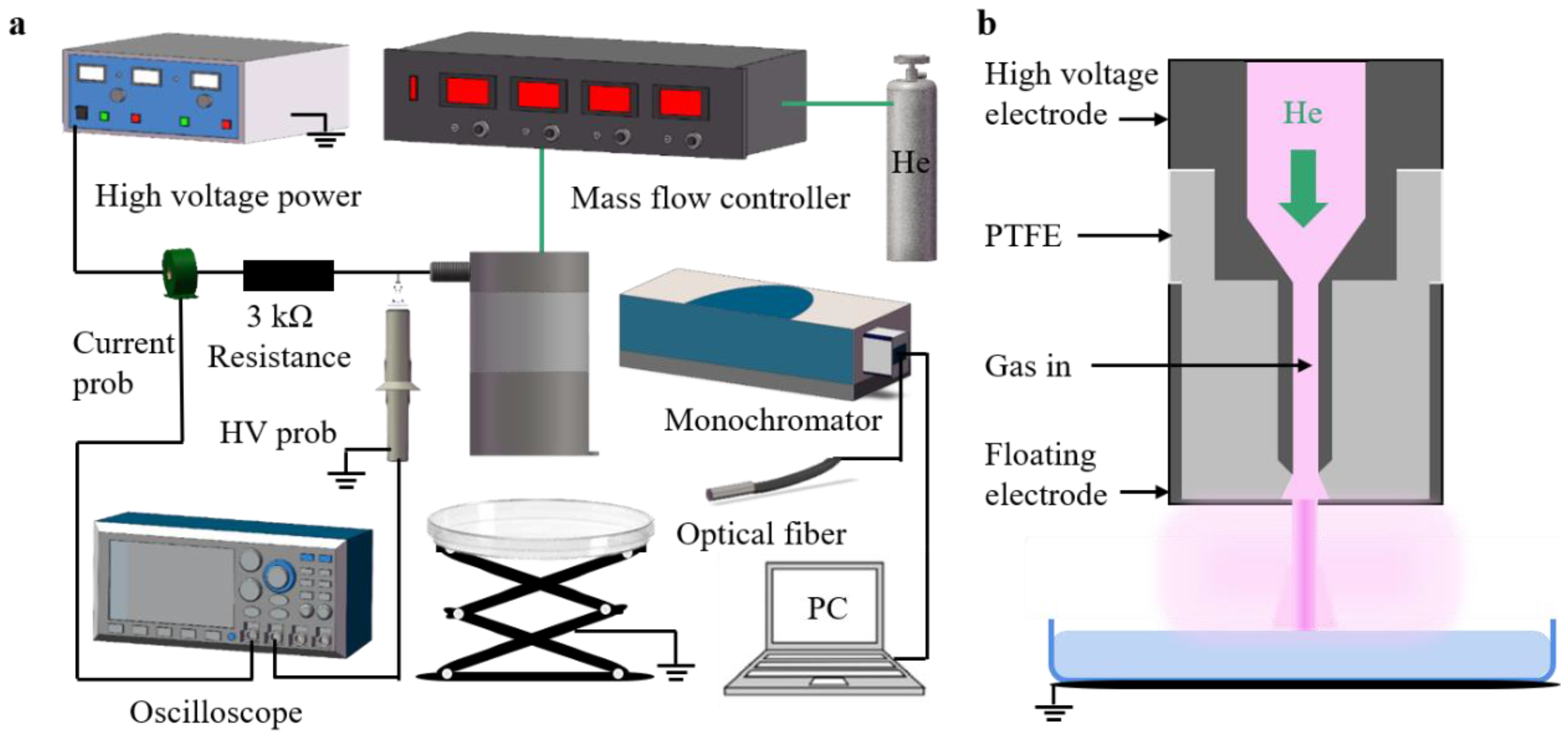
2. Experiment Setup
3. Result and Discussion
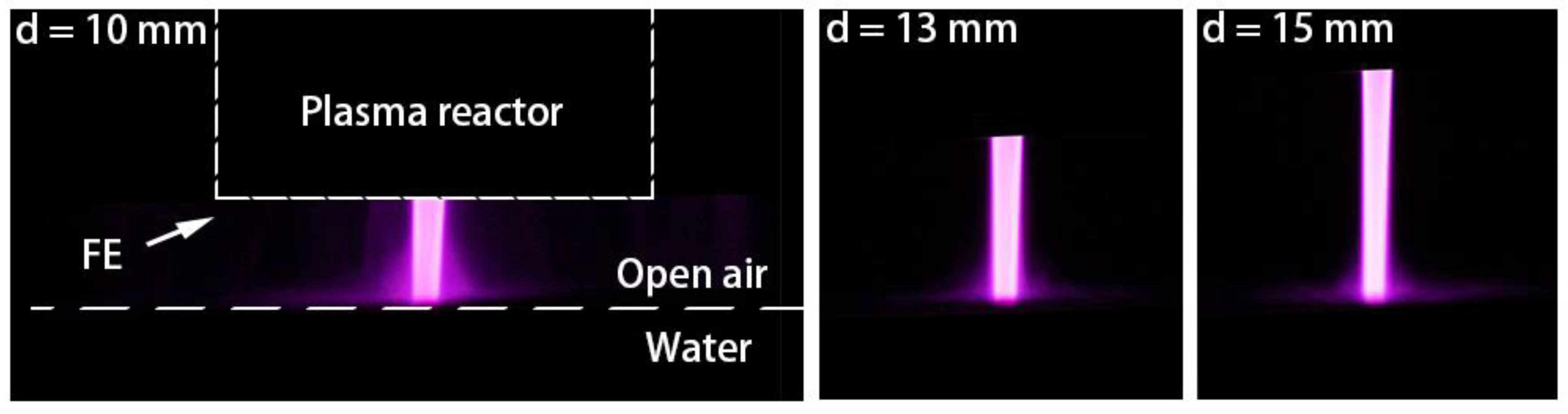
3.1. Visualization Characteristics of FEGLD Plasma
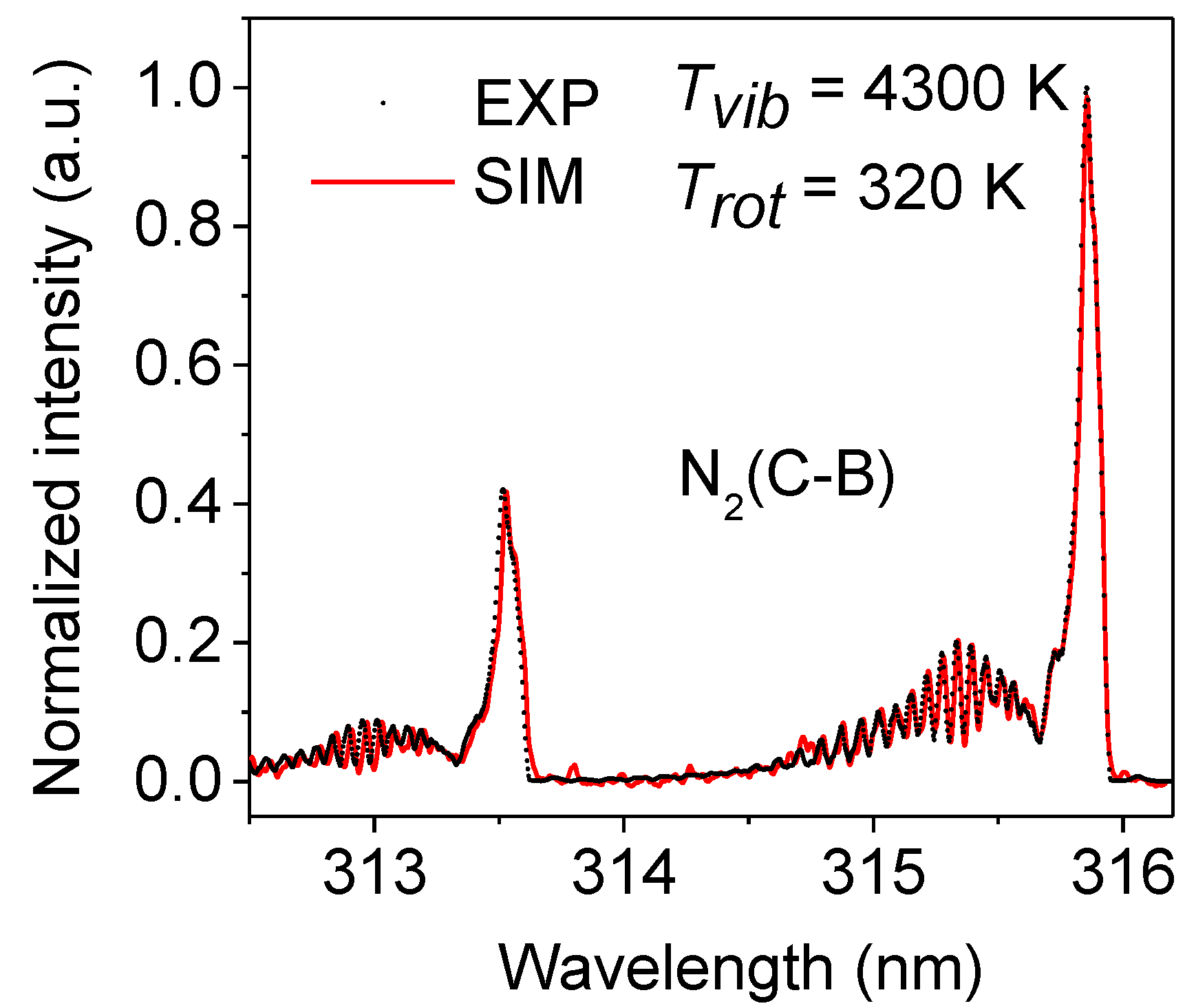
3.2. Spectral Characteristics of FEGLD
3.3. Electrical Characteristics of FEGLD
3.4. Gas Temperature of FEGLD
3.5. Electron Density of FEGLD
3.6. Spatial Distributions Characteristic of the FEGLD
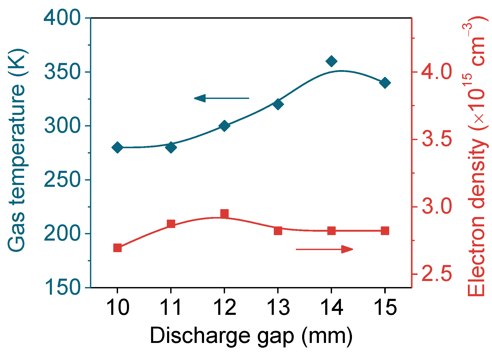
3.7. The Effects of Discharge Gap on FEGLD
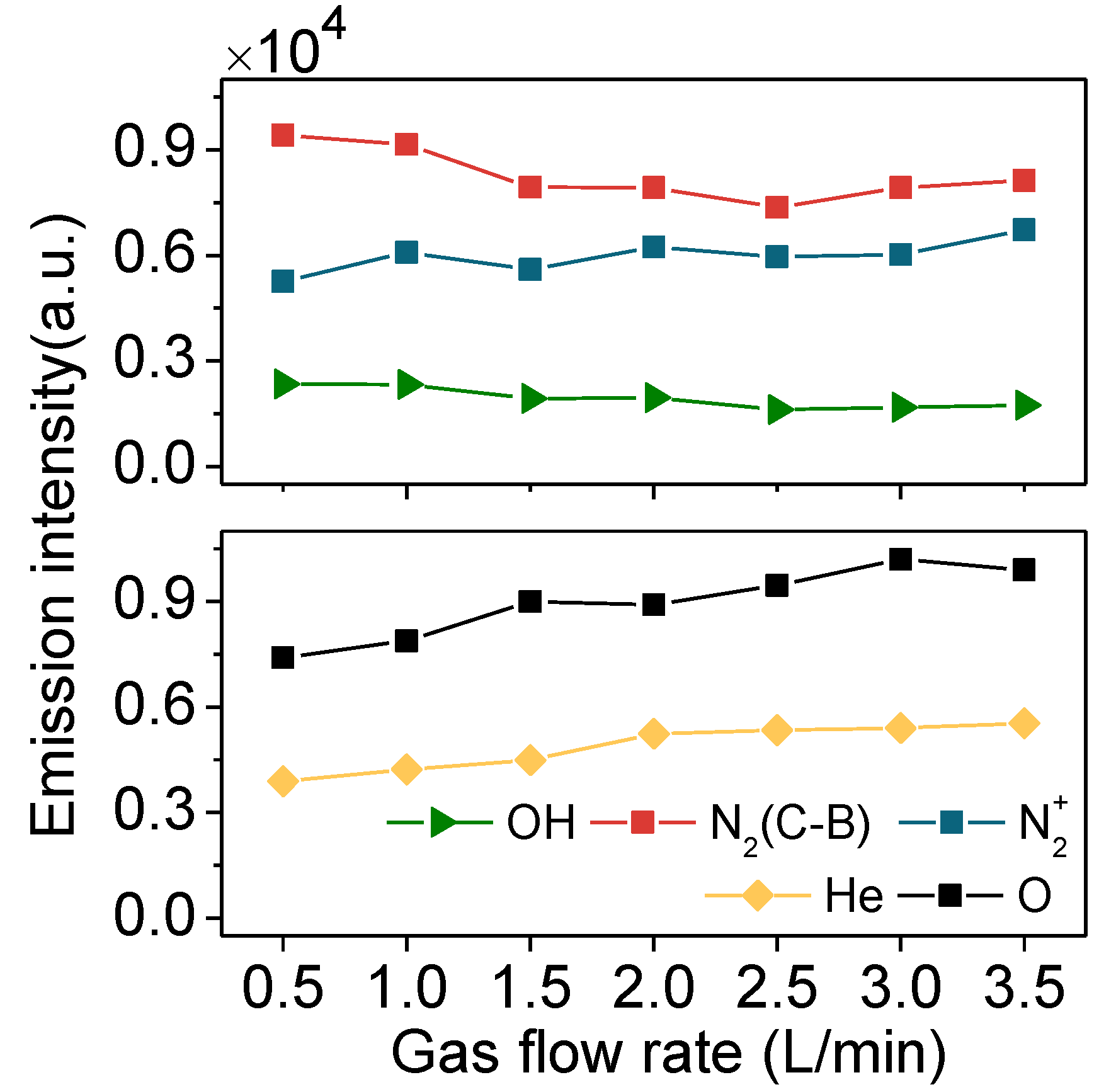
3.8. The Effects of the Helium Flow Rate on FEGLD
4. Conclusions
Author Contributions
Funding
Conflicts of Interest
References
- El Shaer, M.; Eldaly, M.; Heikal, G. Antibiotics Degradation and Bacteria Inactivation in Water by Cold Atmospheric Plasma Discharges Above and Below Water Surface. Plasma Chem. Plasma Process. 2020, 40, 971–983. [Google Scholar] [CrossRef]
- Gururani, P.; Bhatnagar, P.; Bisht, B. Cold plasma technology: Advanced and sustainable approach for wastewater treatment. Environ. Sci. Pollut. Res. Int. 2021, 28, 65062–65082. [Google Scholar] [CrossRef] [PubMed]
- Yang, D.Z.; Zhou, X.F.; Liang, J.P. Degradation of methylene blue in liquid using high-voltage pulsed discharge plasma synergizing iron-based catalyst-activated persulfate. J. Phys. D Appl. Phys. 2021, 54, 244002. [Google Scholar] [CrossRef]
- Laroussi, M.; Bekeschus, S.; Keidar, M. Low-Temperature Plasma for Biology, Hygiene, and Medicine: Perspective and Roadmap. IEEE Trans. Radiat. Plasma Med. Sci. 2022, 6, 127–157. [Google Scholar] [CrossRef]
- Qin, H.; Qiu, H.; He, S.T. Efficient disinfection of SARS-CoV-2-like coronavirus, pseudotyped SARS-CoV-2 and other coronaviruses using cold plasma induces spike protein damage. J. Hazard. Mater. 2022, 430, 128414. [Google Scholar] [CrossRef] [PubMed]
- Busco, G.; Robert, E.; Chettouh-Hammas, N. The emerging potential of cold atmospheric plasma in skin biology. Free Radic. Biol. Med. 2020, 161, 290–304. [Google Scholar] [CrossRef]
- Lu, Q.F.; Li, J.L.; Yu, J. Preparation of Ta2O5 nanoparticles by using cathode glow discharge electrolysis. Mater. Res. Express. 2021, 8, 125011. [Google Scholar] [CrossRef]
- Sirotkin, N.A.; Khlyustova, A.V.; Titov, V.A. The Use of a Novel Three-Electrode Impulse Underwater Discharge for the Synthesis of W-Mo Mixed Oxide Nanocomposites. Plasma Chem. Plasma Process. 2021, 42, 191–209. [Google Scholar] [CrossRef]
- Wang, H.; Xu, Q.; Zhou, X. Highly efficient adsorptive removal of persistent organic pollutants using NPD-acid combined modified NaY zeolites. Chem. Eng. J. 2022, 431, 133858. [Google Scholar] [CrossRef]
- Liu, W.; Bao, Y.; Duan, X. Study on water treatment effect of dispersion discharge plasma based on flowing water film electrode. Plasma Sci. Technol. 2021, 23, 105502. [Google Scholar] [CrossRef]
- Zhou, R.; Liu, B.; Li, Y. Reduced breakdown voltage for in-liquid plasma discharges using moveable electrodes. J. Phys. D Appl. Phys. 2021, 55, 10LT01. [Google Scholar] [CrossRef]
- Liang, J.; Zhou, X.; Zhao, Z. Discharge characteristics and reactive species production of unipolar and bipolar nanosecond pulsed gas–liquid discharge generated in atmospheric N2. Plasma Sci. Technol. 2021, 23, 095405. [Google Scholar] [CrossRef]
- Szulc, M.; Forster, G.; Marques-Lopez, J.L. Influence of Pulse Amplitude and Frequency on Plasma Properties of a Pulsed Low-Current High-Voltage Discharge Operated at Atmospheric Pressure. Appl. Sci. 2022, 12, 6580. [Google Scholar] [CrossRef]
- Liang, J.; Zhou, X.; Zhao, Z. Reactive oxygen and nitrogen species in Ar + N2 + O2 atmospheric-pressure nanosecond pulsed plasmas in contact with liquid. Phys. Plasmas 2019, 26, 023521. [Google Scholar] [CrossRef]
- Korolev, Y.D.; Frants, O.B.; Landl, N.V. Features of a near-cathode region in a gliding arc discharge in air flow. Plasma Sources Sci. Technol. 2014, 23, 54016. [Google Scholar] [CrossRef]
- Baeva, M.; Loffhagen, D.; Becker, M.M. Fluid Modelling of DC Argon Microplasmas: Effects of the Electron Transport Description. Plasma Chem. Plasma Process. 2019, 39, 949–968. [Google Scholar] [CrossRef]
- Rousso, A.C.; Goldberg, B.M.; Chen, T.Y. Time and space resolved diagnostics for plasma thermal-chemical instability of fuel oxidation in nanosecond plasma discharges. Plasma Sources Sci. Technol. 2020, 29, 105012. [Google Scholar] [CrossRef]
- Saifutdinov, A.I. Unified simulation of different modes in atmospheric pressure DC discharges in nitrogen. J. Appl. Phys. 2021, 129, 093302. [Google Scholar] [CrossRef]
- Bruggeman, P.J.; Iza, F.; Brandenburg, R. Foundations of atmospheric pressure non-equilibrium plasmas. Plasma Sources Sci. Technol. 2017, 26, 123002. [Google Scholar] [CrossRef]
- Bruggeman, P.J.; Frontiera, R.R.; Kortshagen, U.R. Plasma-driven solution electrolysis. J. Appl. Phys. 2021, 129, 200902. [Google Scholar] [CrossRef]
- Yang, D.Z.; Jia, L.; Wang, W.C. Atmospheric Pressure Gas-Liquid Diffuse Nanosecond Pulse Discharge Used for Sterilization in Sewage. Plasma Process Polym. 2014, 11, 842–849. [Google Scholar] [CrossRef]
- Yuan, H.; Yang, D.; Jia, Z. Activated Carbon Modified by Nanosecond Pulsed Discharge for Polycyclic Aromatic Hydrocarbons Detection. Plasma Chem. Plasma Process. 2020, 40, 1539–1553. [Google Scholar] [CrossRef]
- Herrmann, A.; Margot, J.; Hamdan, A. Influence of voltage and gap distance on the dynamics of the ionization front, plasma dots, produced by nanosecond pulsed discharges at water surface. Plasma Sources Sci. Technol. 2022, 31, 045006. [Google Scholar] [CrossRef]
- Gromov, M.; Leonova, K.; Britun, N. Plasma nitrogen fixation in the presence of a liquid interface: Role of OH radicals. React. Chem. Eng. 2022, 7, 1047–1052. [Google Scholar] [CrossRef]
- Xu, H.; Liu, D.; Xia, W. Comparison between the water activation effects by pulsed and sinusoidal helium plasma jets. Phys. Plasmas 2018, 25, 013520. [Google Scholar] [CrossRef]
- Wang, S.; Yang, D.; Liu, F. Spectroscopic study of bipolar nanosecond pulse gas-liquid discharge in atmospheric argon. Plasma Sci. Technol. 2018, 20, 075404. [Google Scholar] [CrossRef]
- Wang, S.; Yang, D.Z.; Zhou, R. Mode transition and plasma characteristics of nanosecond pulse gas–liquid discharge: Effect of grounding configuration. Plasma Process Polym. 2019, 17, 1900146. [Google Scholar] [CrossRef]
- Divya Deepak, G. Review on recent advances in cold plasma technology. Eur. Phys. J. Appl. Phys. 2022, 97, 39. [Google Scholar] [CrossRef]
- Zhu, T.; Liu, J.; Xin, Y. Hydrogen production by microwave discharge in liquid: Study on the characteristics effect of suspended electrode. J. Anal. Appl. Pyrolysis 2022, 164, 164. [Google Scholar] [CrossRef]
- Hu, W.; Wang, J.; Xu, W. Electrical and Optical Characteristics of a Color Alternating Current Plasma Display Panel With Floating Electrodes. J. Disp. Technol. 2013, 9, 100–105. [Google Scholar] [CrossRef]
- Lee, H.W.; Nam, S.H.; Mohamed, A.-A.H. Atmospheric Pressure Plasma Jet Composed of Three Electrodes: Application to Tooth Bleaching. Plasma Process Polym. 2010, 7, 274–280. [Google Scholar] [CrossRef]
- Liu, W.; Ma, C.; Li, Z. Generation of atmospheric-pressure homogeneous dielectric barrier discharge in air. EPL Europhys. Lett. 2017, 118, 45001. [Google Scholar] [CrossRef]
- Liu, Z.J.; Wang, W.C.; Zhang, S. Optical study of a diffuse bipolar nanosecond pulsed dielectric barrier discharge with different dielectric thicknesses in air. Eur. Phys. J. D 2012, 66, 319. [Google Scholar] [CrossRef]
- Eichwal, O. Coupling of chemical kinetics, gas dynamics, and charged particle kinetics models for the analysis of NO reduction from flue gases. J. Appl. Phycol. 1997, 82, 4781–4794. [Google Scholar] [CrossRef]
- Yang, D.; Wang, W.; Wang, K. Spatially resolved spectra of excited particles in homogeneous dielectric barrier discharge in helium at atmospheric pressure. Spectrochim. Acta A 2010, 76, 224–229. [Google Scholar] [CrossRef]
- Niemi, K.; Waskoenig, J.; Sadeghi, N. The role of helium metastable states in radio-frequency driven helium–oxygen atmospheric pressure plasma jets: Measurement and numerical simulation. Plasma Sources Sci. Technol. 2011, 20, 055005. [Google Scholar] [CrossRef]
- Liu, Y.; Liu, D.; Zhang, J. 1D fluid model of RF-excited cold atmospheric plasmas in helium with air gas impurities. Phys. Plasmas 2020, 27, 043512. [Google Scholar] [CrossRef]
- Kovačević, V.V.; Dojčinović, B.P.; Jović, M. Measurement of reactive species generated by dielectric barrier discharge in direct contact with water in different atmospheres. J. Phys. D Appl. Phys. 2017, 50, 155205. [Google Scholar] [CrossRef]
- Lai, J.; Foster, J.E. Time-resolved imaging of streamer formation inside gaseous bubbles in liquids. J. Phys. D Appl. Phys. 2020, 53, 025206. [Google Scholar] [CrossRef]
- Luo, S.; Denning, C.M.; Scharer, J.E. Laser-rf creation and diagnostics of seeded atmospheric pressure air and nitrogen plasmas. J. Appl. Phys. 2008, 104, 013301. [Google Scholar] [CrossRef] [Green Version]
- Bruggeman, P.J.; Sadeghi, N.; Schram, D.C. Gas temperature determination from rotational lines in non-equilibrium plasmas: A review. Plasma Sources Sci. Technol. 2014, 23, 023001. [Google Scholar] [CrossRef]
- Zhang, L.; Yang, D.; Wang, W. Needle-array to Plate DBD Plasma Using Sine AC and Nanosecond Pulse Excitations for Purpose of Improving Indoor Air Quality. Sci. Rep. 2016, 6, 25242. [Google Scholar] [CrossRef] [PubMed]
- Wang, Q.; Koleva, I.; Donnelly, V.M. Spatially resolved diagnostics of an atmospheric pressure direct current helium microplasma. J. Phys. D Appl. Phys. 2005, 38, 1690–1697. [Google Scholar] [CrossRef]
- Laux, C.O. Optical diagnostics of atmospheric pressure air plasmas. Plasma Sources Sci. Technol. 2003, 12, 125–138. [Google Scholar] [CrossRef]
- Nikiforov, A.Y.; Leys, C.; Gonzalez, M.A. Electron density measurement in atmospheric pressure plasma jets: Stark broadening of hydrogenated and non-hydrogenated lines. Plasma Sources Sci. Technol. 2015, 24, 015015. [Google Scholar] [CrossRef]
- Gigosos, M.A.; González, M.Á.; Cardeñoso, V.n. Computer simulated Balmer-alpha, -beta and -gamma Stark line profiles for non-equilibrium plasmas diagnostics. Sci. Rep. 2003, 58, 1489–1504. [Google Scholar] [CrossRef]
- Djurović, S.; Konjević, N. On the use of non-hydrogenic spectral lines for low electron density and high pressure plasma diagnostics. Plasma Sources Sci. Technol. 2009, 18, 035011. [Google Scholar] [CrossRef]
- Qian, M.; Ren, C.; Wang, D. Stark broadening measurement of the electron density in an atmospheric pressure argon plasma jet with double-power electrodes. J. Appl. Phys. 2010, 107, 063303. [Google Scholar] [CrossRef]
- Adams, N.G.; Bhatia, A.K.; Amusia, M.Y.; Louck, D.J.; Jud, R.B.; Paldus, J.; Hill, N.R.; Gallagher, A.; Fischer, F.C.; Grant, P.I.; et al. Springer Hand Book of Atomic Molecular, and Optical Physics; Drake, G.W.F., Ed.; Drake Springer Science+Business Media, Inc.: New York, NY, USA, 2006; ISBN 978-3-030-73892-1. [Google Scholar]
- Cox, A.N.; Däppen, W.; Cowley, C.; Wiese, L.W.; Fuhr, J.; Kuznetsova, A.L.; Keady, J.J.; Kilcrease, D.P.; Hjellming, M.R.; Tokunaga, A.T.; et al. Allen Astrophysical Quantities; Springer: New York, NY, USA, 1999; ISBN 978-1-4612-1186-0. [Google Scholar]
- Hofmann, S.; van Gessel, A.F.H.; Verreycken, T. Power dissipation, gas temperatures and electron densities of cold atmospheric pressure helium and argon RF plasma jets. Plasma Sources Sci. Technol. 2011, 20, 065. [Google Scholar] [CrossRef]
- Sretenovic, G.B.; Krstic, I.B.; Kovacevic, V.V. Spectroscopic Study of Low-Frequency Helium DBD Plasma Jet. IEEE Trans. Plasma Sci. 2012, 40, 2870–2878. [Google Scholar] [CrossRef]
- Kovačević, V.V.; Sretenović, G.B.; Slikboer, E. The effect of liquid target on a nonthermal plasma jet—imaging, electric fields visualization of gas flow and optical emission spectroscopy. J. Phys. D Appl. Phys. 2018, 51, 065202. [Google Scholar] [CrossRef]
- Bruggeman, P.; Iza, F.; Guns, P. Electronic quenching of OH(A) by water in atmospheric pressure plasmas and its influence on the gas temperature determination by OH(A–X) emission. Plasma Sources Sci. Technol. 2010, 19, 015016. [Google Scholar] [CrossRef]
- Verreycken, T.; van Gessel, A.F.H.; Pageau, A. Validation of gas temperature measurements by OES in an atmospheric air glow discharge with water electrode using Rayleigh scattering. Plasma Sources Sci. Technol. 2011, 20, 024002. [Google Scholar] [CrossRef]
- Ono, R.; Teramoto, Y.; Oda, T. Effect of humidity on gas temperature in the afterglow of pulsed positive corona discharge. Plasma Sources Sci. Technol. 2010, 19, 015009. [Google Scholar] [CrossRef]
- Tendero, C.; Tixier, C.; Tristant, P. Atmospheric pressure plasmas: A review. Sci. Rep. 2006, 61, 2–30. [Google Scholar] [CrossRef]
- Fridman, G.; Peddinghaus, M.; Balasubramanian, M. Blood Coagulation and Living Tissue Sterilization by Floating-Electrode Dielectric Barrier Discharge in Air. Plasma Chem. Plasma Process. 2006, 26, 425–442. [Google Scholar] [CrossRef]
- Walsh, J.L.; Iza, F.; Janson, N.B. Three distinct modes in a cold atmospheric pressure plasma jet. J. Phys. D Appl. Phys. 2010, 43, 075201. [Google Scholar] [CrossRef]
- Lepikhin, N.D.; Luggenhölscher, D.; Czarnetzki, U. Electric field measurements in a He:N2 nanosecond pulsed discharge with sub-ns time resolution. J. Phys. D Appl. Phys. 2021, 54, 055201. [Google Scholar] [CrossRef]
- Wang, S.; Wang, W.C.; Yang, D.Z. Optical and application study of gas-liquid discharge excited by bipolar nanosecond pulse in atmospheric air. Spectrochim. Acta A 2014, 131, 571–576. [Google Scholar] [CrossRef] [PubMed]
- Yue, Y.; Pei, X.; Gidon, D. Investigation of plasma dynamics and spatially varying O and OH concentrations in atmospheric pressure plasma jets impinging on glass, water and metal substrates. Plasma Sources Sci. Technol. 2018, 27, 064001. [Google Scholar] [CrossRef]
- Iseki, S.; Ohta, T.; Aomatsu, A. Rapid inactivation of Penicillium digitatum spores using high-density nonequilibrium atmospheric pressure plasma. Appl. Phys. Lett. 2010, 96, 153704. [Google Scholar] [CrossRef] [PubMed] [Green Version]


| NO. | Reaction | Rate Constant | Ref. |
|---|---|---|---|
| 1 | 7.0 × 10⁻¹¹ cm3 s−1 | [35] | |
| 2 | 2.6 × 10⁻¹⁶ cm3 s−1 | [36] | |
| 3 | 1.5 × 10⁻¹⁰ cm3 s−1 | [37] | |
| 4 | 1.1 × 10⁻¹⁰ cm3 s−1 | [33] | |
| 5 | 8.0 × 10⁻¹¹ cm3 s−1 | [33] | |
| 6 | 2.4 × 10⁻¹² cm3 s−1 | [34] | |
| 7 | 3.2 × 10⁻¹¹ cm3 s−1 | [34] | |
| 8 | 2.6 × 10⁻¹² cm3 s−1 | [34] | |
| 9 | —— | [38] |
| Broadening Effect | Value (nm) |
|---|---|
| Doppler broadening | 0.008 |
| Instrument broadening | 0.078 |
| Van der Waals broadening | 0.044 |
| Natural broadening | 10−5 |
| Stark broadening | 0.156 |
Publisher’s Note: MDPI stays neutral with regard to jurisdictional claims in published maps and institutional affiliations. |
© 2022 by the authors. Licensee MDPI, Basel, Switzerland. This article is an open access article distributed under the terms and conditions of the Creative Commons Attribution (CC BY) license (https://creativecommons.org/licenses/by/4.0/).
Share and Cite
Li, S.; Liu, Y.; Yuan, H.; Liang, J.; Zhang, M.; Li, Y.; Yang, D. Generation of High-Density Pulsed Gas–Liquid Discharge Plasma Using Floating Electrode Configuration at Atmospheric Pressure. Appl. Sci. 2022, 12, 8895. https://doi.org/10.3390/app12178895
Li S, Liu Y, Yuan H, Liang J, Zhang M, Li Y, Yang D. Generation of High-Density Pulsed Gas–Liquid Discharge Plasma Using Floating Electrode Configuration at Atmospheric Pressure. Applied Sciences. 2022; 12(17):8895. https://doi.org/10.3390/app12178895
Chicago/Turabian StyleLi, Shuqi, Yunhu Liu, Hao Yuan, Jianping Liang, Min Zhang, Yao Li, and Dezheng Yang. 2022. "Generation of High-Density Pulsed Gas–Liquid Discharge Plasma Using Floating Electrode Configuration at Atmospheric Pressure" Applied Sciences 12, no. 17: 8895. https://doi.org/10.3390/app12178895
APA StyleLi, S., Liu, Y., Yuan, H., Liang, J., Zhang, M., Li, Y., & Yang, D. (2022). Generation of High-Density Pulsed Gas–Liquid Discharge Plasma Using Floating Electrode Configuration at Atmospheric Pressure. Applied Sciences, 12(17), 8895. https://doi.org/10.3390/app12178895