Abstract
High clearance sprayer is a high-efficiency pesticide application machine in orchard management. In this paper, operational safety of high clearance sprayers is validated by using finite element simulation and vibration testing. The 3D model of the frame is simplified by using shell units instead of solid units, the static performance of high clearance sprayer frames under static full load and ultimate torsional conditions was studied by means of finite element simulation tests, the mechanical properties of the frame under step excitation were studied by multi-body dynamic simulation test. The simulation results show that, at a safety factor of 1.5, the maximum stress extremes in the frame are within the safe permissible stress range. During the dynamics analysis, a tire-ground contact simplified model was proposed. The results of the modal analysis show that the inherent frequency distribution of the high clearance sprayer is compact, and the vibration test has measured a large difference between the engine vibration frequency with the inherent frequency of the frame, this means that resonance will not occur. The theoretical analysis shows that the designed high clearance sprayer meets the requirements of large cross-row field operations, the study provides a reference for the overall design of the high clearance sprayer.
1. Introduction
Due to the fact that large-scale high clearance sprayers can solve the problem of difficult drug delivery and poor control effect of high stalk crops in the middle and late growth period [1,2,3]. As a high-efficiency plant protection operation machine, the high clearance sprayer is favored by relevant plant protection operators because of its fast operation speed, high pest control efficiency, and not ease to damage crops [4,5,6]. As the high clearance sprayer chassis frame carries heavy equipment such as water tanks (full load) and engines, the load impact when subjected to road excitation has a significant impact on the sprayer chassis frame [7,8]. A safety analysis of the sprayer chassis frame is essential [9,10].
The high clearance sprayer provides a multifunctional application platform for plant protection operations, meeting the application requirements of different sizes of plots and the standard of uniform application [11,12]. Based on the Newmark-β method, Xing M et al. proposed a numerical simulation method for solving the differential equations to study the effect of the man-machine seat of a high clearance sprayer machine under load excitation [13]. A finite element model of the high clearance sprayer was established, Yu Chen et al. analyzed and tested that the overall strength and stiffness of the chassis frame of the high clearance sprayer met the requirements [14].
The spray boom system of sprayers is increasingly being investigated, as the effects of ground excitation on sprayers can be evident in the vibration behavior of the spray boom [15,16]. Cui et al. established a system of higher-order differential equations to describe the kinematic behavior of the spray bar using kinetic equations, the dynamic characteristics of the passive suspension are investigated, and the effects of factors such as damping, friction, and pendulum length on the response characteristics are analyzed [17]. Chen W et al. use ultrasonic sensors to measure the height difference between the two ends of the spray bar and use the measurements to calculate the required spray bar tilt angle for control, using the control system to keep the bar in the desired position [18].
The optimization and improvement of various vehicle components through digital prototype analysis have been widely used. A finite element model of the frame of an agricultural vehicle was carried out in virtual model simulation, Kong S L, and provided a basis for subsequent optimization of the frame structure based on the simulation results [19]. A finite element model of the tipper frame was established and carried out simulation analysis of its static and dynamic performance by Ren Y, obtain the variation of the amplitude and deflection of the tipper frame and the stress distribution state of the frame, provide a reference for the subsequent improvement of the frame [20].
With innovations in measurement methods, there are various ways of testing the properties of metallic materials. Digital image correlation system (DIC) combined with related technology can be used to observe the stress concentration area of metal materials and predict the location of the failure area [21,22]. The use of 3D laser Doppler vibration measurement systems for non-contact inspection of materials is an advanced technological tool. The technique allows measurements to be made without touching the object and can be used for modal analysis of objects and surface quality inspection [23,24]. For large frame vibration tests, triaxial acceleration sensors are now mostly used. The amplitude and frequency of the frame vibrations are measured in the vibration test to assess the safety of the vehicle [25].
As a highly efficient plant protection machine, the large cross-row sprayer is often used for spraying high stalk crops. High clearance sprayers designed for use in grape orchards to improve the efficiency of orchard operations. To ensure the operational safety of sprayers, in this paper, the mechanical properties on high clearance sprayers are investigated by means of finite element simulation and vibration tests. This paper uses shell cells in place of solid cells to simplify the 3D model of the sprayer frame. The static full load and extreme torsion conditions of the sprayer were studied by finite element simulation and the simulation results were analyzed. During the dynamics simulation, the forces on the sprayer under step excitation are investigated and a simplified model is proposed to replace the tire-ground contact [26,27]. The simplified model can significantly reduce the amount of calculations with the correct results. The vibration law of the sprayer was studied by carrying out modal analysis and vibration tests.
2. Materials and Methods
2.1. Machines and Modeling
The large across-rows orchard sprayer was designed to improve the efficiency of grape orchard operations. In this paper, the safety of the sprayer was tested by finite element simulation test and vibration test. The large-scale orchard sprayer is mainly composed of a frame, spray boom, engine, cab and spray system, as shown in Figure 1. The machine size is 4600 × 2600 × 3000 mm, the wheelbase is 2200–3400 mm, the water tank on the left and right of the frame has a capacity of 600 L and the clearance from the ground is more than 2200 mm. The orchard sprayer adopts liftable cab, engine in the middle, spray rod in the rear, medicine box installed on both sides of the frame. The sprayer adopts 100 horsepower engine, mechanical four-wheel drive, equipped with hydraulic four wheels steering system, reducing the turning radius. The orchard sprayer adopts a gantry frame and can adjust wheelbase freely through hydraulic cylinder.
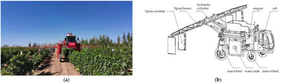
Figure 1.
High Clearance Sprayer solid diagram and mapped 3D diagram. (a) is the high clearance spray machine prototype; (b) is the high clearance spray machine model.
Due to the large number of components and complex structure of the sprayer frame, it is necessary to simplify the imported model. In order to reduce the computational effort, the model is processed by extracting mid-surface and converting solid units to face units.
The frame of a sprayer machine is an assembly composed of parts connected to each other, and there are mutual motion relationships between the parts, and the mutual motion relationship between the parts has a very important influence on the results of stress and strain. Therefore, when building the finite element model of the sprayer frame, it is necessary to consider the relative motion relationship existing between the parts of the frame assembly. The main structure of the frame is mainly connected by welding, and the contact method between each member is set to bond, and the parts with rotating relation are set to revolute, and the friction coefficient is set to 0.02.
The mechanical movement of the whole sprayer frame is mainly controlled by the hydraulic boom. However, in the process of sprayer movement, the hydraulic boom is in the locked state and there is no relative movement at both ends of the hydraulic boom. Therefore, the hydraulic boom in the frame is simplified to a large stiffness spring of 20,000 N/mm.
The material of the frame studied in this paper is Q345 structural steel, and the specific parameters are shown in Table 1.

Table 1.
Material properties of Q345.
The frame of the sprayer belongs to a thin-wall structure. That is, the characteristic size thickness, and length differ greatly. The main analysis parts of the frame were extracted and the solid element was converted into the shell element. The final simplified finite element model of the sprayer frame is shown in Figure 2.
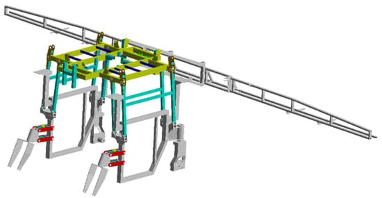
Figure 2.
The color structure in the Figure is the part where the shell element is used in the simulation analysis of the sprayer.
As the bearing structure of the sprayer, the main parts of the sprayer are installed on the frame. The sprayer in the operation of the driving process of the working conditions is mainly full load bending, extreme twisting two.
The load of the sprayer frame mainly includes the weight of the cab, the weight of the power system, the weight of the front and rear axles, the weight of the diesel tank, the weight of the hydraulic tank, the weight of the liquid tank (full liquid), etc. The details of the individual parts of the chassis are shown in Table 2.
Table 2.
Quality parameters of component.
2.2. Static Simulation Test Design
2.2.1. Full Load Bending Condition
When the sprayer is operating at a uniform speed, all four wheels are in contact with the ground, and the load on the frame comes mainly from the weight of the various parts mounted on the frame and the spray equipment. In order to ensure the safety of the frame and the authenticity of the simulation, the frame load should be multiplied by a safety load factor (the safety load factor is 1.5 times in this paper). The boundary condition constrains all the degrees of freedom at the four wheels connections.
2.2.2. Ultimate Torsional Condition
The ultimate torsional condition of the frame is mainly considered when one wheel is hanging, and the rest of the wheels are on the ground. The boundary condition is that releases all degrees of freedom of the right front wheel and restricts all degrees of freedom of other wheels.
2.3. Modal Simulation Test Design
Modal analysis plays an important role in the study of the vibration performance of structures; when a vehicle is driven on the road, it vibrates due to internal and external excitations. When the sprayer frame is excited by the same frequency as the inherent frequency of the frame itself, the frame will resonate, causing the driver to feel strong vibration and discomfort, and the frame will also lead to damage and failure due to resonance. It is important to analyze the dynamic characteristics of the sprayer frame.
In order to be closer to the actual working conditions of the sprayer operation and to reflect the dynamic characteristics of the sprayer frame more realistically, the modal analysis of the sprayer frame was carried out using the restrained modal analysis with prestress.
2.4. Transient Simulation Test Design
When the sprayer passes through a raised obstacle on the ground, it is equivalent to a sudden increase in load on the frame. Since the frame itself carries a great load, the sudden increase in load from the ground will have a large impact on the sprayer frame, so it is necessary to study the state of the sprayer when it crosses the obstacle.
2.4.1. Simplification of the Tire Model
There are more types of automobile tires, the structural composition is complex, and the rubber is a super-elastomer; the model construction of the whole tire is more complex, which will greatly increase the computational volume of the simulation and easily lead to the inability to converge, so it is necessary to simplify the tire.
By reviewing the relevant literature found that the complex tire model can be transformed into an elastic-damping element, and the stiffness and damping magnitude of the simplified elastic-damping element is related to the tire pressure of the tire. The specific relationship is as follows [28].
Pressure–stiffness conversion equation:
Pressure–damping conversion equation:
As can be seen from Equations (1) and (2), when the tire pressure is greater than 140 MPa, the damping generated by the rubber deformation basically remains unchanged at 2 Ns/mm.
The tire pressure of the tire used in the high clearance sprayer is 350 KPa, which gives the equivalent stiffness of the tire damping element stiffness K = 517 N/mm and damping C = 2 N·S/mm.
2.4.2. The Setting of the Wheel Contact with the Ground
This would use a significant amount of computer resources if an actual model of the tire to ground contact of a high clearance sprayer was used. In order to reduce the amount of calculations and to ensure the accuracy of the results, a simplified model is created as in Figure 3. This simplified model can replace the actual contact between the tire and the ground, in the simplified model the tire was connected to the ground by using ‘Spring’ and ‘Damping’. Setting the ‘Spring’ in the model equal to the parameter K, ‘Damping’ is equal to the parameter C.
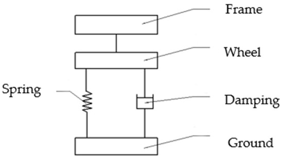
Figure 3.
Tire ground contact simplification.
The displacement excitation from the road is transferred through the simplified stiffness-damping element of the tire to the wheel hub and then to the frame. A finite element model of the sprayer with one side wheel over the barrier is shown in Figure 4.
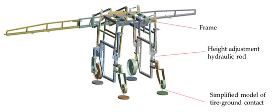
Figure 4.
Transient dynamics model for sprayers.
The four discs in Figure 4 simplify the ground and are used to load the excitation generated from ground obstacles connected to the hub by stiffness–damping elements.
2.4.3. Determination of the Basic Load
The environment is earth road when the sprayer works, and the obstacles are mainly gravel and bricks, so the wheels on one side of the sprayer are set to cross the obstacles with a rectangular cross-section of 50 mm × 30 mm. The displacement change time perpendicular to the ground directly in the process of the sprayer crossing the obstacle is extremely short; the displacement of the sprayer frame perpendicular to the ground direction can be regarded as a linear change to simplify the loading process of the load. The specific load carrying process is shown in Figure 5.
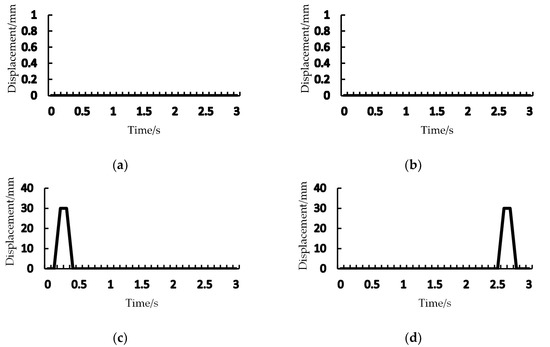
Figure 5.
Loading method for displacement loads on tires. (a) is a loading mode of the left front wheel; (b) is a loading mode of the left rear wheel; (c) is a loading mode of the right front wheel; (d) is a loading mode of the right rear wheel.
2.5. Vibration Test Design
In order to study the inherent vibration characteristics of the sprayer frame, and also to verify the accuracy of the modal analysis results, vibration tests were conducted on the frame, and the vibration response signals of the frame were collected under two operating conditions; namely, rated power revolution per minute (RPM) and idle speed of the engine, and the corresponding processing was carried out to analyze the response of the frame.
The Arrangement of Measurement Points
Due to the engine being placed in the chassis area, the engine excitation decreases with distance. Therefore, sensors were selected to be installed on the chassis where the engine is mounted for measurement. The measurement points were arranged at five different locations on the sprayer frame, and the positions of the five measurement points are shown in Figure 6. The measurement instrumentation installed on the high clearance sprayer consists of the host computer, a Donghua dynamic signal collector (DH5902) and a number of triaxial acceleration sensors (356A16), as shown in Figure 7. The sampling frequency of the vibration test should be greater than twice the frequency of the measured signal; therefore, the sampling frequency in the test is 1 kHz and the test sampling duration is 30 s [25]. The specifications of the equipment parameters used in the test are shown in Table 3.
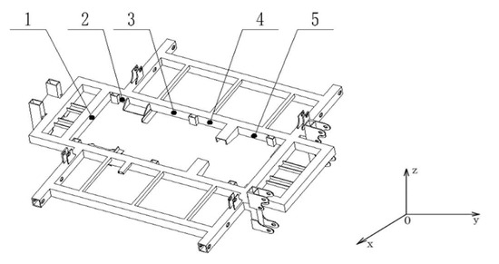
Figure 6.
Position on the frame for vibration testing. Points 1–5 are the positions of the five measurement points.
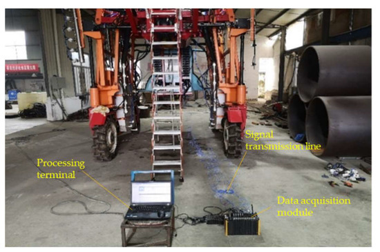
Figure 7.
Site view of the vibration test on the frame of the sprayer frame.
Table 3.
Performance parameters of vibration test instruments.
3. Results
3.1. Static Simulation Result
As can be seen in Figure 8, the overall stress in the sprayer frame under bending conditions is basically within 25 MPa, and the maximum stress is 214.31 MPa at the trunnion plate of the left support frame. This is because the hydraulic rod attached to the trunnion panels are responsible for front-wheel height adjustment and structural stability, and both ends carry part of the sprayer body weight. Another reason is the right-angle structure at the trunnion plate, where the stress concentration phenomenon occurs.
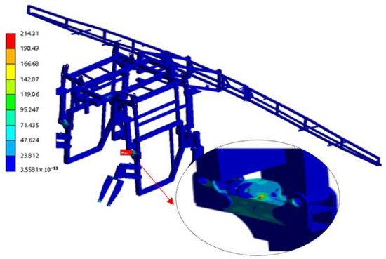
Figure 8.
Von Mises stresses diagram of the frame with full load bending condition.
In Figure 9, the overall stress of the frame is mostly below 70 MPa, and the maximum stress appears at the left support frame trunnion at 309 MPa. When a load was applied 1.5 times, the maximum stress extreme of the complete vehicle was still less than the safe allowable stress of the frame material (345 MPa) [14]. This indicates that the safety factor of the whole vehicle is greater than 1.5, which is in the safe range, and that the design of the whole vehicle has no strength defects. This is due to the right front wheel hanging in the position of the frame in the relative torsion, the load is concentrated in the left side of the stress concentration, and the maximum stress value is located in the left side of the front wheel hydraulic rod connection, where the hydraulic rod to carry a certain frame load. In addition, it can be seen that the simulation matches the actual situation.
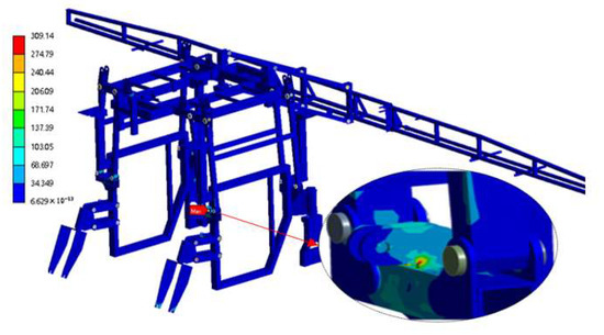
Figure 9.
Von Mises stresses diagram of the frame with extreme torsional condition.
3.2. Modal Simulation Result
The first 12 orders of inherent frequencies are shown in Table 4.
Table 4.
First 12 orders of inherent frequency.
3.3. Transient Dynamics Analysis of Sprayer Frame
A displacement load perpendicular to the ground was applied to the sprayer wheels, as shown in Figure 5, and transient dynamics analysis was performed. The obtained overall stresses of the sprayer frame as a function of time are shown in Figure 10.
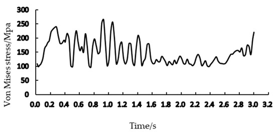
Figure 10.
Simulated stress result diagram for the sprayer frame.
From Figure 10, it can be seen that the maximum stress occurs at 0.93 s during the whole process of the sprayer frame crossing the barrier, and the stress distribution diagram for 0.93 s is extracted, as shown in Figure 11.
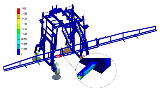
Figure 11.
Von Mises stresses the distribution diagram of the 0.93 s frame.
In Figure 11, it can be found that the maximum stress value is located in the middle spray boom and the connection of the single spray boom, the maximum stress value of 266.2 MPa. When a load of 1.5 times is applied, the stress extremes of the whole vehicle do not exceed the permissible stresses of the frame material and are within safe limits [14]. The main reason is the existence of gaps between the parts of the spray boom connection and the collision occurred in the process of the sprayer over the barrier, resulting in a large impact load. We can also find that most of the time, the stress of the sprayer frame in the process of crossing the barrier is below 250 MPa, the maximum stress is 266 MPa, the whole process of the spray frame is in a relatively safe state, and the design of the sprayer frame does not have serious problems.
The time variation of the maximum displacement of the sprayer frame throughout is shown in Figure 12.
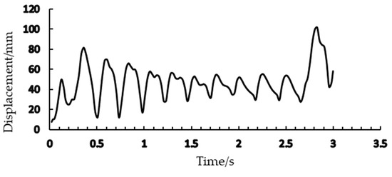
Figure 12.
Simulated displacement results for the sprayer frame.
The peak points in Figure 12 are extracted to generate a displacement deformation diagram. We can find that these peak points are all at the ends of the single spray boom; as can be seen in Figure 12, spray boom vibration at the beginning of the sprayer frame over the barrier, the spray boom reaches its maximum displacement deformation at the end of the front wheel over the barrier, after which the vibration starts to decay, and the displacement deformation of the spray boom gradually becomes smaller. When the rear wheels start to cross the barrier, the vibration of the spray boom starts to become larger, and the displacement deformation also starts to become larger, at which time the maximum displacement deformation occurs. Extract the displacement deformation at both ends of the spray boom, as shown in Figure 13 and Figure 14.
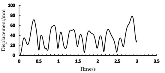
Figure 13.
Simulated displacement results of the left end of spray boom.
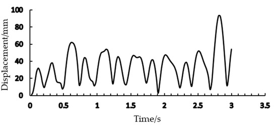
Figure 14.
Simulated displacement results of the right end of spray boom.
3.4. Vibration Test Results
The acceleration of the five measurement points under the excitation of engine idle speed and rated power speed was collected by the three-way acceleration sensor, and the time domain diagram of the acceleration of the five measurement points in X, Y, Z directions were obtained. In addition, the Fourier variation of the obtained time domain was performed to obtain the corresponding frequency domain diagram.
The first three peaks and corresponding frequencies of the five measurement points in the frequency spectrum are shown in Table 5 and Table 6.
Table 5.
Frequency data of measuring points in idle condition.
Table 6.
Frequency data of rated power revolution condition.
Due to many measurement points, the time domain and frequency domain diagram obtained from the analysis of measurement point 1 is used as an example (shown in Figure 15).
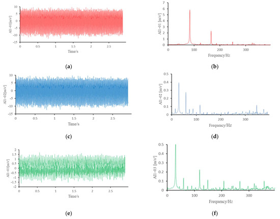
Figure 15.
Time and frequency domain diagram of measurement point 1 in X, Y and Z directions. (a) is time-domain diagram in the X direction; (b) is the frequency domain graph in the X direction; (c) is time-domain diagram in the Y direction; (d) is frequency-domain graph in the Y direction; (e) is time-domain diagram in the Z direction; (f) is frequency-domain graph in the Z direction.
By analyzing the time domain and frequency spectrum diagrams of point 1, we can see that the amplitude of the time domain curve changes less, and the curve distribution area is more concentrated, which means that the frame has no obvious defects and the overall frame stiffness is more suitable. The frequency spectrum diagram reveals that the frequencies around 30 Hz and 80 Hz are the main frequency components of frame vibration, which are in good agreement with the idle excitation frequency and rated RPM excitation frequency of the engine. It means that the vibration of the sprayer frame is mainly caused by the excitation of the engine, the vibration amplitude is small, and there is no obvious resonance phenomenon. It is shown that the engine excitation has a small effect on the frame, and its excitation frequency does not overlap with the intrinsic frequency of the frame, which does not cause a significant vibration response and verifies the correctness of the finite element model analysis.
4. Discussion
- 1.
- The effect of engine vibration frequency on the frame
The external excitation of the sprayer frame during operation comes mainly from the excitation of the frame by the unevenness of the road; The internal excitation comes mainly from the internal components of the sprayer during operation, such as the engine, fan, and diaphragm pump. The effect of engine operation on the spray frame is mainly considered in the modal analysis.
The rotational excitation frequency of the sprayer engine during operation is calculated by the following equation [29,30].
where n is the number of engine revolutions, r/min; z is the number of engine cylinders, and is the number of engine strokes. The engine used in the sprayer is 4G33TC four-cylinder from CHANGCHAI COMPANY, LIMITED, four-stroke inline water-cooled diesel engine with a rated working RPM of 2400 r/min and RPM for the unloaded operation of 900 r/min. Bringing in Equation (3), we can get the rotation excitation frequency of 4G33TC is 30 Hz at idle and 80 Hz at normal operation. According to Table 5 and Table 6, it can be seen that the main vibration frequencies of the sprayer are 30 Hz and 80 Hz, and this test result proves the accuracy of the calculation results.
The results in Table 5 show that in idle condition, the dominant vibration frequency at the test points is 30 Hz and the vibration amplitude is small. Test point 1 has a relatively even distribution of vibration amplitudes in the X, Y, and Z direction, while the remaining four test points have vibration amplitudes mainly in the X direction. This is because the engine is installed on the two beams in the Y direction, and the test point 1 is in the middle of the two supports. The excitation caused by the engine has little difference in the three directions, and the other four test points are all on the right side of the engine, so the vibration caused by the engine is shown in the X direction. This difference can be found in the same pattern in Table 6, and the reasons for this phenomenon are the same.
From Table 5 and Table 6, it can be seen that the inherent frequency of the sprayer frame gradually increases, but the value of the overall inherent frequency is small. It can be seen that the first 12th order inherent frequency of the sprayer frame ranges from 2.1 to 14.35 Hz, which does not overlap with the engine excitation frequency of 30 or 80 Hz and will not resonate with the engine excitation.
- 2.
- Effect of step excitation on spray bar deformation
From Figure 11 and Figure 12 it can be seen that the two ends of the spray boom make a reciprocal motion when the sprayer frame crosses the barrier, and there is a trend of vibration decay between the front and rear wheels crossing the barrier; there is also a lower peak between the two peak values in the Figure, which is due to the X, Y, and Z three directions in the simulation software and the displacement is calculated as follows.
As the displacement of the three directions is positive, there is no negative value, but there are positive and negative values of the displacement of a single direction, so between the other two higher crests appear to lower crests to the left end of the spray boom displacement deformation, for example, to extract the displacement of the left endpoint of the spray boom in three directions, the results are shown in Figure 13.
According to Figure 13 and Figure 14, it can be found that the displacement deformation of the spray bar is irregular motion, and the displacement deformation size is gradually decreasing [31]. From Figure 16, the displacement deformation of the spray bar in the X, Y and Z directions, the displacement deformation of the spray bar shows a cyclic reciprocal displacement when the sprayer is subjected to step excitation. The displacement transformation situation is based on the equilibrium position of the spray bar as the reference point, in each of the three directions of up and down movement, and cycle back and forth. Irregular movement occurs mainly due to the damping effect of the hydraulic rod itself installed on the spray bar, as well as the spray bar in the assembly process will appear gaps, these gaps lead to irregular collisions of the spray bar. The deformation of the spray bar is not consistent in the three directions of X, Y, and Z up and down movement because of the tendency of the material mechanics to rebound during deformation [17,32,33]. Taking the X-direction as an example, while the positive direction deformation is caused by the step excitation, the negative direction is caused by the rebound tendency of the material.
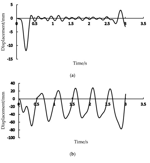
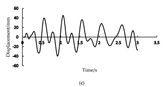
Figure 16.
Displacement results for the left endpoint of the spray boom. (a) is the X-direction displacement of the left endpoint; (b) is the Y-direction displacement of the left endpoint; (c) is the Z-direction displacement of the left endpoint.
The above analysis of the displacement deformation of the two ends of the spray boom and the left end in the X, Y and Z directions also confirms the above analysis of the reciprocating motion of the spray boom during the overrunning of the sprayer frame.
5. Conclusions
The high-clearance orchard sprayer work across-rows, which has the advantages of high efficiency and no harm to crops, making it the trend in plant protection machinery. In this paper, to ensure the operational safety of high clearance sprayers, the model is simplified by using shell cells instead of solid cells, and a simplified model of the tire-ground contact was proposed. The static and dynamic mechanical properties of high clearance sprayer frame were investigated by means of finite element simulation, and the static and dynamic simulation results were analyzed. Modal simulations were carried out to obtain the frame frequencies, and vibration tests were carried out to obtain the vibration law of the frame of the high clearance sprayer. The following conclusions are obtained:
- (1)
- Static simulation test results show that, when a load was applied 1.5 times, the maximum concentrated stress of the frame under static full load condition was 214.31 MPa, and the maximum concentrated stress of the frame under ultimate torsion condition was 309 MPa. The values are all less than the permissible stress of 345 MPa for the frame material, indicating that there are no strength defects in the whole vehicle.
- (2)
- The results of the dynamics simulation tests show that, under the combined effect of 1.5 times the load and step excitation, the maximum concentrated stress in the frame is 266.2 MPa, which is also less than the permissible stress in the frame material. The overall displacement variation of the spray bar shows a gradual decrease in peak value, which is consistent with the law of spray boom displacement variation under step excitation. This proves that the simplified model of tire and ground is correct. In the X, Y, and Z directions, the displacement pattern at the end of the spray bar is similar to that of a sine, but the peak of the displacement is gradually decreasing.
- (3)
- The modal simulation test results show that the inherent frequency of the whole vehicle is closely distributed (2.1–14.35 Hz), through the vibration test measurement to obtain the high clearance sprayer’s engine vibration frequency mainly at 30 Hz and 80 Hz, the whole machine inherent frequency and engine vibration frequency difference is large, which means that the sprayer will not occur resonance phenomenon.
According to the above conclusions, it is proven that the high clearance sprayer design meets the safety requirements. The variation law in displacement at the end of the spray bar will continue to be studied and which provide a reference for the attitude control of the spray boom. In addition, the stress concentration areas that appear in the finite element simulation results will be optimized, providing an optimization direction for the subsequent design of the high clearance sprayer.
Author Contributions
Conceptualization, H.C., S.D., M.O. and W.J.; methodology, H.C., S.D., S.L., C.W., Z.L., G.W. and Y.C.; software, H.C. and S.D.; validation, M.O. and W.J.; formal analysis, H.C. and S.D.; investigation, H.C. and S.D.; resources, M.O. and W.J.; data curation, H.C. and S.D.; writing—original draft preparation, H.C. and S.D.; writing—review and editing, H.C., S.D., M.O. and W.J.; project administration, M.O.; funding acquisition, W.J. All authors have read and agreed to the published version of the manuscript.
Funding
This work was funded by the Project of the Ningxia Hui Autonomous Region science and technology key R&D project (Grant No. 2018BBF02020).
Institutional Review Board Statement
Not applicable.
Informed Consent Statement
Not applicable.
Data Availability Statement
The data presented in this study are available on request from the corresponding author.
Acknowledgments
The author thanks Faculty of Agricultural Equipment of Jiangsu University and High-tech Key Laboratory of Agricultural Equipment and Intelligence of Jiangsu Province for the facilities and supports.
Conflicts of Interest
The authors declare no conflict of interest.
References
- Lin, L.; Hou, J.; Wu, Y.; Liu, X. Review and development trend of high clearance boom sprayer. J. Chin. Agric. Mech. 2017, 38, 38–42. [Google Scholar]
- Zhuang, T.F.; Yang, X.J.; Dong, X.; Zhang, T.; Yan, H.R.; Sun, X. Research Status and Development Trend of Large Self-propelled Sprayer Booms. Trans. Chin. Soc. Agric. Mach. 2018, 49, 196–205. [Google Scholar]
- Li, W.; Mao, E.; Chen, S.; Li, Z.; Xie, B.; Du, Y. Design and verification of slip rate control system for straight line travel of high clearance self-propelled sprayer. Proc. Inst. Mech. Eng. Part D J. Automob. Eng. 2021, 236, 1319–1335. [Google Scholar] [CrossRef]
- Chao, X.; Chen, Y.; Li, R.; Li, J.; Zhao, Q. The Structural Design on High- clearance Sprayer Chassis. J. Agric. Mech. Res. 2015, 37, 96–99. [Google Scholar]
- Wang, J.; Dou, L.J.; Wang, J.J.; Yin, S.; Li, Y. Static Strength Analysis and Experimental Studies on Drive Axle of Track Adjustble Sprayer. J. Agric. Sci. Technol. 2015, 17, 92–99. [Google Scholar]
- Appah, S.; Jia, W.; Ou, M.; Wang, P.; Asante, E.A. Analysis of potential impaction and phytotoxicity of surfactant-plant surface interaction in pesticide application. Crop Prot. 2020, 127, 104961. [Google Scholar] [CrossRef]
- Ganesan, S.; Panneerselvam, K. Vibration reduction in conventional vehicles by increasing the stiffness on the chassis frame. J. Eng. Appl. Sci. 2015, 10, 3384–3390. [Google Scholar]
- Bao, W.; Hu, S. Vehicle rollover simulation analysis considering road excitation. Trans. Chin. Soc. Agric. Eng. 2015, 31, 59–65. [Google Scholar]
- Ma, X.-G.; Wang, Q.L.; Na, J.X.; Qu, D. Simulation Analysis and Improvement Design of Coach Frame Structure Safety under Rollover. Bus Coach. Technol. Res. 2011, 33, 31–33. [Google Scholar]
- Zhou, X.M.; Lan, F.C.; Chen, J.Q.; Xie, R. Research on analysis and optimization design of coach roll-over based on FEM technology. Mod. Manuf. Eng. 2010, 5, 115. [Google Scholar]
- Seltmann, H.; Priest, J.A. High-Clearance Sprayer for Small Plot Research. Agron. J. 1973, 65, 1001–1002. [Google Scholar] [CrossRef]
- Grover, R.; Maybank, J.; Caldwell, B.C.; Wolf, T.M. Airborne off-target losses and deposition characteristics from a self-propelled, high speed and high clearance ground sprayer. Can. J. Plant Sci. 1997, 77, 493–500. [Google Scholar] [CrossRef]
- Xing, M.; Li, X.; Xue, K.; Zhang, C.; Hou, Z. Three-dimensional dynamics simulation analysis of high clearance sprayer with road excitation. J. Mech. Sci. Technol. 2020, 34, 1485–1493. [Google Scholar] [CrossRef]
- Chen, Y.; Mao, E.; Li, W.; Zhang, S.; Song, Z.; Yang, S.; Chen, J. Design and experiment of a high-clearance self-propelled sprayer chassis. Int. J. Agric. Biol. Eng. 2020, 13, 71–80. [Google Scholar] [CrossRef]
- Chen, C.; Xue, X.; Wei, G.; Ma, L.X. Current situation and development trend of spray boom suspension system for sprayer. J. Chin. Agric. Mech. 2015, 36, 98–101. [Google Scholar]
- Jia, W.; Zhang, L.; Yan, M.; Xue, X. Current situation and development trend of boom sprayer. J. Chin. Agric. Mech. 2013, 34, 19–22. [Google Scholar]
- Cui, L.F.; Xue, X.Y.; Ding, S.M.; Gu, W.; Chen, C.; Yue, F.X. Modeling and Simulation of Dynamic Behavior of Large Spray Boom with Active and Passive Pendulum Suspension. Nongye Jixie Xuebao/Trans. Chin. Soc. Agric. Mach. 2017, 48, 82–90. [Google Scholar]
- Chen, W.; Qiu, B.; Ning, Y. Spray Boom Position Control System Based on Ultrasonic Sensors. J. Agric. Mech. Res. 2013, 3, 84–87. [Google Scholar]
- Kong, S.L. Finite element analysis of Dynamic Property of Agricultural Vehicle Frame. Adv. Mater. Res. 2013, 694–697, 186–189. [Google Scholar] [CrossRef]
- Ren, Y.; Yu, Y.; Zhao, B.; Fan, C.; Li, H. Finite Element Analysis and Optimal Design for the Frame of SX360 Dump Trucks. Procedia Eng. 2017, 174, 638–647. [Google Scholar] [CrossRef]
- Lee, J.; Jeong, S.; Lee, Y.-J.; Sim, S.-H. Stress Estimation Using Digital Image Correlation with Compensation of Camera Motion-Induced Error. Sensors 2019, 19, 5503. [Google Scholar] [CrossRef] [PubMed]
- Romanowicz, P.J.; Szybiński, B.; Wygoda, M. Application of DIC Method in the Analysis of Stress Concentration and Plastic Zone Development Problems. Materials 2020, 13, 3460. [Google Scholar] [CrossRef] [PubMed]
- Scislo, L. Quality Assurance and Control of Steel Blade Production Using Full Non-Contact Frequency Response Analysis and 3D Laser Doppler Scanning Vibrometry System. In Proceedings of the 2021 11th IEEE International Conference on Intelligent Data Acquisition and Advanced Computing Systems: Technology and Applications (IDAACS), Cracow, Poland, 22–25 September 2021; pp. 419–423. [Google Scholar] [CrossRef]
- Scislo, L. Non-invasive measurements of ultra-lightweight composite materials using Laser Doppler Vibrometry system. In Proceedings of the 26th International Congress on Sound and Vibration, ICSV 2019, Montreal, QC, Canada, 7–11 July 2019. [Google Scholar]
- Chen, S.; Zhou, Y.; Tang, Z.; Lu, S. Modal vibration response of rice combine harvester frame under multi-source excitation. Biosyst. Eng. 2020, 194, 177–195. [Google Scholar] [CrossRef]
- Ferrandes, R.; Marin, P.M.; Léon, J.C.; Giannini, F. Evaluation of simplification details for an adaptive shape modelling of components. In Proceedings of the International Conference on Engineering Computational Technology, Las Palmas de Gran Canaria, Spain, 12–15 September 2006. [Google Scholar]
- Lee, K.W.; Chong, T.H.; Park, G.J. Development of a methodology for a simplified finite element model and optimum design. Comput. Struct. 2003, 81, 1449–1460. [Google Scholar] [CrossRef]
- Lines, J.; Murphy, K. The stiffness of agricultural tractor tyres. J. Terramech. 1991, 28, 49–64. [Google Scholar] [CrossRef]
- Yao, M.; Tang, X.; Jia, Z. CAE-based modal analysis and optimal design of frame structure. Mach. Des. Manuf. Eng. 2021, 50, 97–100. [Google Scholar]
- Han, G.; Ding, S. A Finite Element Analysis of Heavy-duty Truck Frame and its Optimization. Commer. Veh. 2019, 1, 123–125. [Google Scholar]
- Yan, J.; Xue, X.; Cui, L.; Ding, S.; Gu, W.; Le, F. Analysis of Dynamic Behavior of Spray Boom under Step Excitation. Appl. Sci. 2021, 11, 10129. [Google Scholar] [CrossRef]
- Qiu, B.; Yang, N.; Xu, X.; Guan, X.; Wu, C. Ideal Spray Boom Response Extraction with Front and Rear Tires Excited by Step Track. Trans. Chin. Soc. Agric. Mach. 2012, 43, 55–60. [Google Scholar]
- Clijmans, L.; Swevers, J.; De Baerdemaeker, J. Experimental design for vibration analysis on agricultural spraying machines. In Proceedings of the International Conference on Noise and Vibration Engineering, Kissimmee, FL, USA, 8–11 February 1998; Volume 3, pp. 1517–1522. [Google Scholar]
Publisher’s Note: MDPI stays neutral with regard to jurisdictional claims in published maps and institutional affiliations. |
© 2022 by the authors. Licensee MDPI, Basel, Switzerland. This article is an open access article distributed under the terms and conditions of the Creative Commons Attribution (CC BY) license (https://creativecommons.org/licenses/by/4.0/).