1. Introduction
The cochlear implant (CI) has established itself as the state-of-the-art and most successful artificial prosthesis used by humans. It is an electronic device that is used to treat severe-to-profound hearing loss as an alternative to a normal mechanical hearing system [
1]. An electrode array (EA) along with a mic, transmitter–receiver pair, and a speech processor directly stimulates the neurosensory auditory nerves. During the last 30 years, around 0.6 million people have received CI system whereas only 10,000 were CI recipients thirty years ago, mainly due to strict candidacy criteria [
2]. Even with this success, postoperative hearing outcomes are still variable and limited partly due to inefficiency in the process of placing the electrode array (EA) in the right position inside scala tympani (ST) [
3].
Among several other factors, such as device parameters, aetiology, hearing loss progression, extent of residual hearing, and device programming, trauma induced during the surgical insertion of EA has paramount importance and should be reduced to minimum to achieve reasonable hearing outcomes [
4,
5,
6]. The process of atraumatic insertion possesses several challenges: the size of cochlea/ST, position of facial nerve with respect to cochlea opening, the insertion axis, and associated trajectory and inconsistency of mental representation of insertion axis among surgeons. Preserving the internal tissue structures during insertion, such as basilar membrane, osseous lamina, and spiral ligament, are fundamentally important for better hearing perception post-surgery [
6,
7]. Translocation of EA from ST to scala media (SM) or scala vestibuli (SV) is a major cause of residual hearing loss that can to lead poor CI performance throughout a patient’s life [
8]. EA tip foldover and buckling may also cause trauma and reduces the frequency selectivity [
9]. Inter-cochlear inflammatory response and fibrosis development are caused by the trauma induced during EA insertion that may result in degradation of both electrical and acoustic hearing [
10].
To minimize the trauma and better position the EA, as well as eliminate the risk of insertion failure, different EA design, insertion, and surgical techniques (manual, semi-automated, and automated) have been developed [
11,
12]. However, there is still need for a method for prediction and correction of EA position inside the ST. The system ideally keeps track of EA trajectory with sensing capabilities and applies corrective measures where necessary. EA insertion cannot be imaged either internally or externally due to lack of line of sight from outside and very narrow internal structure. However, there is the possibility of computed tomography (CT) scans during surgery to guide the array but excessive CT scans expose the patients to the ionization radiation [
13]. Some researchers have also developed electrode arrays with integrated sensors. For example, Clark et al. [
14] developed a magnetic guided insertion system in which a magnetically tipped EA is guided as it is inserted in to the cochlea with the help of a externally placed manipulator magnet. The external magnet placed close to the patient’s head applies magnetic torque to the array tip, causing it to bend away from the ST walls. The solution provided by [
15] is based on microelectromechanical (MEM) technology. High-density silicon-based electrode arrays are developed with integrated mechanism for stimulation, recording, and position control. Having mentioned these systems, it is still not possible to integrate sensors in the commercially available EAs due to rigidity introduced by the sensor that defeats the very purpose of trauma-less insertion.
In addition to other paradigms, robotic systems can also help in reducing damage to the inner structure due to their potential increased accuracy compared to manual surgery by hand. Such robotic systems are experimentally used for EA insertion with preplanned paths using CT imaging technology [
16,
17]. This technique is also known as image-guided insertion; however, guidance is not continuous and there is no feedback control system. A robotic system integrated with a force sensor also provides useful feedback information that has the potential to reduce the trauma. Studies have found that damage to the inner ear are directly associated with the forces exerted by the EA on the inner structure during the insertion [
18,
19,
20]. Some studies also suggested that ultra-low-speed insertion with a robotic tool also helps minimize the insertion forces [
21,
22,
23]. Such systems cannot provide local force profiles, and they can only have start–stop feedback control.
We have considered complex electrical impedance of electrode contacts as sensing elements, as all commercially available CI systems have impedance measuring capabilities. However, the measurement system can only record impedance magnitude and is used for post-operative check of electrodes’ functioning (working, short, or open circuit). Impedance measuring of an electronic circuit would need some modifications to be used for continuous recording of complex impedance during insertion. Impedance sensing exploits the change in chemical reactivity around electrodes in a conductive material (i.e., perilymp in ST) that changes due to its surroundings (change in amount of fluid between electrode and wall, different tissue structure inside ST) [
24]. Studies have shown that there is a relation between electrode impedance recording and their distance from the ST walls during insertion. A number of research groups have demonstrated this fact to various degrees using different stimulation approaches (monopolar, bipolar), electrode array types (straight, perimodiolar), insertion techniques (standard insertion technique (SIT), advance off style (AOS)), and ST modalities (plastic model, cadaver) [
25,
26,
27,
28]. We have chosen the bipolar impedance measurement method as our sensing modality as previous studies [
25,
26] have shown good promise for its efficacy for EA–wall distance prediction. Having said that, another study [
29] has shown that the tetrapolar impedance measurement technique reduces noise/artefacts at the electrode–electrolyte junction. Tripolar and tetrapolar impedance measurement also needs to be investigated in cochlear implantation. Electrical impedance is also used for detection of EA insertion failure and translocation [
30,
31,
32]. Most recently, electrode impedance recordings were used for insertion depth estimation [
33].
The limitations of the above-mentioned systems are that they were tested as only the sensing modality, and they were not tested as a feedback system that can predict, as well as make, corrective measures during insertion. Additionally, the final placement of electrode array into ST mainly depends on the insertion angle or trajectory; however, there is limited intra-operated information regarding the optimum trajectory. The aim of the current study is to utilise complex impedance recordings for the development of a complete feedback loop system. This system compromises an actuation unit, impedance measuring unit, machine learning classifier for trajectory prediction, and feedback control unit. This system provides a data-driven approach and is experimentally tested for prediction and correction of EA trajectory during insertion in a plastic ST model.
2. Materials and Methods
2.1. Experimental Setup
Complex bipolar impedance data recording of the electrodes during the insertion process was carried out by a system comprising a three-degree-of-freedom actuation system, a saline-filled plastic cochlea model, an impedance meter, and an electrode array attached to the actuation system.
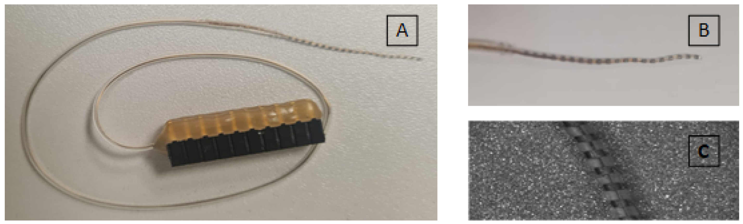
The electrode array is Oticon Medical’s Evo with 20 platinum–iridium electrodes. The EA has an active length of 24 mm. As shown in
Figure 1A, electrodes are individually wired and connected to the 20-pin header socket. Electrodes are evenly spaced but their size reduces from basal to apical electrode, as shown in
Figure 1B,C.
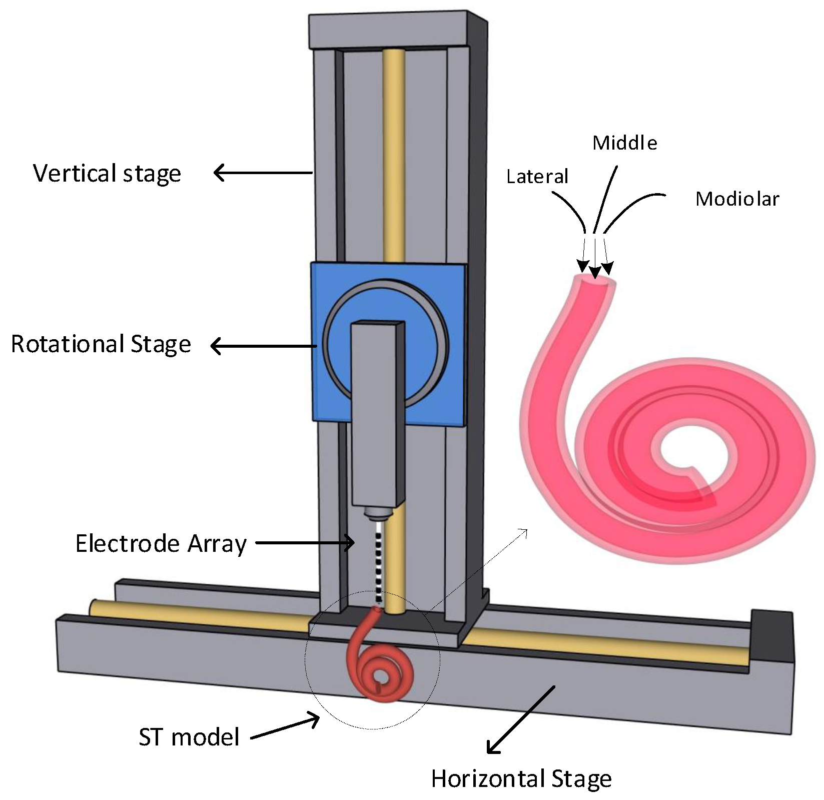
An actuation system shown in
Figure 2 was used for controlled insertion of EA in the ST model. This system has three DoF, where it can be moved horizontally, vertically and rotationally. The vertical stage was connected on the horizontal stage and the rotational stage was placed on the vertical stage. A holder was placed on the rotational stage to place EA for insertion. The EA was inserted from three different directions to form different trajectories during insertion.
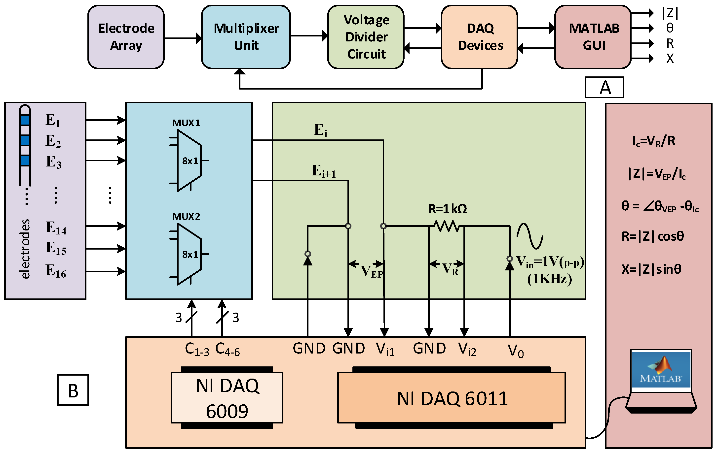
The overall configuration chain of impedance measurement and its detailed block diagram is shown in
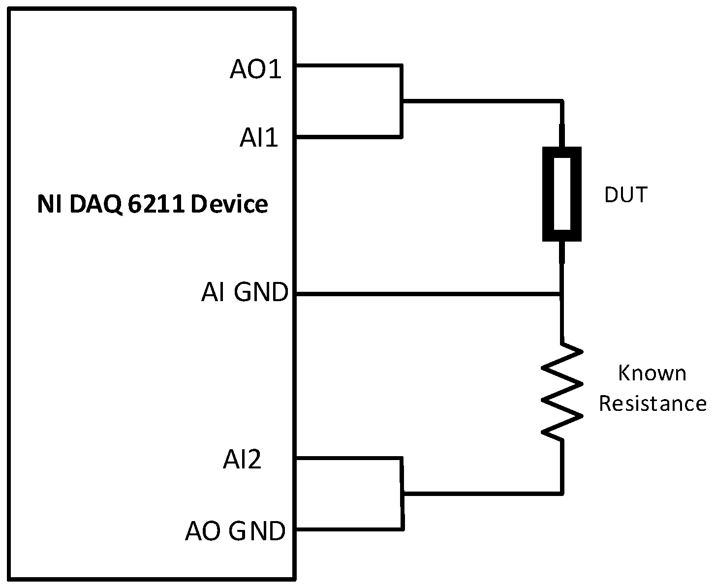
Figure 3. The EA was connected with the impedance meter through the female header connector. Bipolar impedances of electrode pairs were recorded using a voltage divider circuit, where DUT is an electrode pair (EP) in series with a known resistance, as shown in
Figure 4. A voltage signal 1 V p-p at 1 kHz frequency is applied to the series circuit through an NI DAQ 6211 device’s analogue output port, and voltages are recorded across both electrode pair and known resistance using the same device’s analogue input ports. The current through the circuit is calculated using the known resistance (
R) and voltage (
) across it using Ohm’s law, as shown in
Figure 3B. Impedance magnitude of the electrode pair is calculated using the relation
. The impedance phase is calculated by subtracting the current phase from the phase of voltage across EP. In our previous study, it was shown that impedance phase and its resistive and reactive parts are also useful for classification of different trajectories [
28]. Using geometrical representation, we can extract Cartesian coordinates (
R and
X) with the help of polar coordinates (|
Z| and
), as shown in
Figure 3B. We collected bipolar impedance magnitude (|
Z|), phase (
), resistance (
R), and reactance (
X) of eight electrode pairs. The setup configuration chain of the impedance meter is shown in
Figure 3A. EA is connected to the multiplexer that selects a certain EP to act as a DUT in the voltage divider circuit. NI DAQ devices (6211 and 6009) are responsible for all analogue input/output voltage signals and digital control signals to the multiplexer (
and
), respectively. These control signals select particular electrodes to make an EP. A custom MATLAB GUI application handles all the data input/output to the DAQ devices and processing to spit out the required features (|
Z|,
,
R, and
X). These features will further be used for our machine-learning-based prediction of trajectory and position of electrode array during the insertion.
2.2. Data Recording
The EA is inserted into a 2:1 scaled-up 2D plastic ST model 137 times in three different directions (medial, middle, lateral). The speed of insertion remained constant at 0.08 mm/s throughout the experiments. The data recording of four electrical features of eight EPs were carried out sequentially during the insertion. We found in our previous study that all four features mentioned above are important and even one pair of electrodes can give a reasonable prediction of electrode trajectory. In this study, we use data recordings of most apical electrode pairs for both offline and online trajectory prediction and correction. For every mm of insertion, there is one sample of each feature (|Z|, , R, X). Therefore, there would be n samples of each feature for n mm insertion ().
2.3. Offline Analysis
In our previous study, we concentrated only on full insertion prediction and partial insertion prediction using multiple EPs data only in the offline setting. In this study, machine learning algorithms, namely, shallow neural network (SNN) [
34], support vector machine (SVM) [
35], k-nearest neighbour (kNN) [
36], and random forest (RF) [
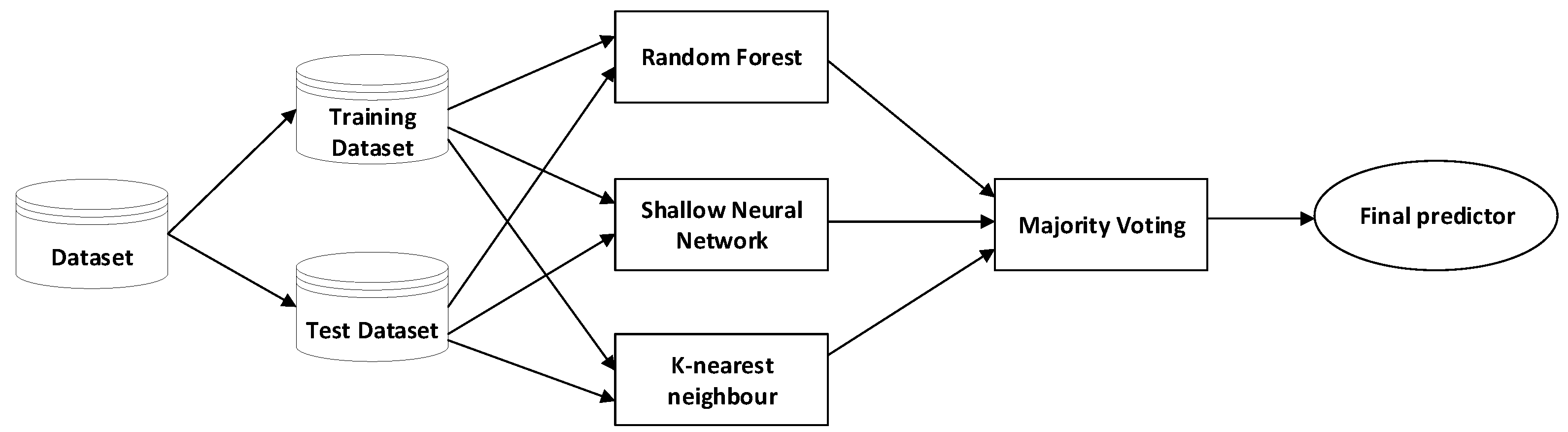
37], were used for offline analysis of trajectory and position prediction. Offline prediction entails recording of the data and then analysing it for prediction accuracy. In online (real-time when there are limits to latency) prediction, the trained model is tested in real time and its prediction accuracy is validated. Real-time prediction of trajectory and position of electrode array was carried out using only the most apical EP data recordings. An ensemble of the three best performing classifiers (SNN, kNN, and RF) with majority voting mechanism was chosen as our final predictor, as shown in
Figure 5.
2.4. Classifier-in-a-Loop System
Recently, advancements in machine learning techniques, sensing technologies, and computation capabilities in the control systems have led to increased interest in data-driven and learning-based control strategies [
38]. The vast generation of data by complex systems carry important information about the structure and operation of these systems, for example, data collected from brain, autonomous cars, unmanned aerial vehicles, and satellite navigation, to name a few. When a first-principle model is difficult to obtain and is complex, these data recordings can help scientists to understand, predict, classify, and ultimately control the behaviour of the system [
39].
For feedback control, one of the approaches utilizing sensor measurement data is to classify it into one of the finite sets of classes (situation), and each class corresponds to a known control action [
40]. In one of such research projects, image data were used to design a controller, using this technique to control a quadrotor to navigate a forest trail [
41]. Images were captured from three sides (left, centre, and right) of real-world hiking trails, and a multiclass (three) deep neural network classifier was trained and tested on these images. Real-time feedback controller was designed according to the three classes, for example, when an image is classified as right side of trail, the quadrotor will turn left, and so on. Based on this work, we have implemented our system using time series data acquired from an impedance sensing unit for EA optimized steering during cochlear implantation. A plastic ST perception technique based on machine learning algorithms was developed that bypasses the problem of determining the underlying characteristics of ST.
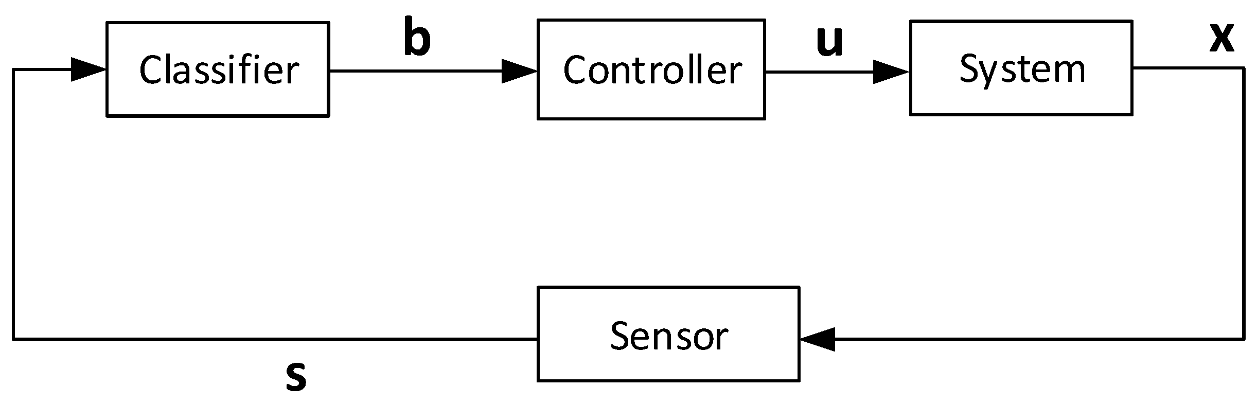
Let us consider a dynamical system shown in
Figure 6, where the dynamics of the system can be expressed as
In Equation (
1), state is represented as
and control input is
.
represents change in the state
x.
f is the function that defines the drift. From
Figure 6, the sensor generates the feature
and is dependent on the state
x, and their relationship is unknown. The classifier maps the feature
s to a unique label
. The aim of the classifier is to learn the weights
to minimize the error between the predicted label and the actual label associated with a certain feature vector. The set of labels
corresponds to the position of electrode array on the left, middle, or right of the ST model’s horizontal plane. The three labels are associated with three different control actions that the carrier has to implement for electrode array to stay in the middle of the ST (away from walls). These are the following:
- 1.
Move Left, if the array is touching the right (lateral) wall.
- 2.
Move Right, if the array is touching the left (modiolar) wall.
- 3.
Go Straight, if the array is in the middle.
The dataset consists of the features and the labels (
), where
j represents index of an example in the dataset. The classifier tries to find the relationship between the features and the labels. The feature vector
s depends on the state
x, so we can say that the classifier indirectly learns the mapping from state to the control. This way, the classifier generates the control input
u to the system and it results in a closed-loop feedback system, as shown in
Figure 6.
2.5. Problem Formulation
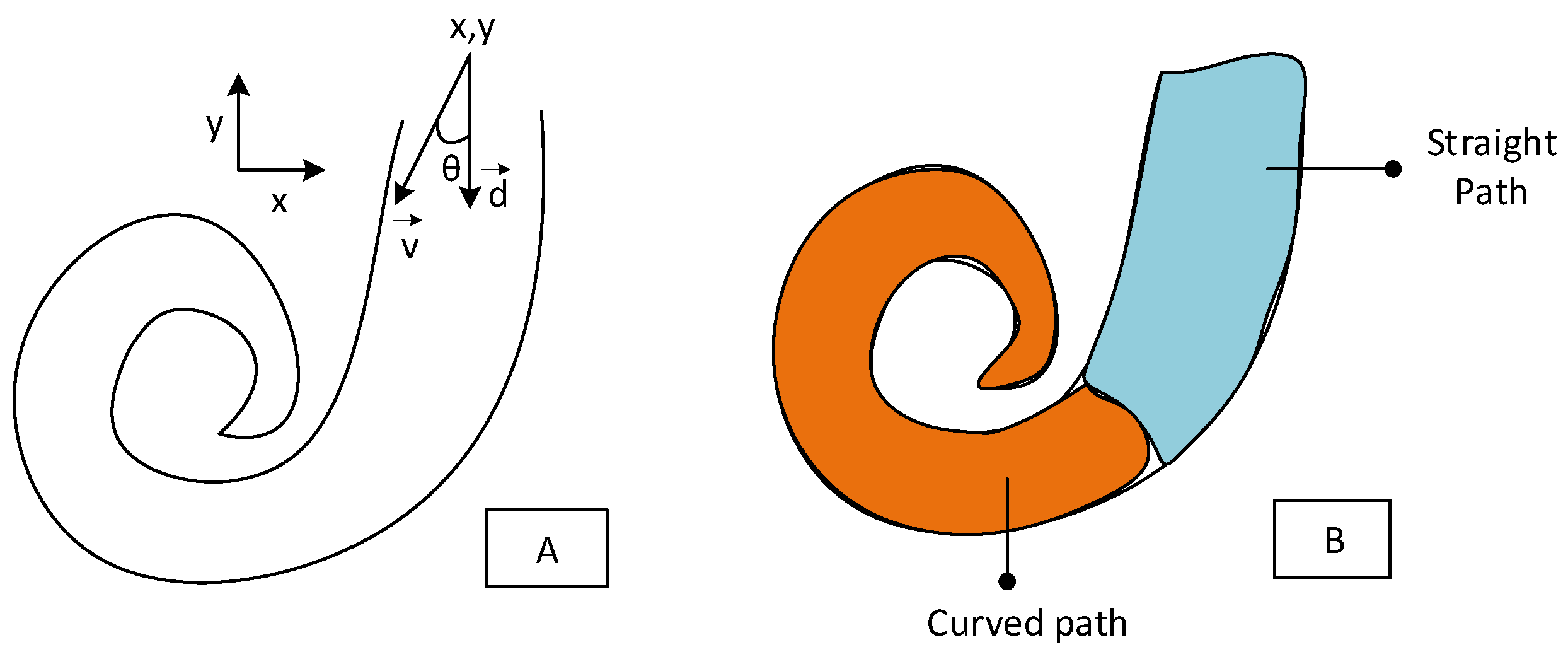
The insertion of the electrode array is configured such that it is presented as (
) in the plane where (
) points are considered as the location of array tip, and
angle represents heading of the array with respect to centre line of the ST model towards either of the modular/lateral walls (as depicted in
Figure 7A). Let
be the centre line trajectory of the electrode array and
be defined as direction of array insertion away from the centre line direction. The goal of the insertion is to keep the electrode array in the centre of the straight path of the ST model until it touches the curved path, where it slides along the curved path. The motivation of keeping the electrode array on the centre line trajectory is twofold: (1) it would not damage the delicate structure of the ST walls; (2) the centre line insertion imposes less overall force when the array touches the curved path and slides along it.
For this problem, we are considering the ST model as two paths; one is the straight path and the other is the curved path, as shown in
Figure 7B. One of the classification models would predict whether the position of the electrode array is located in the straight path or the curved path at a certain time. In this work, we will be generating the control signals for only the straight path, as we were unable to find any mechanism to control array in the curved path.
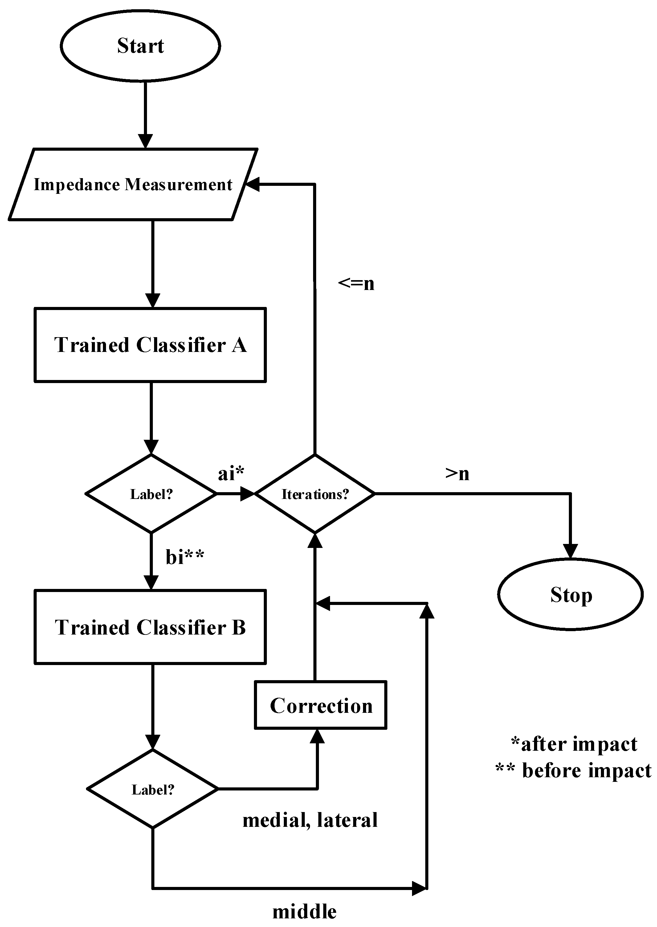
For real-time prediction, we have used two classifiers: (1) classifier A for trajectory prediction, and (2) classifier B for path/position prediction. Both classifiers would be trained on 4 mm subsequence data of the most apical electrode pairs because this is where most of the information about insertion is.
Although a reasonable accuracy has been achieved by our individual model, the ensemble approach has been used to increase the classification accuracy for both our classifiers. According to [
42], ensemble learning is the method in which multiple classifiers are combined to take their weighted vote to make predictions on new data. Each classifier makes its prediction and then votes for the final prediction, as shown in
Figure 5. This figure explains one of the ensemble learning processes that is called majority voting ensemble. In this kind of scheme, the final predictor would be the predictor that receives the majority vote from the multiple classifiers. In our setup, we have three classifiers (RF, SNN, and KNN) that achieved the maximum accuracy. Although it is possible to give uneven weights to the individual classifier vote, equal weight is given to each classifier in our system.
All the offline classification is carried out using Python 3.6, but in order to keep a homogeneous system along with actuation and sensing, a machine learning system is developed again in MATLAB. All the hyperparameters of learning models remain the same, and individual models are trained and tested again to make sure performance is kept the same as Python models. The ensemble majority voting algorithm is also developed in MATLAB.
Once we have ensemble-based trained models for both classifier A and B, we set up the system for real-time prediction and correction.
Figure 8 shows the control flow graph for real-time prediction and correction of the insertion trajectory. As mentioned above, this control strategy is for the straight path only to keep the electrode array at the centre line of the ST model. For this, there is a need to first predict whether the electrode array is in the straight path or the curved path.
3. Results
3.1. Offline Classification Results
The electrode array is inserted from three different angles and takes three different trajectories during the insertion process. In this analysis, generalization of four classification algorithms (SNN, KNN, SVM, RF) are looked into, using the partial insertion data of four electrical features (|Z|, , R, and X) of the most apical electrode pair. Additionally, this analysis is carried out on standardized raw data. After the data are organized for each segmentation scenario, machine learning models are trained and tested using a fivefold cross-validation procedure. For SNN, we used a multilevel perceptron (MLP) with two hidden layers of size 100 and 10, respectively, and finally a classification layer with three neurons. The hidden layers had an associated nonlinearity of rectified linear units (ReLU). A softmax layer was used to convert the output of the MLP into probabilities of the respective classes. The network was trained for 1000 epochs using an Adam optimizer at a learning rate of 0.001. For SVM, radial basis function (RBF) kernel function was used to train the data, dynamic time warping (DTW) was used as a distance metric, and five number of neighbours were used for the kNN classifier model. We did not use any weight class metric as our dataset is balanced. For the online prediction of trajectory, data from the most apical electrode pair (EP1) are used to train and test the algorithms first, and then we use the trained model for online prediction with the new collected data during the insertion process. Different length subsequences of EP1 data are used, that is, subsequence data collected during 4 mm, 3 mm, 2 mm, and 1 mm insertion. For these subsequences, a different set of data is assembled for analysis and only the straight path is considered for prediction and further correction. For example, for 4 mm insertion depth, two subsequences of four time samples each are extracted from each insertion example. These two subsequences will make two separate examples in the new dataset. That means now there would be 137 × 2 (274) examples in this dataset with respective targets (medial, middle, lateral). In the same way, for 3 mm subsequence, there will be three subsequences of three time samples each and each subsequence will make an example in the new dataset (137 × 3 = 411 examples) with respective target label. Moreover, new datasets for 2 mm and 1 mm subsequences have 137 × 4 = 548 and 137 × 8 = 1096 examples, according to the split of the straight path data. It is important to mention that we are using all four features (|Z|, , R, and X) in this analysis.
Table 1 shows the machine learning algorithms’ performances in terms of their cross-validated accuracies. As can be seen in the table, highest accuracy is achieved when 4 mm subsequences are used, and 2 mm subsequences came in second in terms of accuracy. The 1 mm subsequences achieved the lowest accuracy. This behaviour is attributed to SNN and kNN algorithms, whereas the accuracy decreases as the subsequence length is decreased from 4 mm–1 mm. In terms of the best-performing algorithms, SNN gave the best accuracy among the four algorithms cross-validated, while the SVM algorithm performed the worst.
For trajectory prediction, two methods of subsequencing were used and tested. Further analysis is carried out to predict whether the electrode array is in the straight path or the curved path during the insertion. For this, we use the full insertion data and split them into straight path and curved path data, labelling them accordingly. Since now we only have two classes (straight or curved), we term such problem as a binary classification. Different datasets are formed according to the subsequence length, labelled accordingly, and cross-validated on four machine learning models. For example, for 4 mm subsequence there will be two subsequence examples of straight path and three subsequence examples of curved path. That is, there will be five examples in the new dataset out of one example from the original dataset. The examples in the new dataset will be given target labels according to the path (straight or curved). The 4 mm-2C/3S dataset will have 137 × 5 = 685 examples to train and test using the algorithms. In the same way, new datasets, namely, 3 mm-3S/3C, 2 mm-4S/5C, and 1 mm-8S/10C, have 137 × 6 = 822, 137 × 9 = 1233, and 137 × 18 = 2466 examples, respectively.
Table 2 presents the accuracy results for the path prediction during the insertion process using different subsequence length datasets. These results show that as the subsequence length is decreasing, the accuracy of all algorithms also decreases. This is obvious because of the shorted length vector; we have less information available for prediction. However, the decrease is not linear due to increased number of examples on which the model is trained and tested, which makes generalization easier. As shown in
Table 2, again, the highest accuracy of 87.4% is achieved by SNN on 4 mm subsequences. Overall, SNN also outperformed other machine learning models in terms of accuracy. The lowest performer was the random forest model, with accuracy of 65.9% when 1 mm subsequences were used.
3.2. Real-Time Classifier-in-a-Loop System
Now there is enough evidence from our offline predictive analysis for machine learning algorithms to be used as an online/real-time classifier for electrode array steering during insertion. By this, we can achieve low force profiles during EA array insertion that could lead to less traumatic intraoperative behaviour. This online method is used for correction of the trajectory of the electrode array during the insertion based on the prediction of machine learning models.
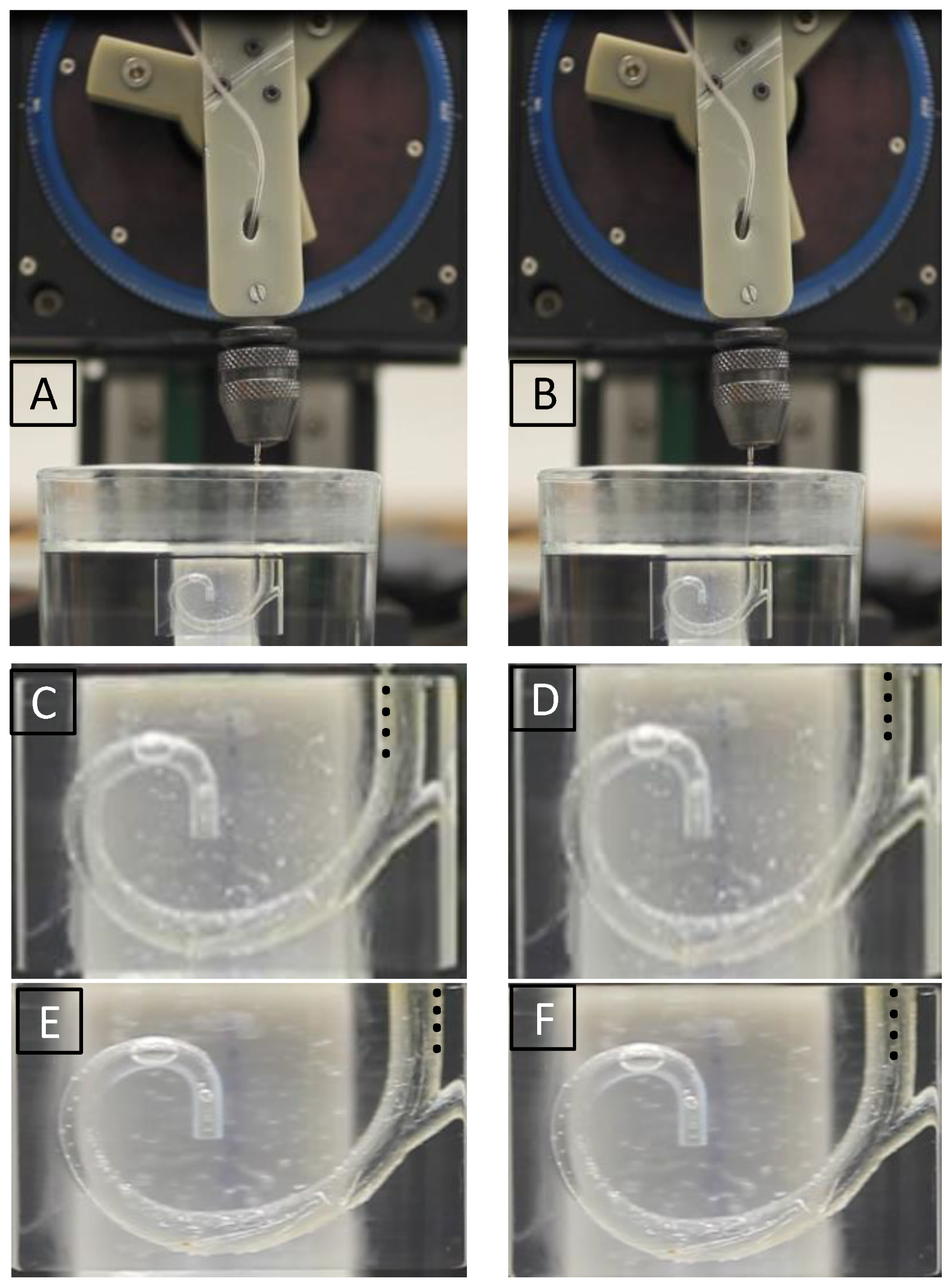
Figure 9 presents the pictorial representation of one of the real-time experiments. In
Figure 9A, the experimental setup is shown as the EA is inserted for 4 mm and data are collected, EA trajectory is towards the medial wall as EA can be seen inside the saline-filled ST model. A close-up of this trajectory is shown in (C). Once the recorded data vector is passed on to classifier A and classifier B, the controller makes the correction by moving the rotational stage of the actuator towards the right by
, as shown in
Figure 9B and in the close-up in (D). The trajectory could be towards the lateral wall, as shown in (E), and is corrected, as shown in (F).
Table 3 shows the ensemble learning classification results for both offline and real-time predictions. Ensemble learning models (classifier A and classifier B) are trained and tested first using three machine learning algorithms. The classifier A ensemble model achieved accuracy of 89.05%, which is an increase from 87.4%, when the highest performing individual model was used for path prediction. For classifier B, cross-validated accuracy of 86.86% was achieved using ensemble learning, which is slightly higher than the highest performing individual SNN model. For online prediction, 30 iterations were performed to test both classifier ensemble models. Classifier A achieved 83.33% accuracy, whereas classifier B achieved slightly lower accuracy of 80%, when tested for online prediction and correction.
4. Discussion
This study presents an important aspect and procedure for a robotic system aimed for use in electrode array insertion in cochlear implantation to avoid trauma. A novel system is developed for online prediction and correction of trajectory of the electrode array during electrode array insertion. This presents an application of an ensemble of machine learning algorithms for real-time closed-loop feedback control of an in vitro insertion process of an electrode array in cochlear implantation. It is the first step in this domain to develop a feedback controller for a robotic surgical procedure that can learn from its past experience and acquire the relationship between operating conditions and optimum actions. Data-driven machine learning models are trained and tested for trajectory (medial, lateral, and middle) and path (straight or curved) predictions during the insertion process. Overall, the shallow neural network achieved the highest performance in terms of accuracy. However, in order to improve performance, an ensemble learning approach was adopted with majority voting scheme. The ensemble learning model was developed with three machine learning algorithms, namely, shallow neural network, k-nearest neighbours, and random forest. Finally, our ensemble method achieved >80% accuracy for both offline and online trajectory and position/path classification.
It has been demonstrated successfully in this work that complex impedance has merit as a sensing modality for atraumatic steering of an electrode array. However, other sensing mechanisms introduced in this domain, such as force sensing [
43,
44], electrocochleography (EcochG) [
45], or facial nerve stimulation measurement unit [
46], can be integrated into a single unit along with complex impedance. Data generated by these sensing systems would carry more information about the EA insertion in real time than a single sensing system. This is termed data fusion, where data from different sources (sensors) are combined to reduce uncertainties, improve reliability, and increase the performance of the machine learning models [
47]. It would also be interesting to correlate complex impedance with the insertion forces and train the ML models to stop the insertion when a certain threshold is exceeded to avoid intraoperative damage.
As we have used classical machine learning algorithms for our trajectory prediction, there is a need to collect more data and test deep learning models that are believed to have more generalization ability and high performance. However, these deep learning models are data-hungry and they tend to overfit with few data examples. To record large datasets, we have to look at the reliability of the electrode array as well, since it is not made for the purpose of inserting hundred and thousands of times to collect large amounts of data. We may overcome this problem either with the availability of a decent amount of electrode arrays or we can apply data augmentation techniques to generate synthetic data [
48].
We have proposed a solution for the trajectory and path/position prediction and correction of an electrode array using bipolar complex impedance measurements. This system may be helpful in predicting insertion failures such as tip foldover (this problem is more pronounced in perimodiolar EAs), EA bucking, and EA translocation. Further experiments need to be performed to demonstrate its applicability to overcome such failures that not only degrade CI postoperative performance but could also lead to internal infections.
This system is open to further development and can be beneficial for automatic steering of an EA during insertion. The system is tested using the most apical EP and in the straight path only. It can be extended to other EPs and to the curved path as well, given that a novel actuation scheme is developed alongside to steer the EA in the curved path. The system presented can also find application in other electrode insertion applications and also in needle steering.


 ,
, 
