
Modeling and Simulation of a Two-Stage Air-Cooled Adsorption Chiller with Heat Recovery Part II: Parametric Study


Abstract
:1. Introduction
2. Physical and Mathematical Models
2.1. Physical Model
Modes of Operation for Two-Stage Adsorption Chiller
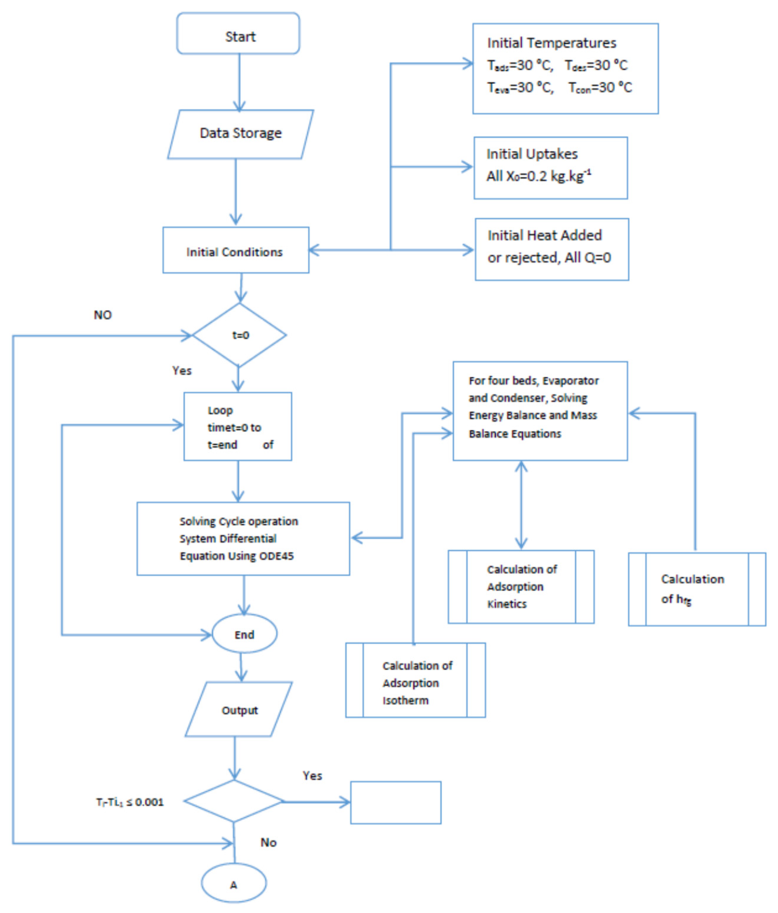
2.2. Mathematical Model
3. Results and Discussion
3.1. Effect of the Mass of Activated Carbon
3.2. Effect of Evaporator Overall Heat Transfer Coefficient
3.3. Effect of Bed’s Overall Heat Transfer Coefficient
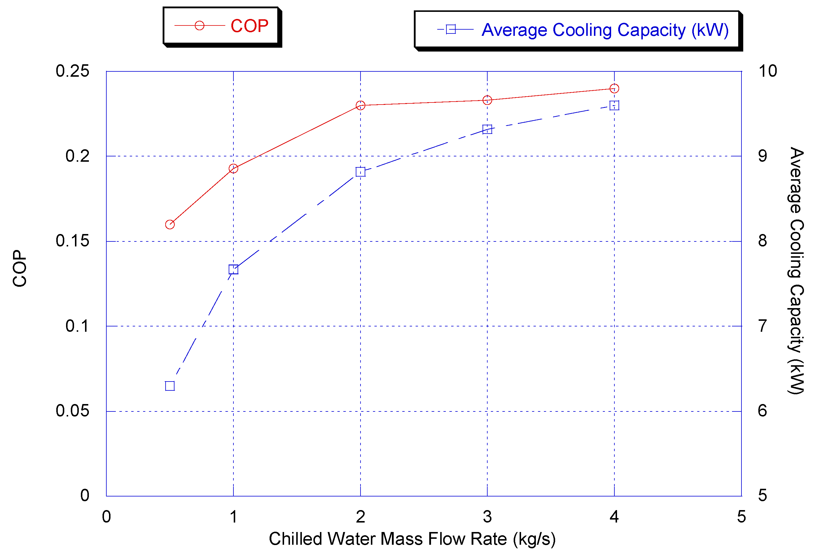
3.4. Effect of Chilled Water Mass Flow Rate
3.5. Effect of Cooling Water Mass Flow Rate
3.6. Effect of Hot Water Mass Flow Rate
3.7. Effect of Condenser Water Mass Flow Rate
3.8. Effect of Cooling Water Inlet Temperature
3.9. Comparison with Carnot Cycle COP
3.10. Model Results at Optimum Parametric Values
3.11. Preliminary Study for the Extension of the Models for Larger Chiller Capacity
4. Conclusions
- The dynamic model could predict all sizes for the two-stage chiller using an activated carbon/methanol pair, and easily could be adapted for any working pairs at variable operating conditions.
- The two-stage chiller could be operated by using low-grade waste heat at low COP or at a high temperature heat source with moderate to high COP.
- The proposed model could predict the COP for any chiller size with 90–95% of a Carnot cycle chiller working the same as an operating chiller at temperatures as low as 60 °C with heat recovery between beds.
- The model is a useful tool to predict the effect of the changing of mass of activated carbon mass and the heat transfer coefficient of beds, evaporator and condenser.
- The model is a useful tool to predict the effect of the flow rate of cooling and heating water in addition to the effect of chiller and condenser flow rates on chiller cooling capacity and COP.
- The model is a useful tool to predict the effect of inlet temperature of cooling and heating water on chiller cooling capacity and COP.
- The two-stage air-cooled adsorption chiller has a significant market potential, and the model used in this study could be used as a base for prototype scaling or series production.
Subscript
| ac | activated carbon |
| ad | adsorption |
| Al | Aluminum |
| b | bed |
| ci | cooling inlet |
| co | cooling outlet |
| cw | cold water |
| chw | chilled water |
| conw | condenser water |
| con | condenser |
| des | desorption |
| eva | evaporator |
| fg | vaporization |
| g | gas |
| hw | hot water |
| i | inlet |
| o | outlet |
| recw | recalculated water |
| s | solid |
| sat | saturation |
| st | storage |
Author Contributions
Funding
Institutional Review Board Statement
Informed Consent Statement
Conflicts of Interest
Appendix A

Appendix B

| Symbol | Value | Unit |
|---|---|---|
| Abed | 4.5 | m2 |
| Aeva | 3 | m2 |
| Acon | 3 | m2 |
| Ubed | 3 | kW/m2·°C |
| Ueva | 2 | kW/m2·°C |
| Ucon | 4 | kW/m2·°C |
| Cpeva | 0.65 | kJ/kg·°C |
| Cpcon | 0.65 | kJ/kg·°C |
| Cpw | 4.18 | kJ/kg·°C |
| Cpac | 1 | kJ/kg·°C |
| Cpm | 2.6 | kJ/kg·°C |
| ρ (activated carbon) | 2000 | Kg/m3 |
| kac (activated carbon) | 0.63 | W/m·k |
| Meva | 20 | kg |
| Mcon | 30 | kg |
| hfg | 1200 | kJ·kg−1 |
| Mac | 40 | kg |
| Meva,m | 20 at time = 0 | kg |
| Mcon,m | 5 | kg |
| (E/R) Methanol | 978 | K |
| (15 Dso/R) Methanol | 7.35 × 10⁻² | S−1 |
| xo | 0.284 | kg·kg−1 |
| n | 1.39 | Non Dimensional |
| K | 10.21 | Non Dimensional |
| R1 | 260 | Non Dimensional |
| Q | 4.666 | Non Dimensional |
| A | 20.84 | Non Dimensional |
| B | 4696 | Non Dimensional |
Appendix C
| Symbol | Value | Unit |
|---|---|---|
| Thi | 95 | °C |
| Tci | 30 | °C |
| Tconi | 30 | °C |
| Tchi | 15 | °C |
| Mchw | 2 | kg·s−1 |
| Mcw | 1 | kg·s−1 |
| Mhw | 1.5 | kg·s−1 |
| Mconw | 2 | kg·s−1 |
| Mrecw | 1 | kg·s−1 |
| Adsorption time | 300 | s |
| Desorption time | 300 | s |
| Switching time | 50 | s |
| Heat recovery time | 30 | s |
Appendix D
| Symbol | Value | Unit |
|---|---|---|
| Thi | 95 | °C |
| Ub | 3 | kW/m2·°C |
| Ueva | 1 | kW/m2·°C |
| Tchi | 15 | °C |
| Mchw | 3 | kg·s−1 |
| Mcw | 1 | kg·s−1 |
| Mhw | 1.5 | kg·s−1 |
| Mconw | 2 | kg·s−1 |
| Mrecw | 1 | kg·s−1 |
| Adsorption time | 300 | s |
| Desorption time | 300 | s |
| Switching time | 50 | s |
| Heat recovery time | 30 | s |
Appendix E
| Symbol | Description | Unit |
|---|---|---|
| Abed | Bed area | (m2) |
| Aeva | Evaporator area | (m2) |
| Acon | Condenser area | (m2) |
| Cp | Specific heat capacity | (kJ/kg·°C) |
| CC | Cooling Capacity | (kW) |
| COP | Coefficient of Performance | (Cooling capacity/input power) |
| Dso | Surface specific heat | (m2·s−1) |
| Ea | Activation energy | (kJ) |
| hfg | Latent heat of vaporization | (kJ·kg−1) |
| H | Enthalpy | (kJ·kg−1) |
| K | Constant in D-A equation | Non dimensional |
| Meva | Evaporator mass | (kg) |
| Mcon | Condenser mass | (kg) |
| Mac | Mass of activated carbon in each bed | (kg) |
| Meva,m | Mass of methanol in evaporator at t = 0 | (kg) |
| Mcon,m | Mass of methanol in condenser | (kg) |
| N | Constant in D-A equation | Non dimensional |
| P | Pressure | (Bar) |
| Qst | Adsorption heat | (kJ·kg−1) |
| R | Universal gas constant | (kJ/mol·K) |
| T | Temperature | (°C) |
| T | Time | (S) |
| Ubed | Bed overall heat transfer coefficient | (kW/m2·°C) |
| Ueva | Evaporator overall heat transfer coefficient | (kW/m2·°C) |
| Ucon | Condenser overall heat transfer coefficient | (kW/m2·°C) |
| X | Methanol concentration | (kg·kg−1) |
| xo | Maximum methanol concentration | (kg·kg−1) |
| x* | Equilibrium methanol concentration | (kg·kg−1) |
References
- Makahleh, F.; Amer, A.; Attar, H.; Badran, A. Modeling and simulation of a two stage adsorption chiller with heat recovery Part 1. Appl. Sci. 2022; Under review. [Google Scholar]
- Krzywanski, J.; Grabowska, K.; Sosnowski, M.; Żyłka, A.; Sztekler, K.; Kalawa, W.; Wójcik, T.; Nowak, W. Modeling of a re-heat two-stage adsorption chiller by AI approach. MATEC Web Conf. 2018, 240, 05014. [Google Scholar] [CrossRef]
- Benrajesh, P.; Rajan, A.J. Design and Analysis of a Two-Stage Adsorption Air Chiller. IOP Conf. Ser. Mater. Sci. Eng. 2017, 197, 012030. [Google Scholar] [CrossRef] [Green Version]
- Sosnowski, M.; Grabowska, K.; Krzywański, J.; Nowak, W.; Sztekler, K.; Kalawa, W. The effect of heat exchanger geometry on adsorption chiller performance. IOP Conf. Ser. J. Phys. Conf. Ser. 2018, 1101, 012037. [Google Scholar] [CrossRef] [Green Version]
- Schwamberger, V.; Desai, A.; Schmidt, F.P. Novel Adsorption Cycle for High-Efficiency Adsorption Heat Pumps and Chillers: Modeling and Simulation Results. Energies 2020, 13, 19. [Google Scholar] [CrossRef] [Green Version]
- Jobard, X.; Padey, P.; Guillaume, M.; Duret, A.; Pahud, D. Development and Testing of Novel Applications for Adsorption Heat Pumps and Chillers. Energies 2020, 13, 615. [Google Scholar] [CrossRef] [Green Version]
- Lee, J.-G.; Bae, K.J.; Kwon, O.K. Performance Investigation of a Two-Bed Type Adsorption Chiller with Various Adsorbents. Energies 2020, 13, 2553. [Google Scholar] [CrossRef]
- Rouf, R.A.; Jahan, N.; Alam, K.C.A.; Sultan, A.A.; Saha, B.B.; Saha, S.C. Improved cooling capacity of a solar heat driven adsorption chiller. Case Stud. Therm. Eng. 2020, 13, 1–19. [Google Scholar] [CrossRef]
- Al Asfar, J.; Ayadi, O.; Al Salaymeh, A. Design and Performance Assessment of a Parabolic Trough Collector. JJMIE 2014, 8, 1–5. [Google Scholar]
- Abd-Elhady, M.M.; Hamed, A.M. Effect of fin design parameters on the performance of a two-bed adsorption chiller. Int. J. Refrig. 2020, 113, 164–173. [Google Scholar] [CrossRef]
- Basdanis, T.; Tsimpoukis, A.; Valougeorgis, D. Performance optimization of a solar adsorption chiller by dynamically adjusting the half-cycle time. Renew. Energy 2021, 164, 362–374. [Google Scholar] [CrossRef]
- Zhai, Q.; Wang, R.Z.; Wu, J.Y.; Dai, Y.J.; Ma, Q. Design and performance of a solar-powered air-conditioning system in a green building. Appl. Energy 2008, 4, 267. [Google Scholar]
- Sakoda, A.; Suzuki, M. Fundamental Study on Solar Powered Adsorption Cooling System. Chem. Eng. Jpn. 1984, 17, 52–57. [Google Scholar] [CrossRef] [Green Version]
- Khan, M.Z.I.; Alam, K.C.A.; Saha, B.B.; Hamamoto, T.; Akisaw, A.; Kashiwagi, T. Parametric Study of A Two Stage Adsorption Chiller Using Reheat:The Effect of the Overall Thermal Conductance and Adsorbent Mass on System Performance. Int. J. Therm. Sci. 2006, 45, 511–519. [Google Scholar] [CrossRef]
- Alam, K.C.A.; Saha, B.B.; Hamamoto, T.; Akisaw, A.; Kashiwagi, T. Influence of Design and Operating Conditions on The Performance of A Two-Stage Adsorption Chiller. Chem. Eng. Commun. 2006, 91, 981–997. [Google Scholar] [CrossRef]
- Stefański, S.; Mika, L.; Sztekler, K.; Kalawa, W.; Lis, L.; Nowak, W. Adsorption bed configure rations for adsorption cooling application. E3S Web Conf. 2019, 108, 01010. [Google Scholar] [CrossRef]
- Hassan, H.Z.; Ahmad, A.A.; Al-Ansary, H.A.A. Development of a continuously operating solar-driven adsorption cooling system: Thermodynamic analysis and parametric study. Appl. Therm. Eng. 2012, 48, 332–341. [Google Scholar] [CrossRef]
- Ahmed, R.M.; Rezk, R.; Al-Dadah, K. Physical and Operating Conditions Effect on Silica gel/water Adsorption Chiller Performance. Appl. Energy 2012, 89, 142–149. [Google Scholar]
- Alam, K.C.A.; Saha, B.B.; Akisawa, A.; Kashiwagi, T. A Novel Parametric Analysis of a Conventional Silica-Gel Water Adsorption Chiller. ASHRAE Trans. 2011, 17, 323–332. [Google Scholar]
- Papoutsis, E.G.; Koronaki, I.P.; Papaefthimiou, V.D. Parametric Study of a Single-Stage Two-Bed Adsorption Chiller. J. Energy Eng. 2017, 143, 04016068. [Google Scholar] [CrossRef]
- Angrouza, Y.; Bouhal, T.; Alluhi, A.A.; Kouskou, T.; Zeraouli, J.Y. Energy and parametric analysis of solar absorption cooling systems in various Moroccan climates. Case Stud. Therm. Eng. 2017, 9, 28–39. [Google Scholar]
- Mohammed, R.H.; Mesalhy, O.; Elsayed, M.L.; Chow, L.C. Compact bed design for adsorption cooling systems: Parametric numerical study Conception. Int. J. Refrig. 2012, 80, 238–251. [Google Scholar] [CrossRef]
- PapoutsisI, E.G.; Koronaki, P.; Papaefthimiou, V.D. Numerical simulation and parametric study of different types of solar cooling systems under Mediterranean climatic conditions. Energy Build. 2017, 138, 601–611. [Google Scholar] [CrossRef]
- Al-Rbaiha, R.; Sakhrieh, A.; Al-Asfar, J.; Alahmer, A.; Ayadi, O.; Al-Salaymeh, A.; Al_hamamre, Z.; Al-bawwab, A.; Hamdan, M. Performance Assessment and Theoretical Simulation of Adsorption refrigeration System Driven by Flat Plate Solar Collector. JJMIE 2017, 11, 1–11. [Google Scholar]
- Shaban, N.A.; Al-Salaymeh, A.; Maaitah, A. Performance and Evaluation of Adsorption Chillers Powered by Solar Energy by means of PTC’s in Jordan. In Proceedings of the JIIRCRAC’ 15, Aqaba, Jordan, 8–10 March 2015. [Google Scholar]


| Mode | A | B | C | D | E | F |
|---|---|---|---|---|---|---|
| G1 | Adsorption | Heat Recovery | Pre-Heating | Desorption | Heat Recovery | Pre-Cooling |
| G2 | Desorption | Heat Recovery | Pre-Cooling | Adsorption | Heat Recovery | Pre-Heating |
| G3 | Desorption | Heat Recovery | Pre-Cooling | Adsorption | Heat Recovery | Pre-Heating |
| G4 | Adsorption | Heat Recovery | Pre-Heating | Desorption | Heat Recovery | Pre-Cooling |
| Inlet Hot Temperature °C | Carnot Cycle COP | Model COP without Heat Recovery | Model COP with Heat Recovery | (HR Model COP/ Carnot COP) × 100% |
|---|---|---|---|---|
| 60 | 0.42 | 0.14 | 0.4 | 95 |
| 80 | 0.423 | 0.16 | 0.37 | 88 |
| 100 | 0.406 | 0.17 | 0.36 | 89 |
| 120 | 0.39 | 0.17 | 0.35 | 90 |
Publisher’s Note: MDPI stays neutral with regard to jurisdictional claims in published maps and institutional affiliations. |
© 2022 by the authors. Licensee MDPI, Basel, Switzerland. This article is an open access article distributed under the terms and conditions of the Creative Commons Attribution (CC BY) license (https://creativecommons.org/licenses/by/4.0/).
Share and Cite
Makahleh, F.M.; Badran, A.A.; Attar, H.; Amer, A.; Al-Maaitah, A.A. Modeling and Simulation of a Two-Stage Air-Cooled Adsorption Chiller with Heat Recovery Part II: Parametric Study. Appl. Sci. 2022, 12, 5156. https://doi.org/10.3390/app12105156
Makahleh FM, Badran AA, Attar H, Amer A, Al-Maaitah AA. Modeling and Simulation of a Two-Stage Air-Cooled Adsorption Chiller with Heat Recovery Part II: Parametric Study. Applied Sciences. 2022; 12(10):5156. https://doi.org/10.3390/app12105156
Chicago/Turabian StyleMakahleh, Firas M., Ali A. Badran, Hani Attar, Ayman Amer, and Ayman A. Al-Maaitah. 2022. "Modeling and Simulation of a Two-Stage Air-Cooled Adsorption Chiller with Heat Recovery Part II: Parametric Study" Applied Sciences 12, no. 10: 5156. https://doi.org/10.3390/app12105156
APA StyleMakahleh, F. M., Badran, A. A., Attar, H., Amer, A., & Al-Maaitah, A. A. (2022). Modeling and Simulation of a Two-Stage Air-Cooled Adsorption Chiller with Heat Recovery Part II: Parametric Study. Applied Sciences, 12(10), 5156. https://doi.org/10.3390/app12105156