Article

Hole Cleaning Performance of V-Shaped Hole Cleaning Device in Horizontal Well Drilling: Numerical Modeling and Experiments

1
CNOOC Research Institute Company Limited, Beijing 100028, China
2
Southern Marine Science and Engineering Guangdong Laboratory (Zhanjiang), Zhanjiang 524013, China
3
Department of Engineering and Applied Science, Memorial University of Newfoundland, St. John’s, NF A1B3X5, Canada
4
College of Petroleum Engineering, Northeast Petroleum University, Daqing 163318, China
*
Author to whom correspondence should be addressed.
Appl. Sci. 2022, 12(10), 5141; https://doi.org/10.3390/app12105141
Submission received: 23 April 2022 / Revised: 14 May 2022 / Accepted: 16 May 2022 / Published: 19 May 2022
(This article belongs to the Special Issue Multiphase and Granular Flows)

Abstract

:
The application of hole cleaning devices can effectively solve the hole cleaning problem during the drilling of horizontal wells. Improving the hole cleaning performance is directly related to subsequent drilling time and cost. In this paper, the solid–liquid two-phase hydrodynamic characteristics under the action of the V-shaped hole cleaning device for drilling horizontal wells were studied experimentally and numerically. The decay law of spiral flow induced by the V-shaped hole cleaning device was obtained numerically using the commercial CFD code “Fluent” by changing the blade rotational speed, blade helix angle, and consistency coefficient of drilling fluid. The helix angle will cause the flow direction of local fluid to deflect. The swirl intensity of spiral flow increases significantly with an increase in rotational speed. The hole cleaning performance was better when the helix angle was from about 10 to 20 degrees. Increasing the fluid consistency coefficient will rapidly make the spiral flow decay, resulting in a shorter effective action distance and a worse hole cleaning effect. The simulation results were validated against the experimental results of the flow loop. Both experimental and simulation results showed that the hole cleaning performance was improved by using the V-shaped hole cleaning device. The very good agreement achieved between the results has presented an opportunity to study the hole cleaning effect of a hole cleaning device in unsteady state conditions. The results will provide theoretical guidance for efficient hole cleaning using V-shaped hole cleaning devices for horizontal well drilling.

1. Introduction

With the increasing demand for oil and gas resources and the continuous progress in production methods, extended-reach and horizontal well technology have made remarkable developments [1,2]. However, during extended-reach and horizontal well drilling, it is easy for drill cuttings to be deposited in the horizontal well section, resulting in a cuttings bed. With the increase in drilling time, the accumulation and thickening of the cuttings bed can easily cause drilling problems such as pipe sticking, high torque, and drag [3,4]. This will increase the drilling risk, limit the horizontal well’s extension capacity, and significantly increase the drilling period and cost [5,6,7].
The hole cleaning device can effectively remove the cuttings bed during extended-reach and horizontal well drilling. It can accelerate the flow of drilling fluid. At the same time, the rotation of the hole cleaning device can form a vortex in the spiral channel, which is more conducive to removing drill cuttings, improving the circulation velocity in the annulus, and effectively eroding the cuttings bed. The combination of mechanical rotation and hydrodynamic eddy current effect of the hole cleaning device can effectively remove cuttings and ensure the hole cleaning effect.
Such research for hole cleaning devices has been rapidly developing worldwide in recent years. In 1999, Halliburton developed and produced the cuttings bed Impeller (CBI). Its main structure includes a tool body, herringbone diversion groove, and transition section. The CBI mainly comprises the body, the transition slope diversion, the neck, the export diversion slope, the spiral-shaped impeller, the spiral-shaped groove, and the inlet diversion slope [8,9].
Later, VAM Drilling company launched a HydrocleanTM particular structure drill pipe to solve the cuttings bed accumulated in the highly deviated and horizontal sections. The hole cleaning mechanism of HydrocleanTM particular structure drill pipe uses the mechanism of mechanical scraping and hydraulic lifting of drilling fluid. When drilling the highly deviated and horizontal wells, the high-speed rotation of the spiral blade will generate a circumferential force outside the blade (the force depends on the rotating drill pipe) to stir the cuttings bed. Using HydrocleanTM can improve the hole cleaning efficiency by 55% to 60%, reduce the torque and drag by 25% to 35%, and reduce the annular pressure consumption by more than 45% [10,11].
Recently, Qu et al. [12] simplified the hole cleaning device into a straight blade; obtained the decay mechanism of spiral flow; and evaluated the hole cleaning effect under different helix angles, blade heights, and rotational speeds. Yan et al. [13] used the CFD method to obtain the effective action distance of a straight-blade type hole cleaning device under different parameters and took the effective action distance to evaluate the hole cleaning effect. The numerical results showed that the hole cleaning device has a sound hole cleaning performance.
With such in-depth study about the design and optimization of hole cleaning devices, people’s theoretical understanding of them is deepening [14]. However, detailed research on the existing V-blade hole cleaning devices in the drilling engineering field is limited. At the same time, most of the drilling fluid is non-Newtonian fluid [15,16]; the decay characteristics of device-induced spiral flow in a non-Newtonian fluid, flow pattern distribution behind the blade, and the hole cleaning effect are not completely clear.
In this paper, the solid–liquid flow characteristics of a V-shaped hole cleaning device were simulated utilizing CFD approach. The decay law of spiral flow induced by the V-shaped hole cleaning device was obtained by changing the rotational speed, fluid consistency coefficient, and helix angle. In addition, the annular cuttings concentration distribution under different parameters was also obtained. The main contribution of this paper is to reveal the mechanism of spiral flow induced by the V-shaped hole cleaning device and its influence on the hole cleaning effect, which is a significant reference for the structural optimization and improvement of the V-shaped hole cleaning device.

2. Methodology

2.1. Governing Equations

The Eulerian–Eulerian Two-Fluid Model (TFM) is used for the numerical simulation. The TFM method has been fully proved in the literature and is widely recognized in engineering [17,18,19]. For simplicity, it is assumed that the solid phase consists of spherical particles with the same particle size.
The mass conservation equation for drilling fluid and drill cuttings are as follows:
t ( α l ρ l ) + ( α l ρ l u l ) = 0
t ( α s ρ s ) + ( α s ρ s u s ) = 0
where α is the volume fraction; ρ is the density; u is the velocity; and subscripts l and s represent drilling fluid and cuttings, respectively.
The momentum conservation equation for drilling fluid and drill cuttings are as follows:
t ( α l ρ l u l ) + ( α l ρ l u l u l ) = α l p + α l τ l ¯ ¯ + α l ρ l g β ( u l u s )
t ( α s ρ s u s ) + ( α s ρ s u s u s ) = α s p p s + α s τ s ¯ ¯ + α s ρ s g + β ( u l u s )
where g is the acceleration of gravity; p is the pressure; τ is the stress tensor; and β is the inter-phase momentum exchange coefficient, predicted by the Huilin–Gidaspow model [20].
β = φ β Ergun + ( 1 φ ) β Wen & Yu
φ = arctan [ 262.5 ( α s 0.2 ) ] π + 0.5
for αl ≤ 0.8,
β Ergun = 150 α s 2 μ l α l d s 2 + 1.75 ρ l α s | u l u s | d s
for αl > 0.8,
β Wen & Yu = 3 4 C D α s α l ρ l | u l u s | d s α l 2.65
where ds is the cuttings diameter and CD is the drag coefficient:
C D = { 24 R e s ( 1 + 0.15 R e s 0 . 687 ) R e s 1000 0.44 R e s > 1000
The stress tensor of each phase is calculated as follows:
τ l ¯ ¯ = μ l { [ u l + ( u l ) T ] 2 3 ( u l ) I = }
τ s ¯ ¯ = μ s [ u s + ( u s ) T ] + ( ξ s 2 3 μ s ) ( u s ) I =
where I = is the unit tensor, μ is the shear viscosity, ξ s is the bulk viscosity of solids, and ps is the solids pressure.
The solids pressure is defined as follows:
p s = α s ρ s Θ s + 2 ρ s ( 1 + e ) α s 2 g 0 Θ s
where e is the restitution coefficient, Θ s is the granular temperature, and g0 is the radial distribution function and can be written as follows:
g 0 = [ 1 ( α s α smax ) 1 3 ] 1
The bulk viscosity of solids is defined as follows:
ξ s = 4 3 α s 2 ρ s d s g 0 ( 1 + e ) Θ s π
The solids shear viscosity is defined as follows:
μ s = 4 5 α s ρ s d s g 0 ( 1 + e ) Θ s π + 10 ρ s d s π Θ s 96 ( 1 + e ) α s g 0 [ 1 + 4 5 g 0 α s ( 1 + e ) ] 2
The granular temperature transport equation is calculated as follows:
0 = ( p s I ¯ ¯ + τ s ¯ ¯ ) : u s γ Θ s + ϕ ls
where ( p s I ¯ ¯ + τ s ¯ ¯ ) : u s is the generation of energy by the solid stress tensor, γ Θ s is the collisional dissipation of energy, and ϕls is the energy exchange between the fluid and solid phases.
In this study, the realizable k-ε turbulence model was used as a turbulence closure model. The turbulence kinetic energy k and the dissipation rate ε were obtained from the following transport equations [21,22,23].
( ρ l k ) t + ( ρ l k u j ) x j = x j [ ( μ l + μ t σ k ) k x j ] + G k ρ l ε
( ρ l ε ) t + ( ρ l ε u j ) x j = x j [ ( μ l + μ t σ ε ) ε x j ] + ρ l C 1 S ε ρ l C 2 ε 2 k + μ l ρ l ε
where Gk represents the generation of turbulence kinetic energy due to the mean velocity gradients and μ t = ρ l C μ k 2 / ε is the turbulent viscosity of the fluid. The related empirical constants are C 1 = max [ 0.43 , η η + 5 ] , η = S k ε , σ k = 1.0 , σ ε = 1.2 and C 2 = 1.9 .

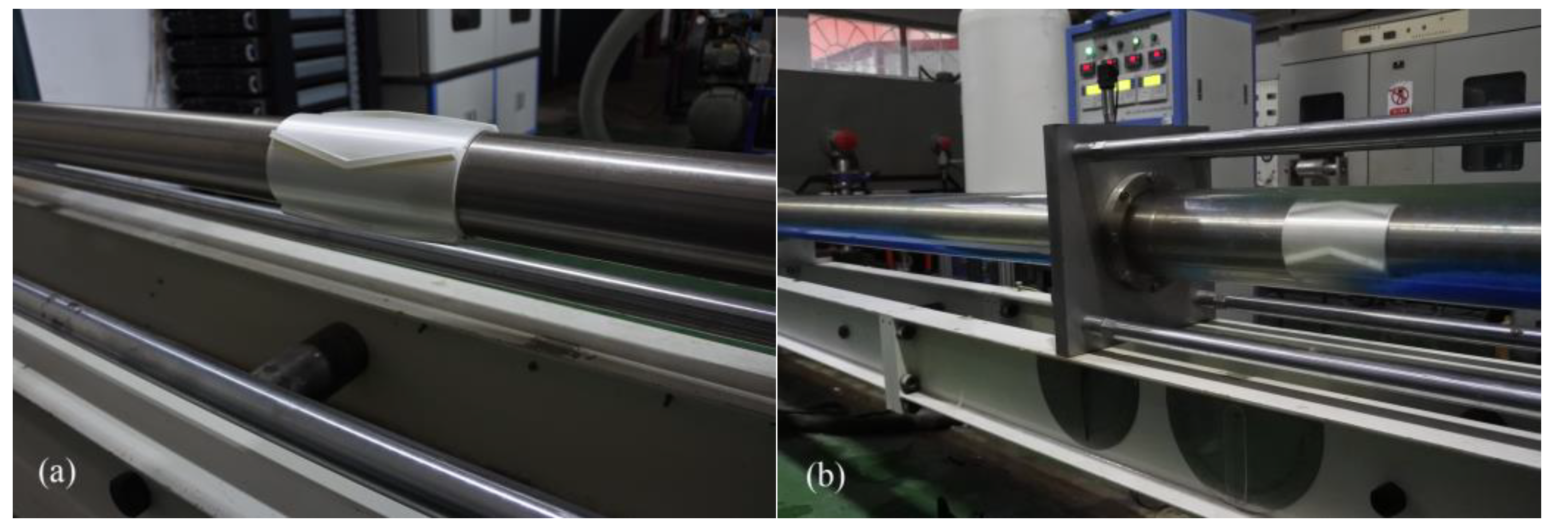
2.2. Experimental and Numerical Setup

The configuration of the experimental flow loop was an annulus, and the annular length was 5500 mm. The overall length of the V-shaped hole cleaning device was 150 mm, and the device was placed 1000 mm away from the annulus inlet, as displayed in Figure 1. The Carboxyl–Methyl–Cellulose (CMC) solution was selected as the experimental drilling fluid, and the rheological parameters of the fluid were measured by the Anton Paar rheometer (MCR 92). A high-speed camera (Revealer 2F04C) was used to capture the cuttings transport process [24]. The simulated drill cuttings were selected as spherical glass beads with diameters of 2 mm.
When the cuttings bed reached a stable state, the transparent ruler on the outer wall of the wellbore was recorded in detail to calculate the arc length and to convert it into the cuttings bed height. At the same time, it could also measure the effective action distance under the action of the hole cleaning device. To minimize any uncertainty, each experiment was repeated in three replications, and their average values were taken.
The geometry of blades mainly includes the blade height and blade helix angle. In this paper, only the influence of helix angle is considered. Due to the complex downhole working conditions, the blade height could not be designed too large. The maximum allowable height is only designed regarding the height of the drill pipe joint.
Other physical parameters and wellbore structure parameters are summarized in Table 1.
The numerical setup was modeled based on the experimental setup so that all dimensions and operation conditions were equal. A velocity-inlet boundary condition was used as the inflow condition; a pressure-outlet boundary condition was used as the outflow. The no-slip boundary conditions were assumed for all the drill pipe and wellbore boundaries. The rotation of the blade in the annulus was simulated using the sliding mesh (SM) method, and the interface was set to realize the information transmission between the stationary and rotating domains. The flow field solution was obtained using a CFD code (Fluent) based on the finite volume method used to discretize the partial differential equations of the model using the Phase Coupled SIMPLE (PC-SIMPLE) algorithm for pressure velocity coupling. All calculations were performed using a constant time step of 5 × 10⁻⁴ s for satisfactory convergence. The ambient conditions required by the CFD were chosen to be in good agreement with the experimental conditions and are listed in Table 1.

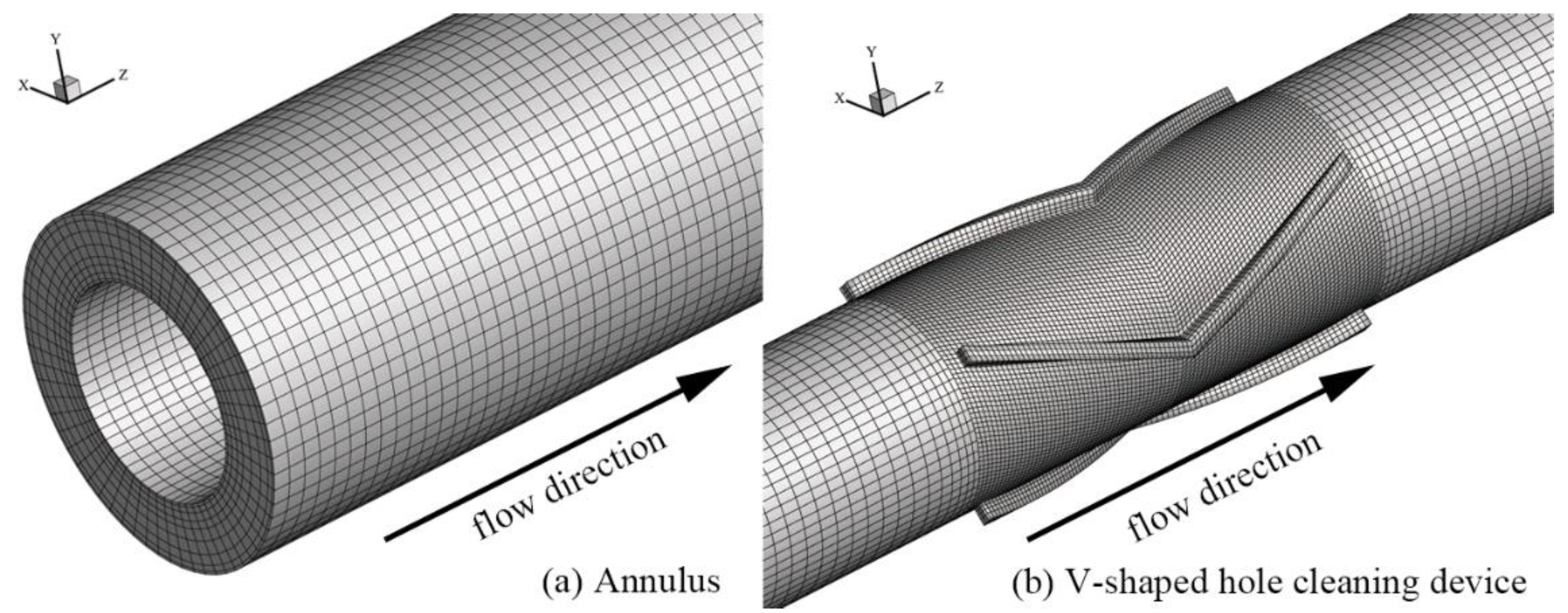
2.3. Grid Division and Independence

In this study, the geometry of the V-shaped hole cleaning device meshed in a structured grid. Structured hexahedral grids were generated in the entire domain of the annulus, as shown in Figure 2.
We conducted a mesh independent analysis of the V-shaped hole cleaning device with 522,100, 784,950, 1,036,950, and 1,396,200 hexahedral grids. The difference in pressure drops between 522,100 and 784,950 hexahedral grids was about 6.21%, and the difference in pressure drop between 784,950 and 1,036,950 hexahedral nodes was less than 0.5% (as shown in Table 2). The grids with 1,036,950 hexahedral grids produced grid-independent results as per the accuracy selected to balance computational cost and accuracy.
Error was used to check the precision of the calculation method for different grid sizes:
error = | Δ p Δ p finest   mesh Δ p finest   mesh | × 100 %

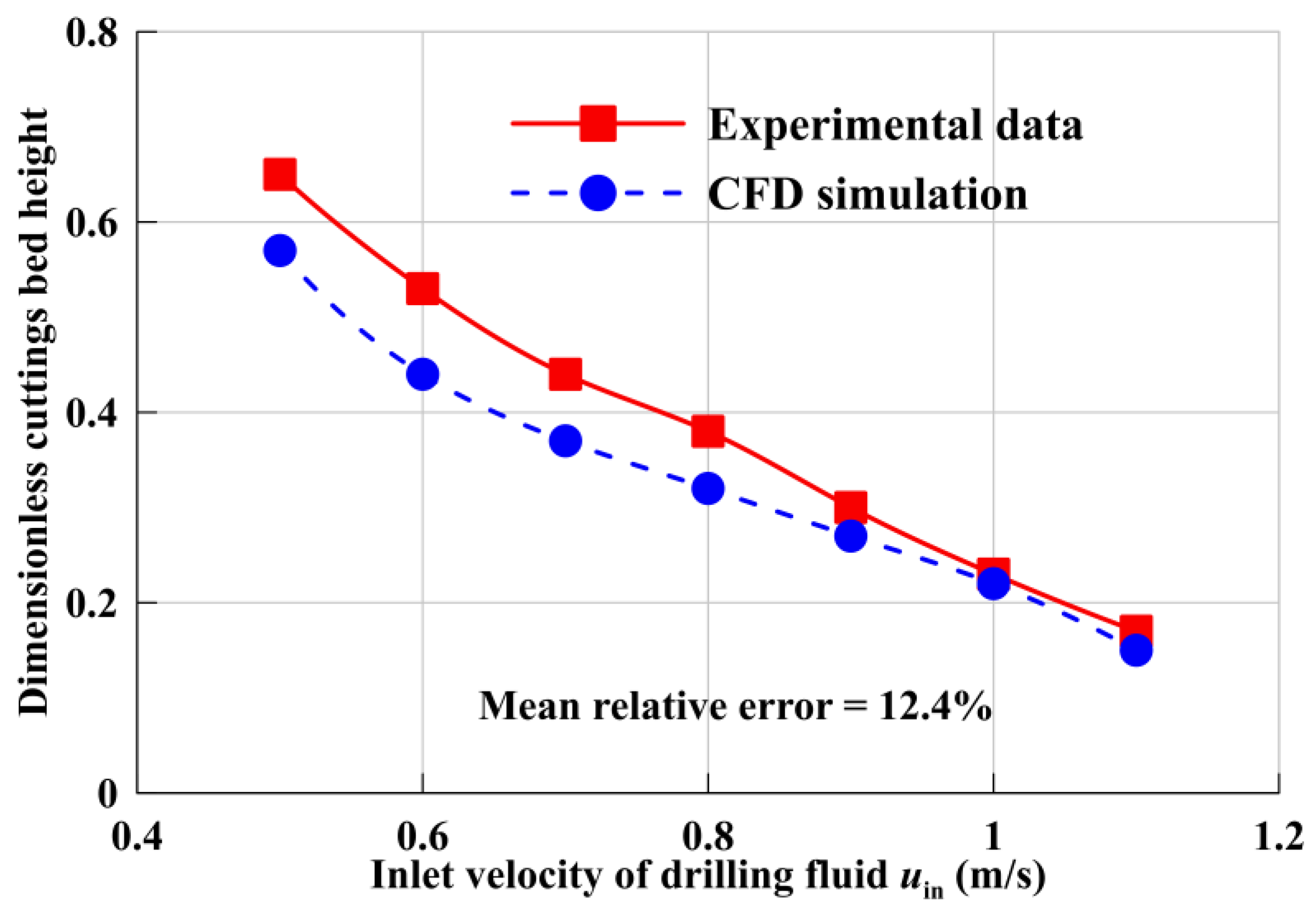
2.4. CFD Verification

The simulated and experimental cuttings bed height of annulus were compared as shown in Figure 3. The simulated cuttings bed height was calculated based on the borehole geometric parameters and annular cuttings concentration. The two sets of data were generally in good agreement; this shows good CFD predictions of the hole cleaning performance using the Eulerian–Eulerian TFM model.
The Mean relative error was calculated as follows:
mean   relative   error = 1 N i = 1 N | h num h exp h exp | × 100 %
where N is the total number, hnum represents numerical result of cuttings bed height, and hexp represents the experimental result of the cuttings bed height.

3. Results and Discussion

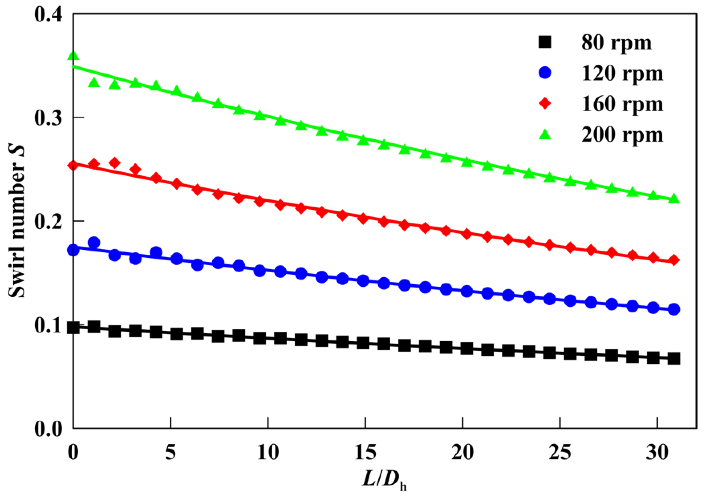
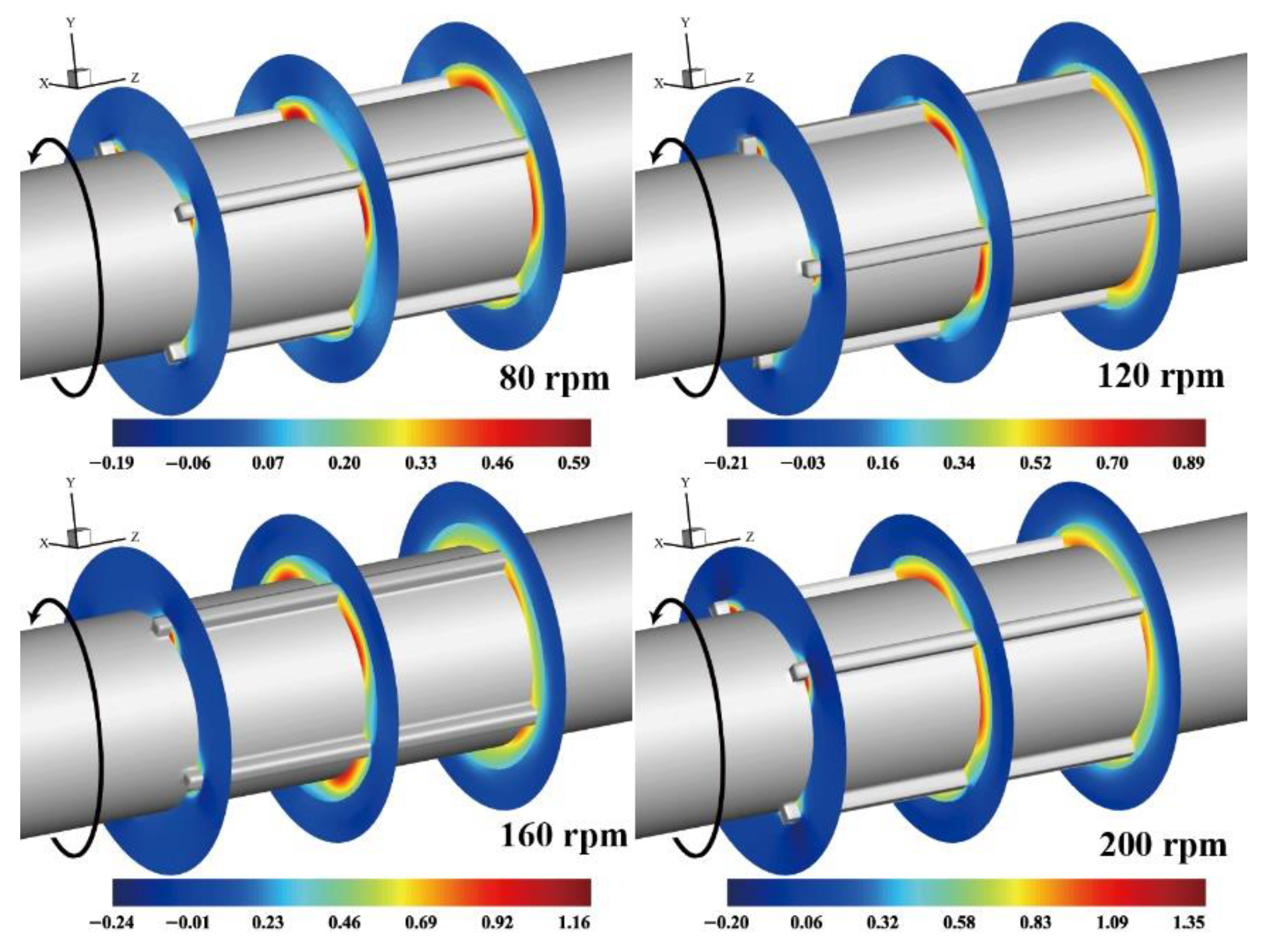
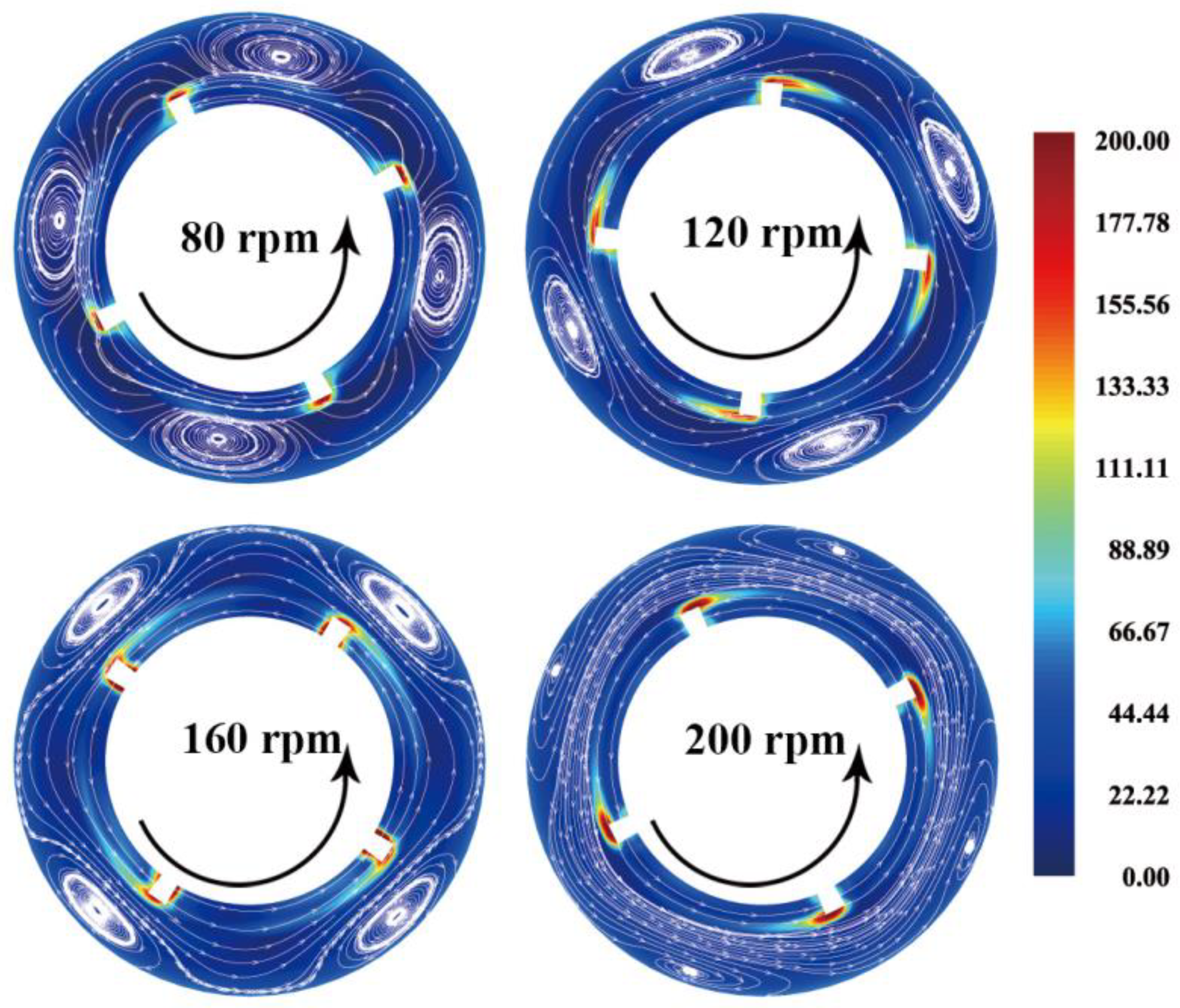
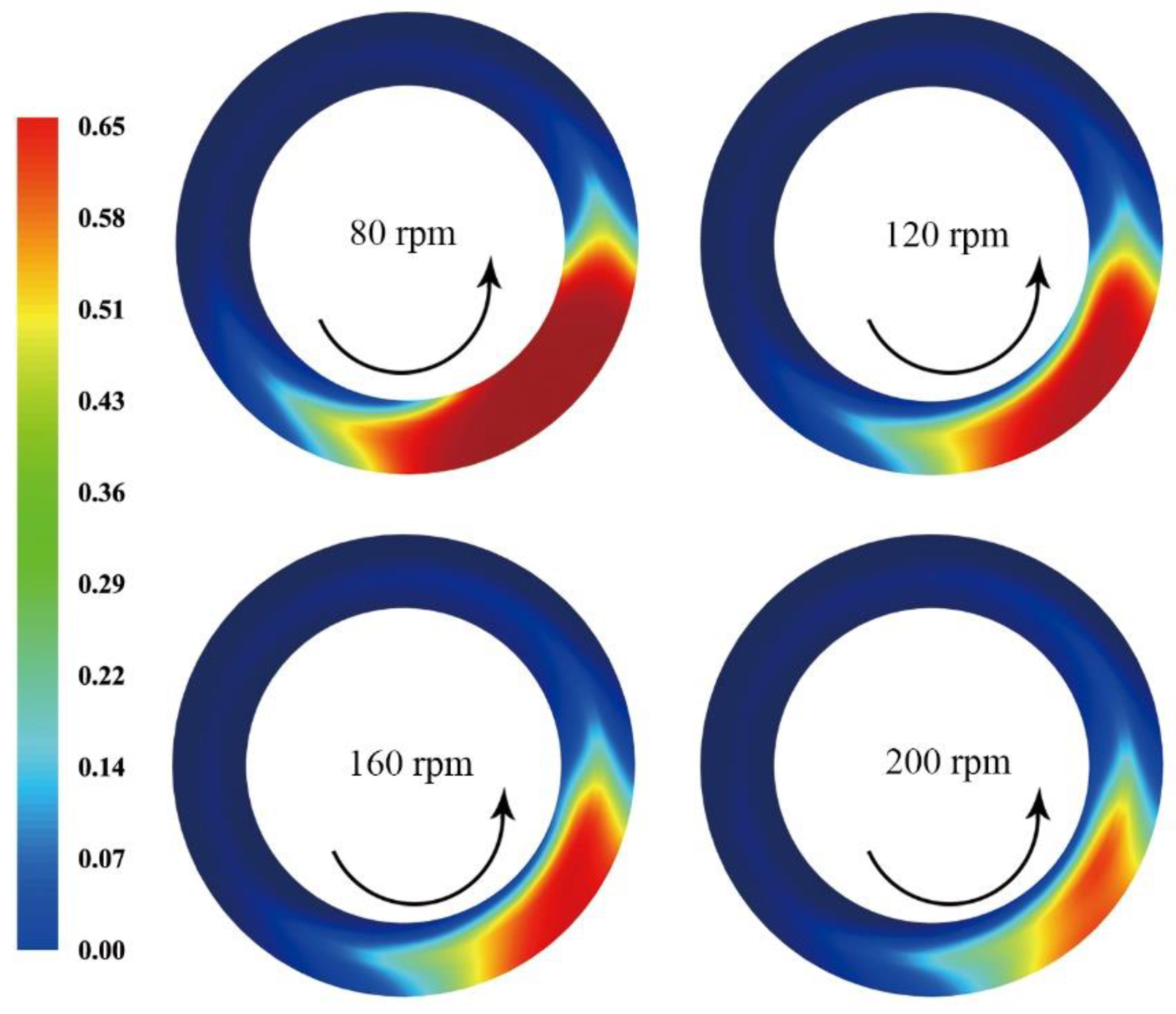
3.1. Effects of the Rotational Speed

The decay law of swirl intensity of spiral flow induced by the hole cleaning device (α = 0°) is shown in Figure 4 under four different speeds, and the decay equation was obtained by fitting and regression displayed in Table 3. Swirl intensity was used to characterize the swirl intensity in the spiral flow field, also known as swirl number S, which is defined as follows [12,25]:
S = 0 R u w ρ 1 r 2 d r R 0 R u 2 ρ 1 r d r
where u is the axial velocity and w is the circumferential velocity.
In the process of blade rotation, the spiral flow decays following the exponential law [26,27,28], and its decay equation is expressed as follows:
S = S 0 e β L / D h
where S0 is the swirl intensity at the end section of the blade, that is, the initial swirl intensity; β is the decay coefficient; L is the distance; and Dh is the hydraulic diameter.
The initial swirl intensity S0 increases as the rotational speed increases. When the rotational speed is 200 rpm, the initial swirl intensity S0 = 0.361, which is 3.72 times that of 80 rpm, but the increasing rate gradually slows down at a high rotational speed. For example, at 80, 120, and 160 rpm, the increasing values of the initial swirl intensity S0 are 0.075, 0.082, and 0.107, respectively, for each 40 rpm increase in rotational speed. The decay coefficient of spiral flow is more significant when the rotational speed is more considerable. The research results show that the decay coefficient at 200 rpm is about 41.6% higher than that of a rotational speed at 80 rpm, as shown in Table 3. The reason for this is that the energy loss caused by wall friction and fluid viscosity is also significant at a high rotational speed.
Figure 5 shows the time-averaged fluid’s circumferential velocity distribution under different rotational speeds. The circumferential velocity of the fluid behind the suction surface of the blade is large under the action of a rotation. The circumferential velocity intensity and distribution range of fluid increase with the rotational speed increase. The maximum tangential velocity exceeds 1.35 m/s as the rotational speed is 200 rpm. The main principle of the hole cleaning device is to reduce the thickness of the cuttings bed and to transfer cuttings to the high side of the wellbore by stirring and shearing the cuttings bed at the low side of the wellbore. At the same time, due to the unique design of the spiral structure, an upward eddy current will be generated locally during rotation to drive cuttings to transport upward, gradually transport to the inclined section to return to the wellhead smoothly.
Figure 6 shows the time-averaged vorticity and streamline distribution of the hole cleaning device (α = 0°) under four different rotational speeds. A vortex opposite to the direction of blade rotation under the action of blade rotation, namely the tip leakage vortex, will appear near the wellbore behind the suction surface due to the fluid leakage through the tip clearance under the action of the pressure difference between the pressure surface and the suction surface. The tangential kinetic energy in the spiral flow’s main flow area increases with the rotational speed, and the tip leakage vortex gradually moves to the outside. The main flow’s absorption capacity increases, making the distribution area of the tip leakage vortex smaller.
Next, the time-averaged annular cuttings concentration contour was obtained, as shown in Figure 7. With the continuous flow of solid–liquid two phases of cuttings drilling fluid in the annulus, cuttings transportation can be gradually divided into three flow patterns, namely the cuttings suspension zone, the moving bed zone, and the fixed bed zone. The cuttings concentration in the annulus decreases significantly with the gradual increase in rotational speed. The blade rotation will change the circumferential flow of cuttings-drilling two-phase flow, which will change the distribution form of cuttings and make the cuttings bed swing. A higher cuttings bed height can be seen on one side compared with the other side, but on the whole, the area of the cuttings bed continues to decrease.

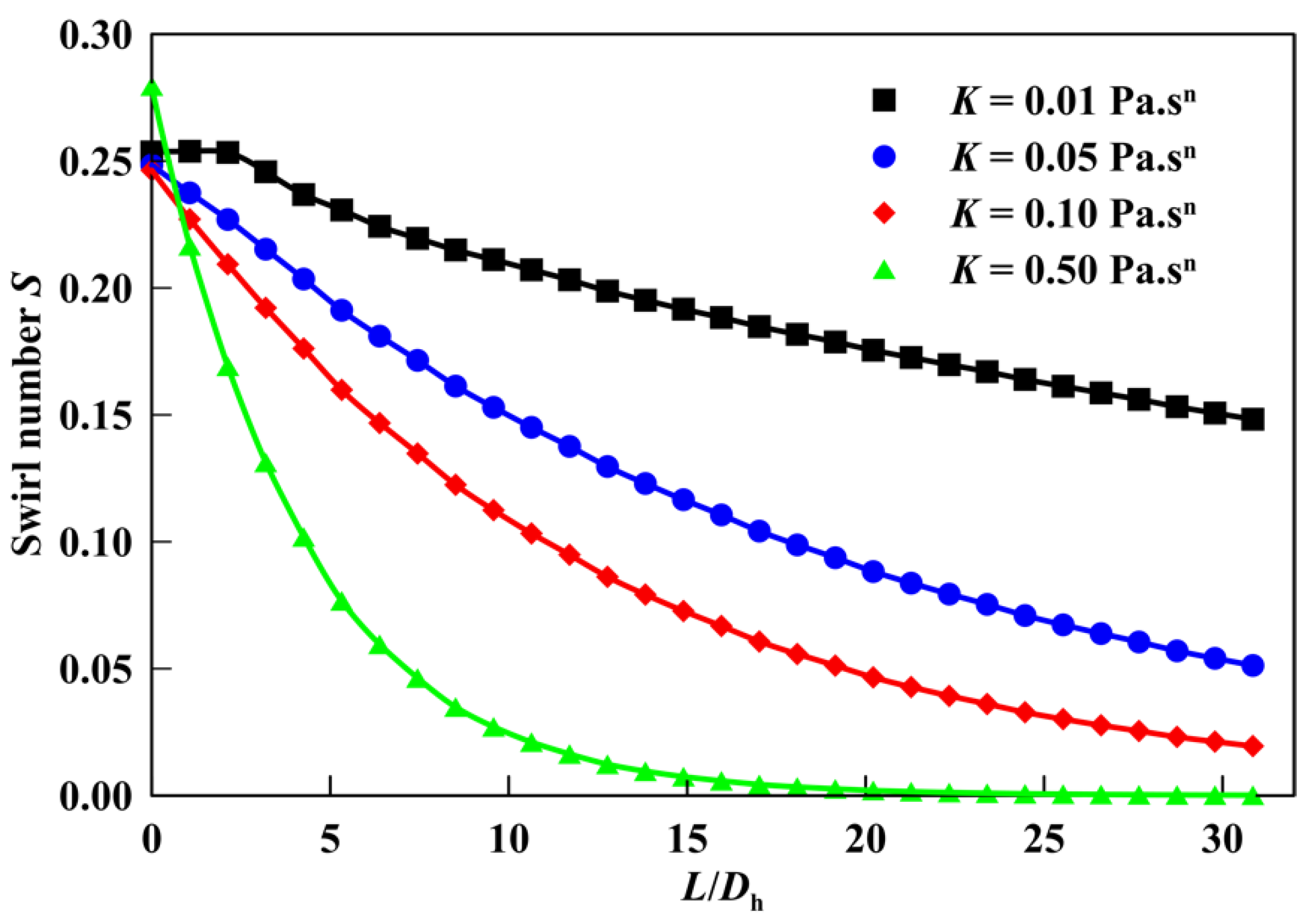
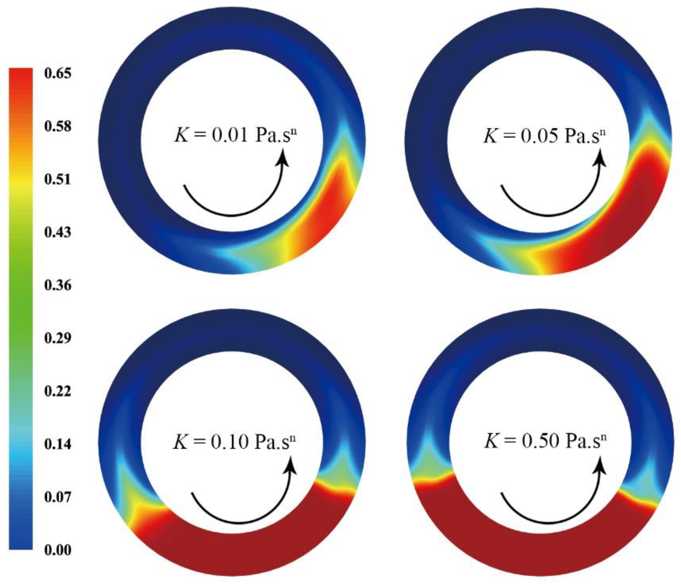
3.2. Effects of Consistency Coefficient of Drilling Fluid

The rheology of drilling fluid will also have a significant impact on the decay behavior of the blade-induced spiral flow. Therefore, the decay law of swirl intensity of spiral flow induced by the hole cleaning device (α = 0°) along the flow direction under four different fluid consistency coefficients (flow index n = 0.7) is shown in Figure 8, and the decay equation is obtained by fitting and regression displayed in Table 4. The initial swirl intensity S0 changes a little with different consistency coefficients, and the main difference is the decay coefficient β. In other words, the continuity distance of spiral flow is different, which indicates that the greater the consistency coefficient of drilling fluid, the faster the decay coefficient of blade induced spiral flow, the shorter the effective action distance of the hole cleaning device, and the worse the hole cleaning effect.
Figure 9 shows the time-averaged, annular cuttings concentration contour under four different fluid consistency coefficients. The erosion phenomenon of cuttings bed gradually weakens with the increase in fluid consistency coefficient. The blade-induced spiral flow will decay rapidly in the drilling fluid with a significant consistency coefficient, making it difficult for the drilling fluid to obtain the ability for suspended cuttings continuously. For low viscosity drilling fluid, the spiral flow induced by the rotation of the hole cleaning device can have a smaller decay coefficient; that is, there is a longer swirl duration. Therefore, using a V-shaped hole cleaning device may not achieve a good hole cleaning effect when selecting drilling fluid with a significant consistency coefficient in horizontal well drilling.

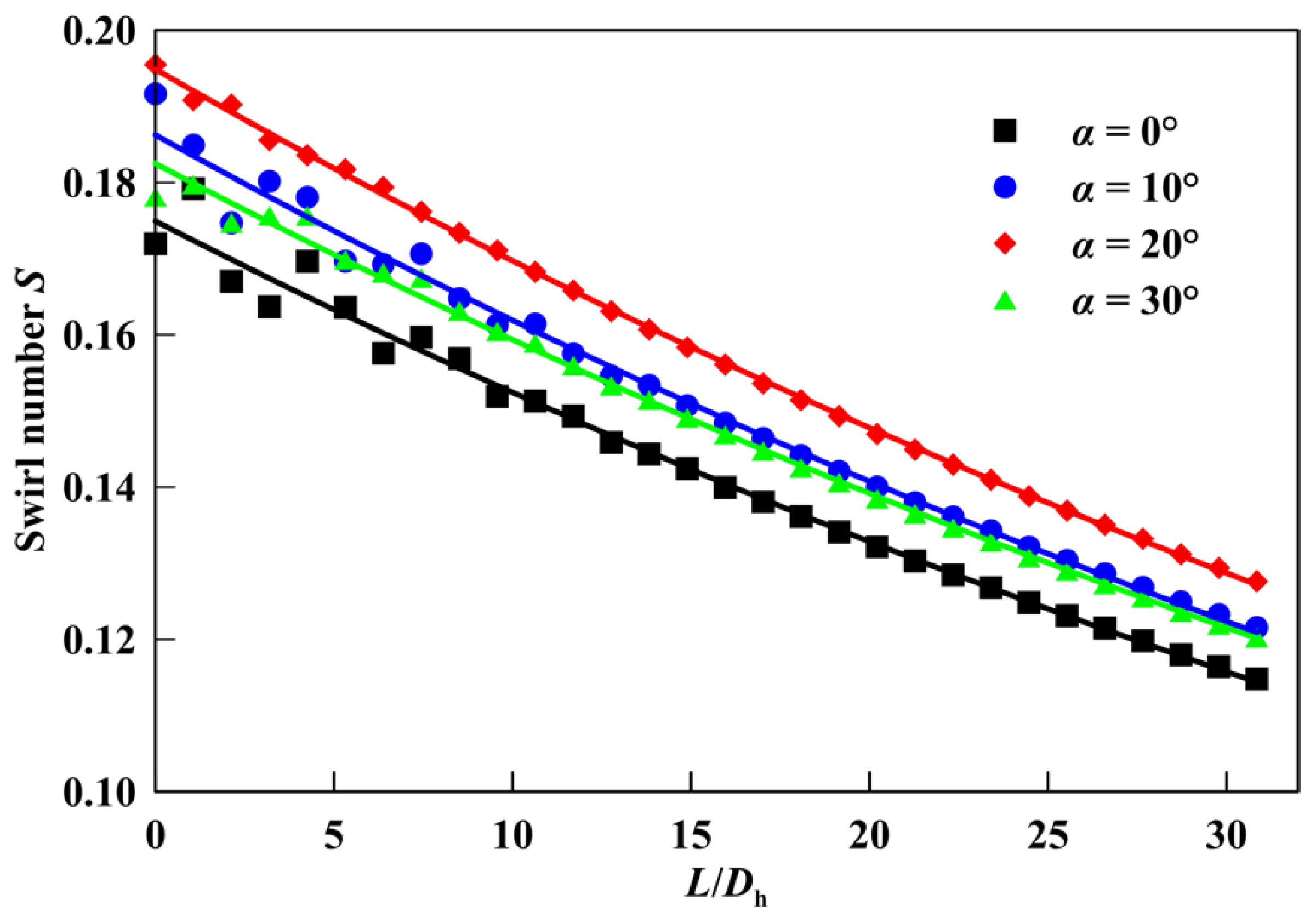
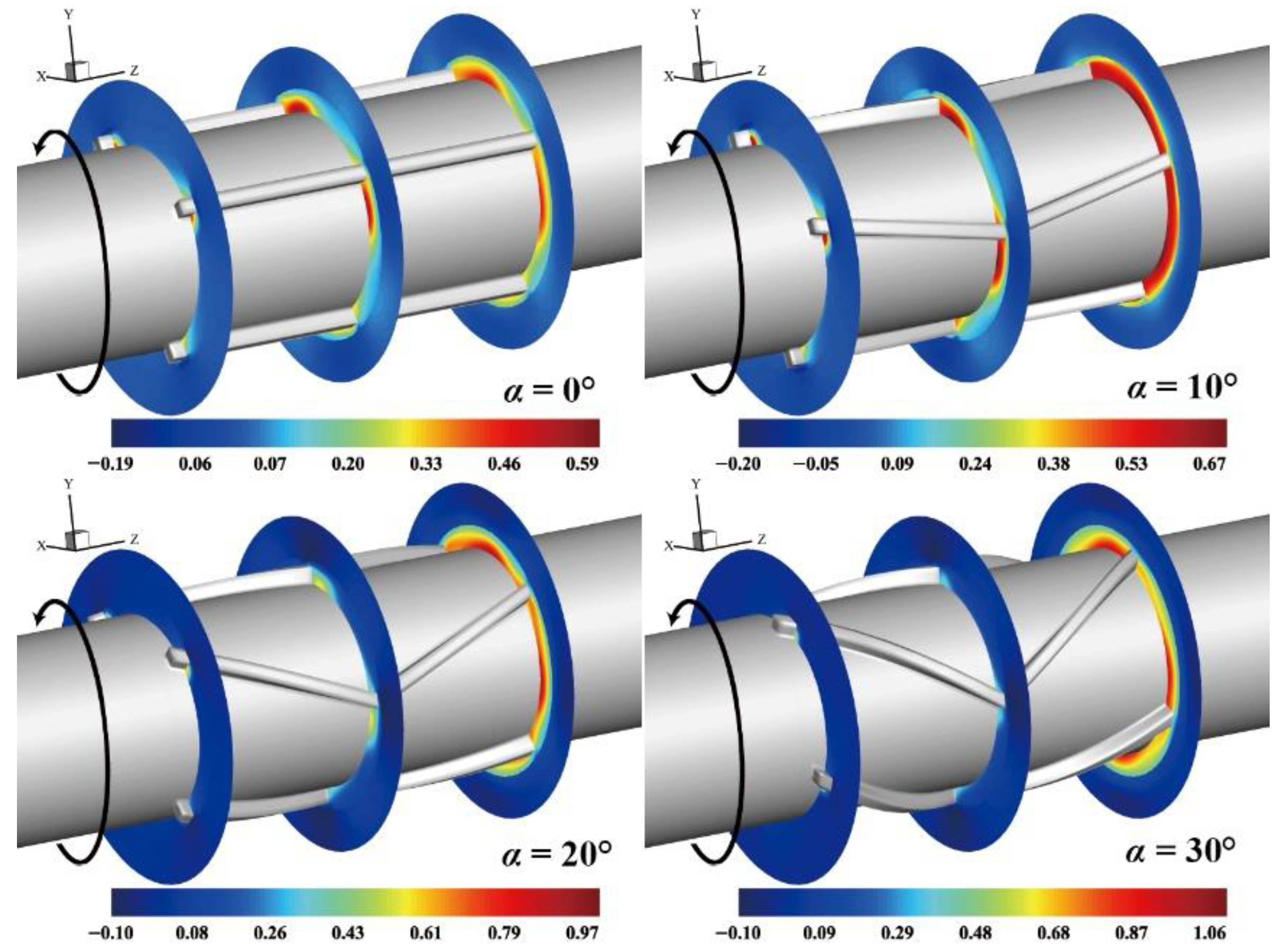
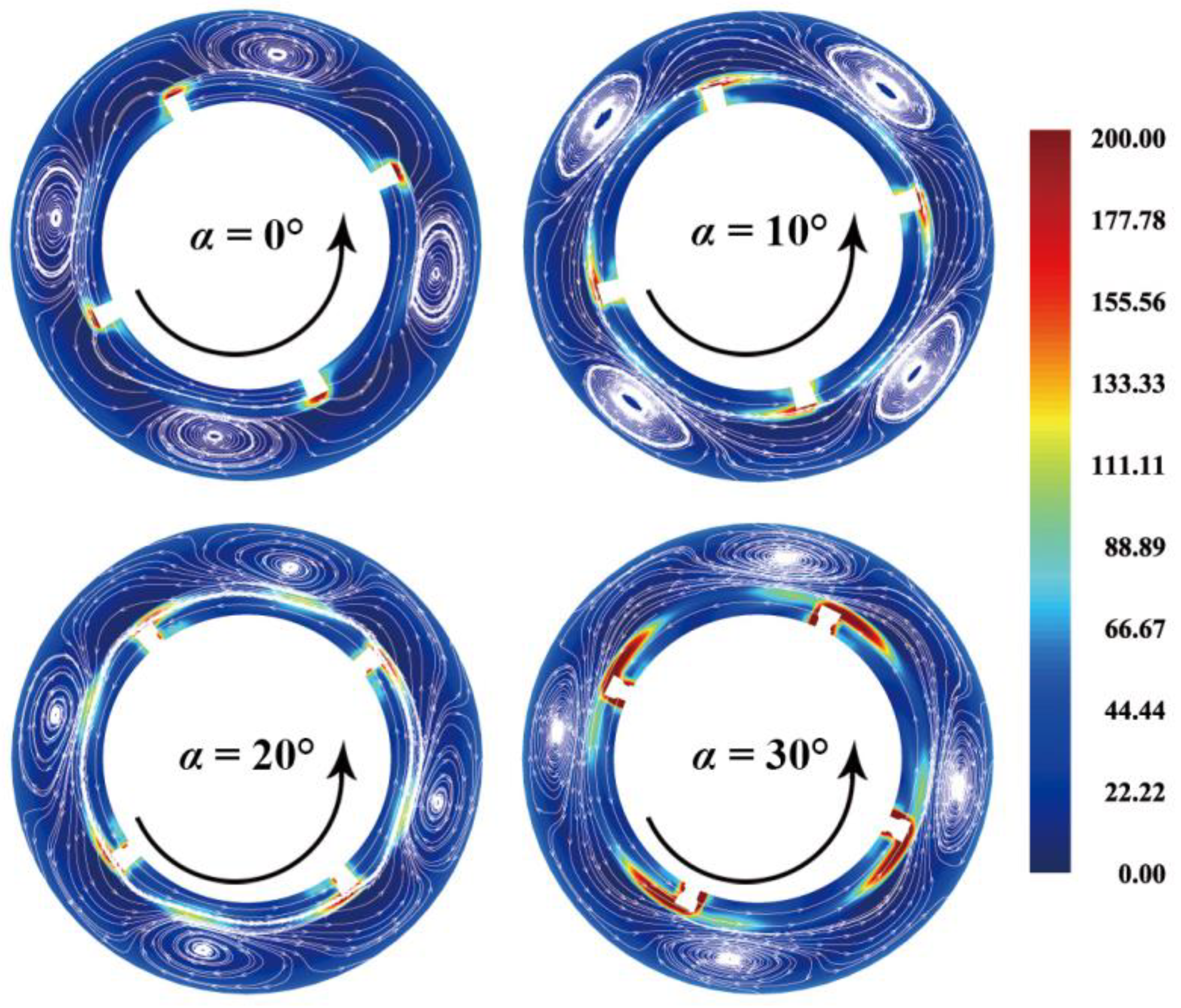
3.3. Effects of the Helix Angle of V-Shaped Hole Cleaning Device

The swirl intensity decay law of spiral flow induced by the V-shaped hole cleaning device (α = 0°) along the flow direction under four different helix angles is shown in Figure 10, and the decay equation is obtained by fitting and regression, as displayed in Table 5. It can be seen that when the helix angle increases from α = 0° to α = 30°, the change in the initial swirl intensity S0 is not noticeable, which is concentrated in the range of S0 = 0.172~0.195. When the helix angle is near α = 20°, the blade has the most robust ability to induce spiral flow. The change of helix angle will deflect the flow direction of the local fluid. After the fluid flows through the blade, the flow is deflected by the deflection force of the rotational blade, so that the spiral flow with apparent circumferential velocity distribution is induced locally to improve the local hole cleaning effect.
When the rotational speed is 120 rpm, the time-averaged fluid’s circumferential velocity distribution of the V-shaped blade under different helix angles is shown in Figure 11. It can be seen that with the increase in helix angle, the intensity and range of circumferential velocity induced by the V-shaped blade increase. The blade-induced ability was better when the helix angle was from about 10 to 20 degrees.
The time-averaged vorticity and streamline distribution at the end cross-section of the V-shaped blade under different helix angles are shown in Figure 12. It can be seen that the ability of the V-shaped blade to induce swirl increases with the increase in helix angle and the influence range of tip leakage vortex gradually decreases. The area occupied by tip leakage vortex in the center of flow channel decreases gradually with the increase in helix angle, and spiral flow is dominant.
The time-averaged annular cuttings concentration contour with different helix angle conditions is shown in Figure 13. The cuttings bed swings significantly in the circumferential direction, and the cuttings deposited on the low side of the annulus can transport from narrow gap to wide gap and transport to the wellhead driven by axial flowing drilling fluid, which significantly improves the hole cleaning performance in the annulus. However, with the increase in helix angle, the change in cuttings bed area in the annulus is not apparent. The hole cleaning performance is the strongest when the helix angle is near α = 20°, and the hole cleaning performance is the second strongest when α = 10°.

3.4. Evaluation of the Effective Action Distance of V-Shaped Hole Cleaning Device

The effective action distance under the rotation of the V-shaped hole cleaning device in the experiment is shown in Figure 14. It can be seen that after a certain distance behind the hole cleaning device, there are cuttings bed accumulation in the annulus. The cuttings can be suspended in the annulus within a distance behind the device due to the spiral flow induced by the hole cleaning device. The spiral flow continues to decay, making it difficult for the particles to maintain the suspended state and to begin to settle and form a cuttings bed along the flow direction. Finally, the cuttings bed height increases to a stable state.
As shown in Figure 15, the V-shaped hole cleaning device with helix angle α = 20° was selected and placed on the drill pipe of the flow loop to conduct hole cleaning experimental research and to compare it with the numerical simulation results. The effective action distance of the V-shaped blade increases as the rotational speed increases. According to the simulation results, when the speed reaches the maximum (200 rpm), the effective action distance can reach 1.8 m, slightly higher than the experimental results. When the rotating speed is between 160 rpm and 200 rpm, the increment of the effective action distance is more significant than when the rotational speed is low. The comparison between our numerical results and experimental data shows that the Eulerian–Eulerian TFM model is suitable for the numerical simulation of solid–liquid two-phase flow in the annulus and can obtain high prediction accuracy.

4. Conclusions

In this study, the decay behavior and hole cleaning effect of spiral flow induced by the V-shaped hole cleaning device in horizontal wells have been investigated by means of experiments and numerical simulations. Additionally, the effects of blade rotational speeds, fluid consistency coefficient, and blade helix angles on the hole cleaning effect are studied through numerical simulation. From the measured results, it is found that the initial swirl intensity increases as the rotational speed increases. The hole cleaning performance was better when the helix angle was from about 10 to 20 degrees. Increasing the fluid consistency coefficient will rapidly make the spiral flow decay, resulting in a shorter effective action distance and a worse hole cleaning effect. A comparison of the numerical results with experimental data shows that the Eulerian–Eulerian TFM model is suitable for numerical simulation of solid–liquid two-phase flow in the annulus.

Author Contributions

Conceptualization, Y.Z. and G.J.; Methodology, Y.H.; Validation, Z.L.; Writing—review and editing, G.J. All authors have read and agreed to the published version of the manuscript.

Funding

This research was funded by Southern Marine Science and Engineering Guangdong Laboratory (Zhanjiang) (grant No. ZJW-2019-03) and the National Natural Science Foundation of China (grant No. 52004064).

Conflicts of Interest

The authors declare no conflict of interest.

References

  1. Heydari, O.; Sahraei, E.; Skalle, P. Investigating the impact of drillpipe’s rotation and eccentricity on cuttings transport phenomenon in various horizontal annuluses using computational fluid dynamics (CFD). J. Pet. Sci. Eng. 2017, 156, 801–813. [Google Scholar] [CrossRef]
  2. Sayindla, S.; Lund, B.; Ytrehus, J.D.; Saasen, A. Hole-cleaning performance comparison of oil-based and water-based drilling fluids. J. Pet. Sci. Eng. 2017, 159, 49–57. [Google Scholar] [CrossRef] [Green Version]
  3. Yeu, W.J.; Katende, A.; Sagala, F.; Ismail, I. Improving hole cleaning using low density polyethylene beads at different mud circulation rates in different hole angles. J. Nat. Gas Sci. Eng. 2019, 61, 333–343. [Google Scholar] [CrossRef]
  4. Heshamudin, N.S.; Katende, A.; Rashid, H.A.; Ismail, I.; Sagala, F.; Samsuri, A. Experimental investigation of the effect of drill pipe rotation on improving hole cleaning using water-based mud enriched with polypropylene beads in vertical and horizontal wellbores. J. Pet. Sci. Eng. 2019, 179, 1173–1185. [Google Scholar] [CrossRef]
  5. Boyou, N.V.; Ismail, I.; Wan Sulaiman, W.R.; Sharifi Haddad, A.; Husein, N.; Hui, H.T.; Nadaraja, K. Experimental investigation of hole cleaning in directional drilling by using nano-enhanced water-based drilling fluids. J. Pet. Sci. Eng. 2019, 176, 220–231. [Google Scholar] [CrossRef] [Green Version]
  6. Pang, B.; Wang, S.; Liu, G.; Jiang, X.; Lu, H.; Li, Z. Numerical prediction of flow behavior of cuttings carried by Herschel-Bulkley fluids in horizontal well using kinetic theory of granular flow. Powder Technol. 2018, 329, 386–398. [Google Scholar] [CrossRef]
  7. Epelle, E.I.; Gerogiorgis, D.I. A multiparametric CFD analysis of multiphase annular flows for oil and gas drilling applications. Comput. Chem. Eng. 2017, 106, 645–661. [Google Scholar] [CrossRef] [Green Version]
  8. Zhu, X.H.; Sun, C.; Tong, H. Distribution features, transport mechanism and destruction of cuttings bed in horizontal well. J. Hydrodyn. 2013, 25, 628–638. [Google Scholar] [CrossRef]
  9. Wilson, A. Innovative Tool Improves Hole-Cleaning Efficiency in Extended-Reach Wells. J. Pet. Technol. 2016, 68, 80–82. [Google Scholar] [CrossRef]
  10. Vanpuymbroeck, L.; Drilling, V.A.M. Increasing Drilling Performance Using Hydro-Mechanical Hole Cleaning Devices. In SPE Unconventional Gas Conference and Exhibition; OnePetro: Richardson, TX, USA, 2013. [Google Scholar]
  11. Ahmed, R.; Sagheer, M.; Takach, N.; Majidi, R.; Yu, M.; Miska, S.; Rohart, C.; Boulet, J. Experimental Studies on the Effect of Mechanical Cleaning Devices on Annular Cuttings Concentration and Applications for Optimizing ERD Systems. In SPE Annual Technical Conference and Exhibition; OnePetro: Richardson, TX, USA, 2010. [Google Scholar] [CrossRef]
  12. Qu, J.; Yan, T.; Sun, X.; Li, Z.; Li, W. Decaying swirl flow and particle behavior through the hole cleaning device for horizontal drilling of fossil fuel. Energies 2019, 12, 336. [Google Scholar] [CrossRef] [Green Version]
  13. Yan, T.; Qu, J.; Sun, X.; Li, Z.; Li, W. Investigation on horizontal and deviated wellbore cleanout by hole cleaning device using CFD approach. Energy Sci. Eng. 2019, 7, 1292–1305. [Google Scholar] [CrossRef] [Green Version]
  14. Yan, T.; Qu, J.; Sun, X.; Chen, Y.; Hu, Q.; Li, W.; Zhang, H. Numerical investigation on horizontal wellbore hole cleaning with a four-lobed drill pipe using CFD-DEM method. Powder Technol. 2020, 375, 249–261. [Google Scholar] [CrossRef]
  15. Movahedi, H.; Vasheghani Farahani, M.; Jamshidi, S. Application of Hydrated Basil Seeds (HBS) as the herbal fiber on hole cleaning and filtration control. J. Pet. Sci. Eng. 2017, 152, 212–228. [Google Scholar] [CrossRef]
  16. Movahedi, H.; Shad, S.; Mokhtari-Hosseini, Z.B. Modeling and simulation of barite deposition in an annulus space of a well using CFD. J. Pet. Sci. Eng. 2018, 161, 476–496. [Google Scholar] [CrossRef]
  17. Zeneli, M.; Nikolopoulos, A.; Nikolopoulos, N.; Grammelis, P.; Karellas, S.; Kakaras, E. Simulation of the reacting flow within a pilot scale calciner by means of a three phase TFM model. Fuel Process. Technol. 2017, 162, 105–125. [Google Scholar] [CrossRef]
  18. Xia, Z.; Fan, Y.; Wang, T.; Guo, X.; Chen, C. A TFM-KTGF jetting fluidized bed coal gasification model and its validations with data of a bench-scale gasifier. Chem. Eng. Sci. 2015, 131, 12–21. [Google Scholar] [CrossRef]
  19. Hernández-Jiménez, F.; Sánchez-Prieto, J.; Cano-Pleite, E.; Soria-Verdugo, A. Lateral solids meso-mixing in pseudo-2D fluidized beds by means of TFM simulations. Powder Technol. 2018, 334, 183–191. [Google Scholar] [CrossRef]
  20. Huilin, L.; Gidaspow, D.; Bouillard, J.; Wentie, L. Hydrodynamic simulation of gas-solid flow in a riser using kinetic theory of granular flow. Chem. Eng. J. 2003, 95, 1–13. [Google Scholar] [CrossRef]
  21. Parsi, M.; Kara, M.; Agrawal, M.; Kesana, N.; Jatale, A.; Sharma, P.; Shirazi, S. CFD simulation of sand particle erosion under multiphase flow conditions. Wear 2017, 376–377, 1176–1184. [Google Scholar] [CrossRef]
  22. Kim, S. A novel design method of the dividing header configuration using 3D numerical simulation for a heat exchanger with a parallel arrangement. Appl. Therm. Eng. 2019, 159, 113807. [Google Scholar] [CrossRef]
  23. Chouaieb, S.; Kriaa, W.; Mhiri, H.; Bournot, P. Swirl generator effect on a confined coaxial jet characteristics. Int. J. Hydrogen Energy 2017, 42, 29014–29025. [Google Scholar] [CrossRef]
  24. Yan, T.; Qu, J.Y.; Sun, X.F.; Li, W.; Chen, Y.; Hu, Q.B. A novel predictive model of drag coefficient and settling velocity of drill cuttings in non-Newtonian drilling fluids. Pet. Sci. 2021, 18, 1729–1738. [Google Scholar] [CrossRef]
  25. Li, G.; Hall, P.; Miles, N.; Wu, T. Improving the efficiency of “Clean-In-Place” procedures using a four-lobed swirl pipe: A numerical investigation. Comput. Fluids 2015, 108, 116–128. [Google Scholar] [CrossRef]
  26. Li, G.; Miles, N.J.; Wu, T.; Hall, P. Large eddy simulation and Reynolds-averaged Navier–Stokes based modelling of geometrically induced swirl flows applied for the better understanding of Clean-In-Place procedures. Food Bioprod. Process. 2017, 104, 77–93. [Google Scholar] [CrossRef]
  27. Fokeer, S.; Lowndes, I.S.; Hargreaves, D.M. Numerical modelling of swirl flow induced by a three-lobed helical pipe. Chem. Eng. Process. Process Intensif. 2010, 49, 536–546. [Google Scholar] [CrossRef]
  28. Yan, T.; Qu, J.; Sun, X.; Chen, Y.; Hu, Q.; Li, W. Numerical evaluation on the decaying swirling flow in a multi-lobed swirl generator. Eng. Appl. Comput. Fluid Mech. 2020, 14, 1198–1214. [Google Scholar] [CrossRef]
Figure 1. Experimental flow loop used to evaluate hole cleaning effect of V-shaped hole cleaning device. (a) Front view of the drill pipe, (b) back view of the annulus.
Applsci 12 05141 g001
Figure 2. Grid representation of calculation region.
Applsci 12 05141 g002
Figure 3. Comparison between simulated and experimented cuttings bed height.
Applsci 12 05141 g003
Figure 4. Decay law of swirl intensity of spiral flow induced by the hole cleaning device (α = 0°) along the flow direction under different rotational speeds (numerical results).
Applsci 12 05141 g004
Figure 5. Fluid circumferential velocity distribution at different cross sections of the blade under different rotational speeds (α = 0°).
Applsci 12 05141 g005
Figure 6. Vorticity and streamline distribution of the hole cleaning device (α = 0°) under different rotational speeds.
Applsci 12 05141 g006
Figure 7. Annular cuttings concentration contour at different rotational speed conditions.
Applsci 12 05141 g007
Figure 8. Decay law of swirl intensity of spiral flow induced by the hole cleaning device (α = 0°) along the flow direction under different fluid consistency coefficients (numerical results).
Applsci 12 05141 g008
Figure 9. Annular cuttings concentration contour at different fluid consistency index conditions.
Applsci 12 05141 g009
Figure 10. Decay law of swirl intensity of spiral flow induced by the hole cleaning device along the flow direction under different helix angles (numerical results).
Applsci 12 05141 g010
Figure 11. Fluid circumferential velocity distribution at different cross sections of the blade under different helix angles.
Applsci 12 05141 g011
Figure 12. Vorticity and streamline distribution of the hole cleaning device under different helix angles.
Applsci 12 05141 g012
Figure 13. Annular cuttings concentration contour at different helix angle conditions.
Applsci 12 05141 g013
Figure 14. Experimental flow loop used to evaluate effective action distance (back view).
Applsci 12 05141 g014
Figure 15. Comparison between simulated and experimented effective action distance.
Applsci 12 05141 g015
Table 1. Detailed parameters used in simulations.
SymbolsPropertiesValuesUnits
D1Hole diameter120mm
D2Pipe diameter73mm
EEccentricity0-
ρlDensity of fluid1000kg/m3
ρsDensity of cuttings2500kg/m3
KConsistency index0.01/0.05/0.10/0.50Pa.sn
nFlow behavior index0.7-
ωRotational speed80/120/160/200rpm
dsDiameter of cuttings2mm
uinFluid inlet velocity0.5m/s
hHeight of blade5.75mm
NNumber of blades4-
αHelix angle of blade0; 10; 20; 30degree
Table 2. Sensitivity of grid size to simulation results.
Mesh NumbersPressure Drop (Pa/m)Error (%)
522,1001284.36.21%
784,9501363.20.45%
1,036,9501367.00.17%
1,396,2001369.3/
Table 3. Decay equation of spiral flow induced by the hole cleaning device (α = 0°) under different rotational speeds (numerical results).
Rotational Speed rpmDecay EquationInitial Swirl Intensity S0Decay Coefficient βR2
80 S n = 0.097 e 0.012 L / D h 0.0970.0120.993
120 S n = 0.172 e 0.013 L / D h 0.1720.0130.982
160 S n = 0.254 e 0.015 L / D h 0.2540.0150.990
200 S n = 0.361 e 0.017 L / D h 0.3610.0170.975
Table 4. Decay equation of spiral flow induced by the hole cleaning device (α = 0°) under different fluid consistency coefficients (numerical results).
Consistency Coefficient Pa.snDecay EquationInitial Swirl Intensity S0Decay Coefficient βR2
0.01 S n = 0.254 e 0.018 L / D h 0.2540.0180.992
0.05 S n = 0.248 e 0.051 L / D h 0.2480.0510.999
0.10 S n = 0.246 e 0.082 L / D h 0.2460.0820.999
0.50 S n = 0.280 e 0.241 L / D h 0.2800.2410.999
Table 5. Decay equation of spiral flow induced by the hole cleaning device under different helix angles (numerical results).
Helix Angle DegreeDecay EquationInitial Swirl Intensity S0Decay Coefficient βR2
0 S n = 0.172 e 0.013 L / D h 0.1720.0130.982
10 S n = 0.192 e 0.016 L / D h 0.1920.0160.976
20 S n = 0.195 e 0.014 L / D h 0.1950.0140.999
30 S n = 0.178 e 0.012 L / D h 0.1780.0120.984
Publisher’s Note: MDPI stays neutral with regard to jurisdictional claims in published maps and institutional affiliations.

