Abstract
Cross-calibration using an autocollimator and a polygon is the traditional method for calibrating a rotary encoder. These angles, which can be calibrated using this method, are limited by the pitch angle of the polygon, which is 15° for a 24-faced polygon. In this work, we propose a new shift-angle method using the same setup as the traditional method. However, the new method can measure smaller than the pitch angle of the polygon, which is the measurement limitation of the traditional method. The proposed method can calibrate every angle of the rotary encoder. In the experiment, we use an autocollimator and a 24-faced polygon to calibrate the SelfA rotary encoder to verify the proposed shift-angle method. The SelfA rotary encoder, which comprises one rotary encoder and 12 read heads, is calibrated using self-calibration. The difference between the calibration results obtained by applying these two methods to the same SelfA rotary encoder is smaller than ±0.1″.
1. Introduction
The angle standard is based on the circle closure principle: the sum of the angles of a full circle must be 2π. Therefore, the circle closure principle is widely used to calibrate many reference angle standards and working angle standards, such as angle gauges, polygons, and rotary encoders. Rotary encoders are widely used in laboratories and factories in the field of measurement and manufacturing. The angle errors of the rotary encoders affect the measurements and manufacturing quality. For the precise calibration of the rotary encoders, two methods are widely used: self-calibration and cross-calibration.
In self-calibration, it is unnecessary to use an external standard to calibrate rotary encoders [1]. The sensor heads and rotary encoders are installed inside a rotary table. The sensor heads read out the measured angles distributed at different angles corresponding to the rotary encoder. According to the circle closure principle, a rotary encoder can self-calibrate. Many self-calibration methods have been proposed. Masuda et al. [2] proposed a calibration rotary encoder system in which six read-heads were unevenly spaced around a rotary encoder to self-calibrate its accuracy. Probst et al. [3,4,5] developed an angle comparator that was constructed using one rotary encoder and 16 read-heads in which eight read-heads were uniformly distributed and eight read-heads were arranged pairs. In this system, a new method for self-calibration of divided circles calibrated the rotary encoders. In addition, Jiao et al. [6,7] indicated an optimization-based arrangement of reading heads for self-calibration. Watanabe et al. [8,9,10,11] developed the SelfA rotary encoder for calibrating rotary encoders. The SelfA encoder consists of a rotary encoder and several groups of sensor heads.
Cross-calibration is widely used to calibrate angle standards. With this method, an auxiliary reference angle standard is used in conjunction with an equation based on the circle closure principle. The angle errors of the reference angle standard and the calibrated angle standard can be measured simultaneously. Many studies have demonstrated that such measurements involve the use of a polygon as the reference angle standard. Pavlov et al. [12,13] proposed the four-sided polygon as the reference angle standard to calibrate the laser dynamic goniometer. Akgoz et al. [14] indicated the 36-sided optical polygon as the reference angle standard to calibrate the index table. Many previous studies have employed different-faced polygons, such as 12 faces, 24 faces, and 36 faces, as the reference angle standard to calibrate the rotary encoder [15,16,17,18,19,20]. However, this method has a measurement limitation in terms of the pitch angle of the polygon.
In this paper, we present a new shift-angle method for calibrating rotary encoders at every angle. The introduction section presents the related research papers and techniques. Next, the theory and configuration section describes the proposed shift-angle method, which can be used to calibrate angles smaller than the pitch angle of the polygon. In the experiment, an autocollimator and a 24-faced polygon are used to calibrate the SelfA rotary encoder that is equipped with a rotary encoder and multi-arranged sensor heads. The SelfA rotary encoder can be calibrated by using self-calibration. The experiment shows the difference between the results of self-calibration and the proposed shift-angle method for the same SelfA rotary encoder. The results indicate that the proposed shift-angle method is feasible and can be validated. Then, the uncertainty evaluation of the shift-angle method is analyzed. Finally, a discussion and conclusions are presented.
2. Theory and Configuration
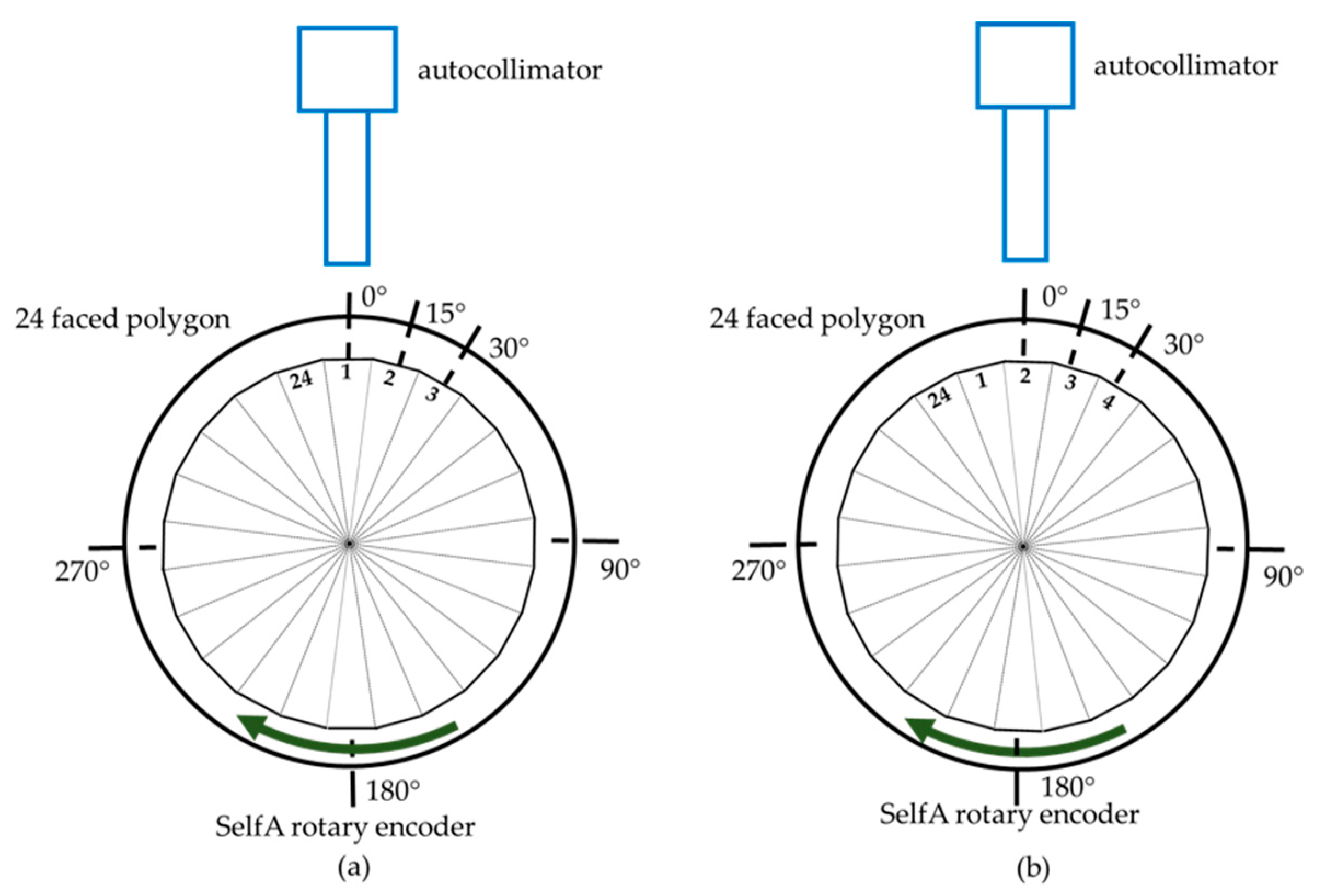
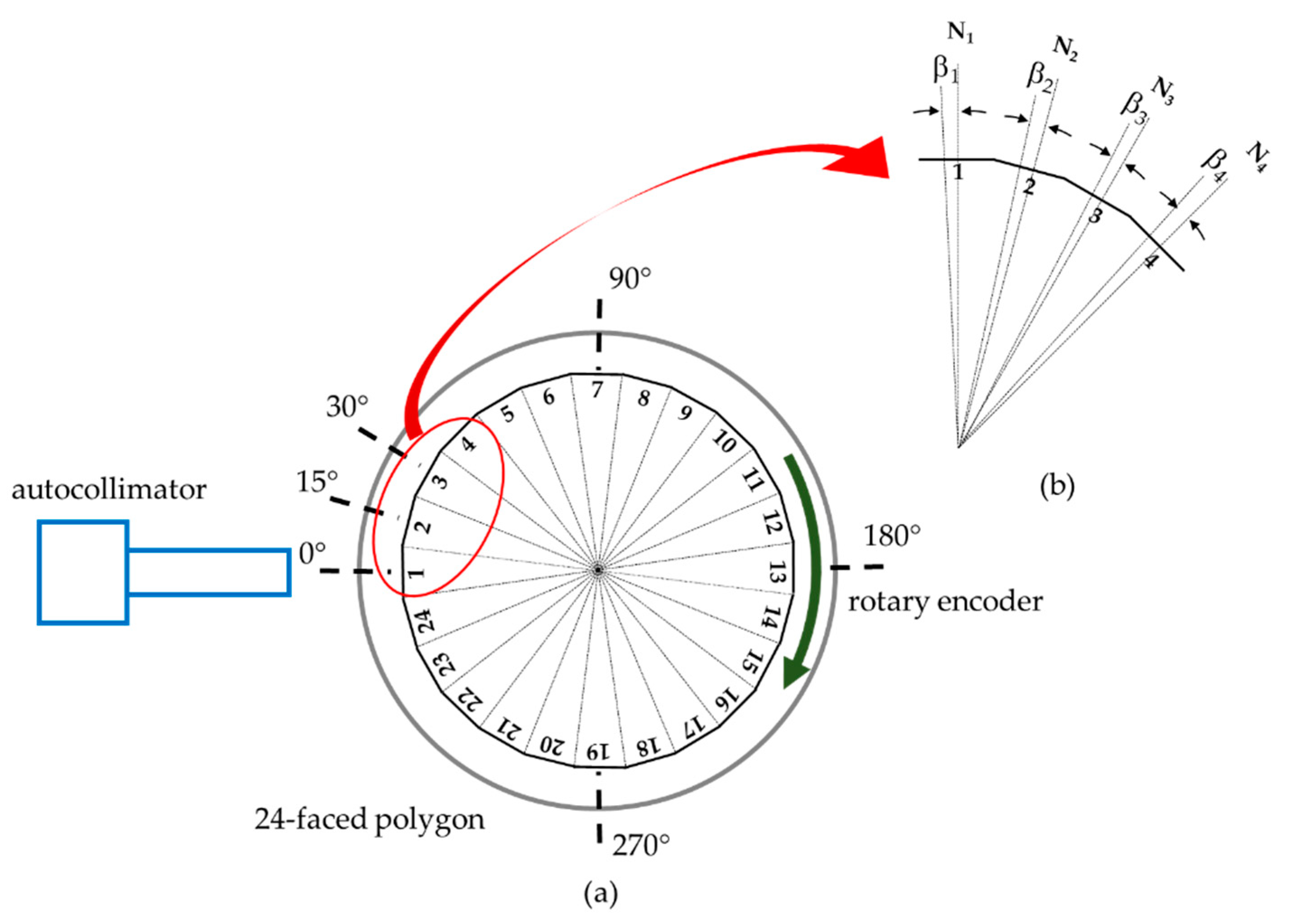
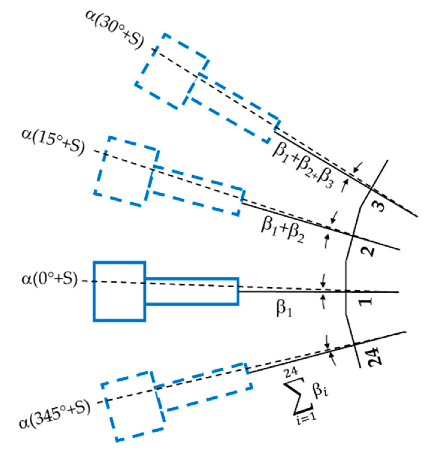
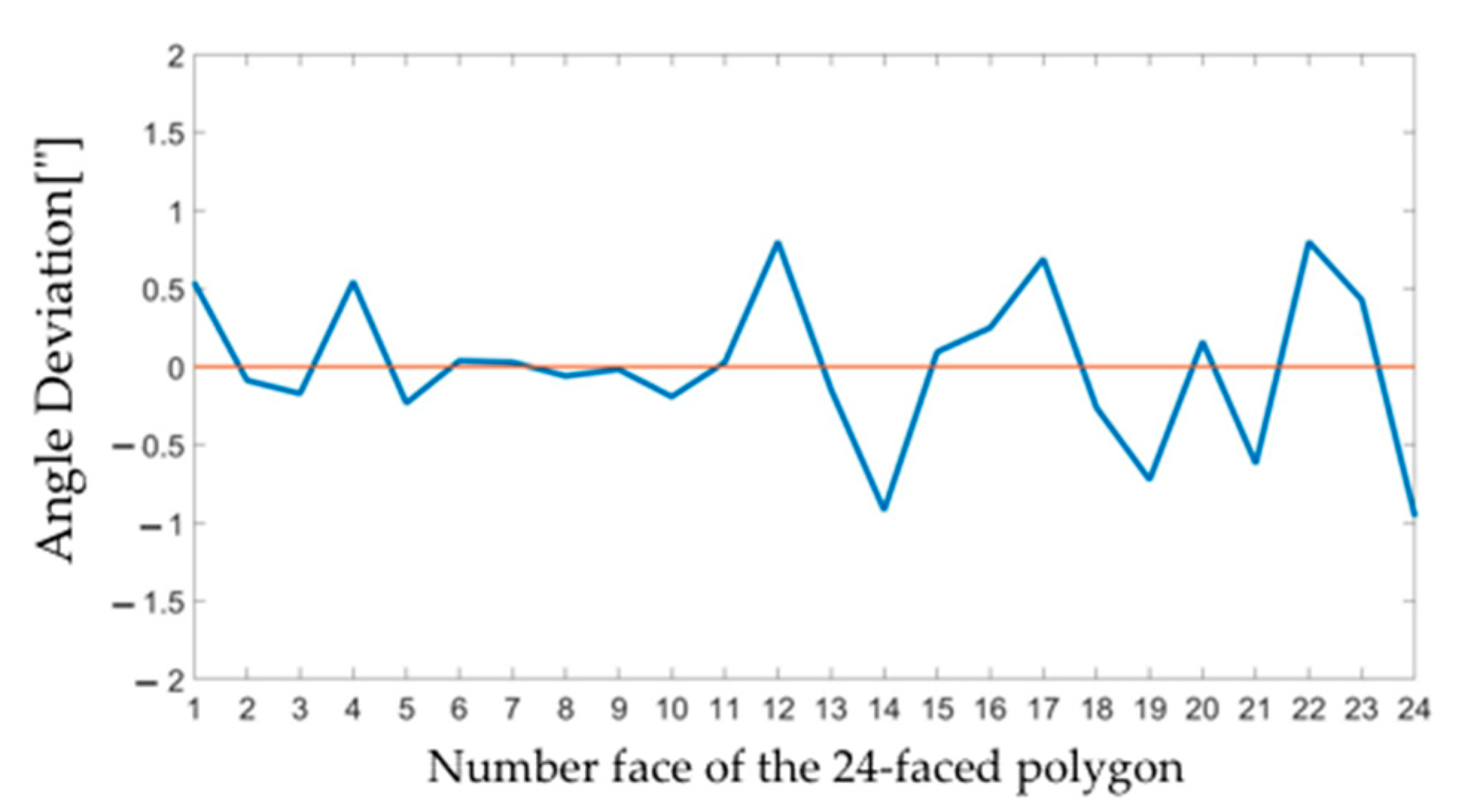
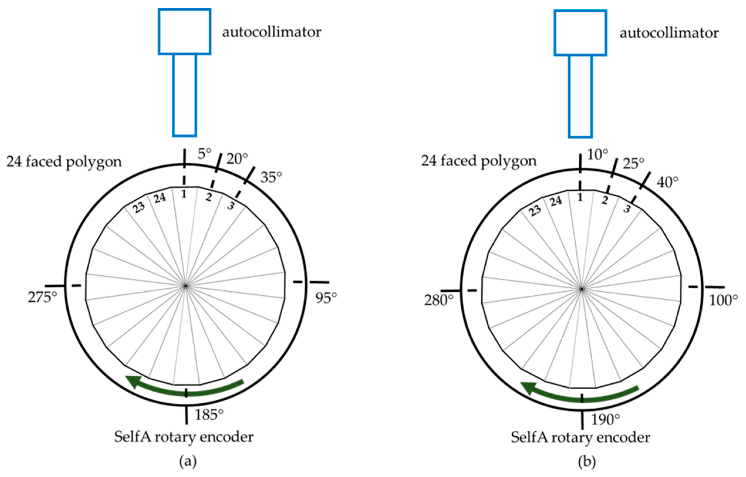
2.1. Shift-Angle Method for Polygon
Figure 1a shows a schematic of the calibration setup. An autocollimator is placed in front of a rotary encoder. A 24-faced polygon is mounted at the center of the rotary encoder. The 24-faced polygon is used in this study to illustrate the related theory and to conduct experiments [15]. A polygon with any number of faces can be used in practice. The polygon has 24 reflecting faces as the measuring faces. The autocollimator is aligned and collimated to reflect the faces of the polygon.
Figure 1.
(a) Diagram of the 24-faced polygon. (b) Enlarged view of the red circle highlighted in (a).
In the ideal polygon, the measuring faces are the same as the nominal faces. The measuring face (R) and the nominal face (N) are slightly tilted with respect to each other, as indicated in Figure 1b. For the 24-faced polygon, it is assumed that one full circle is divided into 24 nominal faces. The angle interval between two consecutive nominal faces is 15°, which is called the nominal pitch angle. The pitch angle deviation βi is the difference between the angle values of two adjacent measuring faces and the nominal pitch angle of 15°. Each measuring face has a different pitch angle deviation. Therefore, in our case, the 24-faced polygon exhibits 24 angle deviations. According to the circle closure principle, the summation of all the angle deviations must be zero.
The rotary encoder is calibrated to determine the angle error α (θ), which is the angle deviation between the measured and true angles. As illustrated in Figure 2, the angle error α (θ + S) is the angle error of the rotary encoder at (θ + S)°, where S is the shift-angle. Traditionally, the 24-faced polygon can be used to measure rotary encoder angles θ of 0°, 15°, …, 345° in steps of 15°. In contrast, with the proposed shift-angle method, rotary encoder angles of 0° + S, 15° + S, …, 345° + S in steps of 15° can be measured. According to the circle closure principle, the summation of the angle errors α (θ + S) for a full circle must be zero:
Figure 2.
Schematic of the calibration value determination.
The angle error of the rotary encoder cannot be measured directly by using an autocollimator and a polygon, because the measured values using an autocollimator contain the angle error of the rotary encoder, the pitch angle deviation of the 24-faced polygon, and setup errors.
The misalignment between the rotary encoder and the polygon causes setup errors, which remain constant at different angle positions. The rotary encoder is rotated with 0° + S as the starting angle. The first face of the 24-faced polygon, as the starting face, is adjusted to a starting angle of 0° + S. The autocollimator measures the angle error α (0° + S), the pitch angle deviation β1, and the setup error U1. The rotary encoder is rotated in one step at 15°. The autocollimator then measures the angle error α (15° + S), the summation of the pitch angle deviations (β1 + β2), and the setup error U1. Overall, the rotary encoder rotates to an angle of 345° + S in 23 steps. In this case, the autocollimator measures the angle error α (345° + S), the summation of the pitch angle deviations of the first to the 24th faces, and the setup error U1. When the measurement starts from the jth face, the polygon has to be shifted on the rotary encoder so that different setup errors Uj depending on the j number occur.
The measured value using the autocollimator contains the angle error of the rotary encoder, the summation of the pitch angle deviations, and the setup error, as follows:
where is the value measured by the autocollimator at an angle of i × 15°, and i is the number of steps of rotation of the rotary encoder. i equals 1 at a starting angle of 0°. S denotes the shift-angle. j denotes the jth face of the 24-faced polygon as the starting face. MOD, modulo operation, calculates the remainder of (j + i − 1) divided by 24. Uj denotes the setup error, starting from the jth face.
For the rotary encoder at 0° + S, because i equals 1, each face of the 24-faced polygon can be the starting face and can be measured using the autocollimator. When different faces are used as the starting face, the setup errors differ. The measured values are as follows:
ε1,1 = α(0° + S) + β1 + U1
ε1,2 = α(0° + S) + β2 + U2
…
ε1,23 = α(0° + S) + β23 + U23
ε1,24 = α(0° + S) + β24 + U24
All measured values are listed in Table 1. In this table, j denotes the jth face of the 24-faced polygon as the starting face in the first column. i denotes the number of rotation steps of the rotary encoder in the first row. Equation (4) is listed in the second column of Table 1. According to Equation (3), the rotary encoder rotates in steps of 15° + S, where i equals 2. Each face of the 24-faced polygon is measured by the autocollimator at 15° + S. All of the measured values, where i equals 2, are listed in the third column of Table 1. The other columns are similar. The angle errors, from 0° + S, 15° + S, …, 345° + S in steps of 15°, can be measured by following the same procedure. A total of 576 measured values are presented in Table 1.
Table 1.
Shift-angle method for rotary encoders.
The pitch angle deviations of the 24-faced polygon are calculated using the measured values. The difference between the two measured values can be calculated as follows:
where l and m denote the different i values in Equation (3). n denotes the different j values in Equation (3). As shown in Table 1, the values listed in the third column reduce the values listed in the second column, . The different measured values are listed in the second column of Table 2. The value of n varies from 24, 23, to 1 in the first column of Table 2. According to the same procedure, the values listed in the fourth column reduce the values listed in the third column in Table 1. The different measured values are listed in the fourth column of Table 2. The value of n varies from 23, 24, and 1 to 22 in the third column of Table 2. All measured values are listed in Table 2. The second row contains 24 measured values as follows:
Table 2.
Shift-angle method for polygons.
The average of Equation (6) yields the pitch angle deviation of the first face of the 24-faced polygon. With the values listed in the third row, the pitch angle deviation of the second face can be calculated. The pitch angle deviations of all faces can be calculated using Table 2.
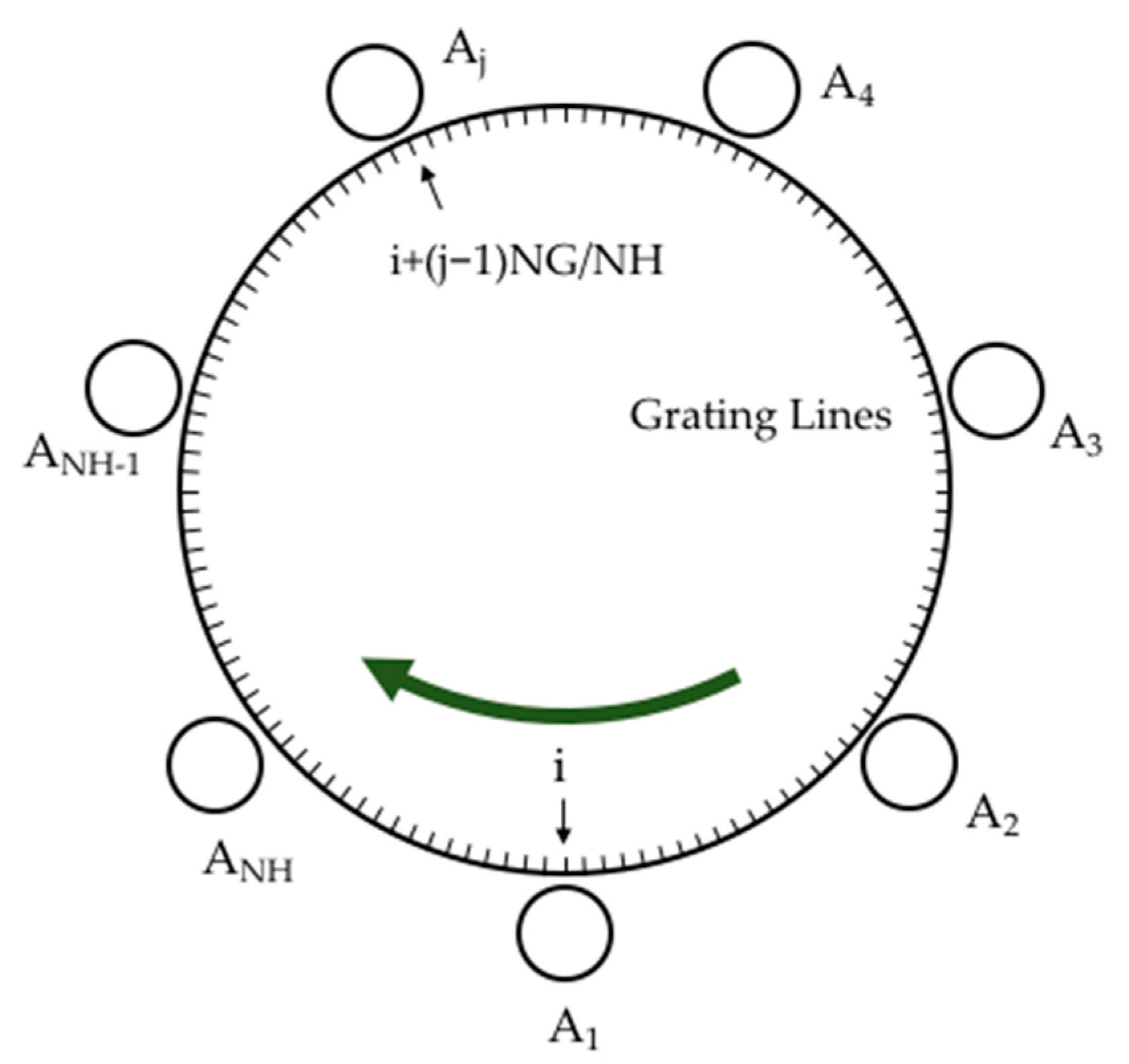
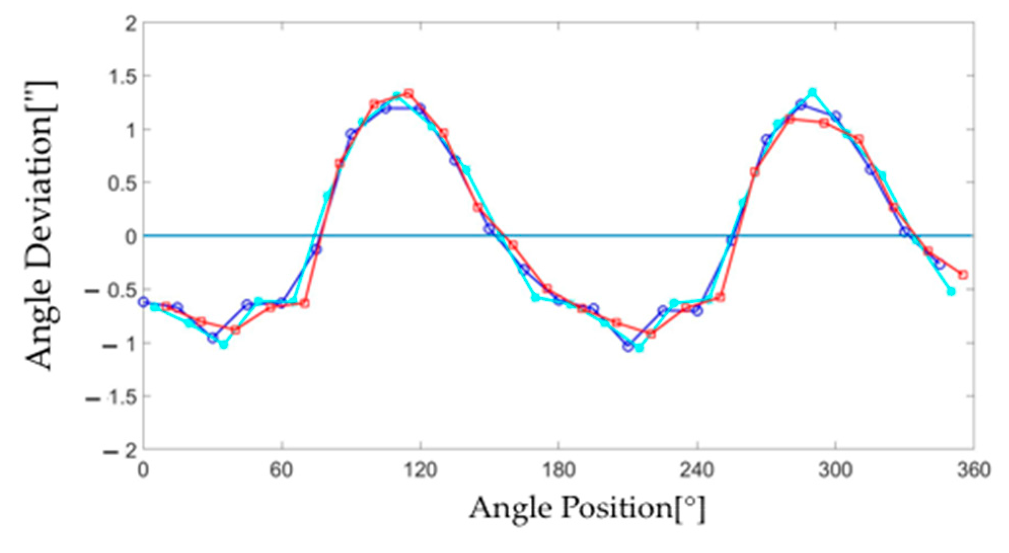
2.2. Shift-Angle Method for Rotary Encoders
Using Table 2, all of the pitch angle deviations of the 24-faced polygon can be calculated. In the second row of Table 1, the summation of all the measured values is expressed as follows:
The first term on the left-hand side of the equation denotes the measured values. According to Equation (2), the first term on the right-hand side of this equation must be zero. The second term on the right-hand side can be determined from Table 2. Consequently, setup error U1 is calculated. Therefore, using Equation (3), the angle errors, from α (0° + S), α (15° + S), …, α (345° + S) in steps of 15°, can be calculated.
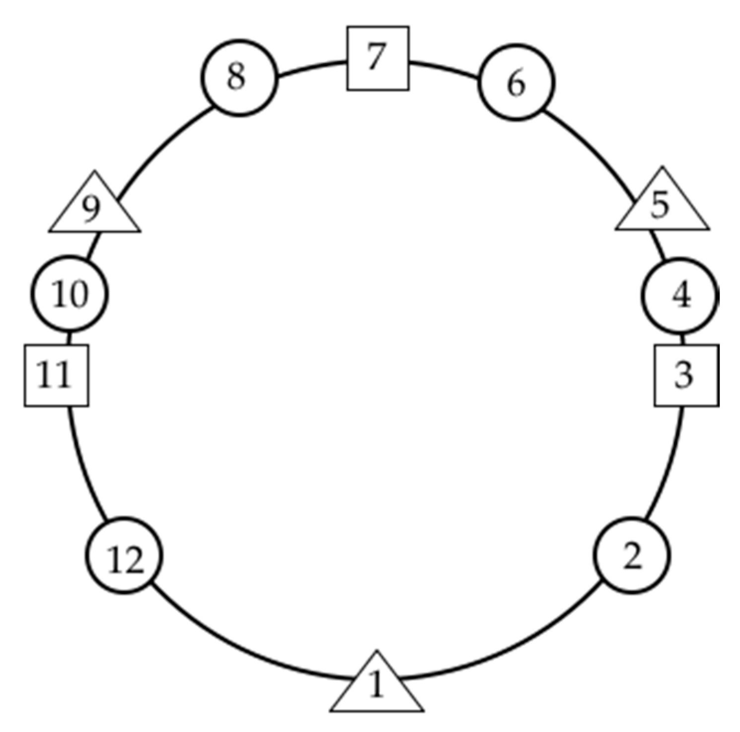
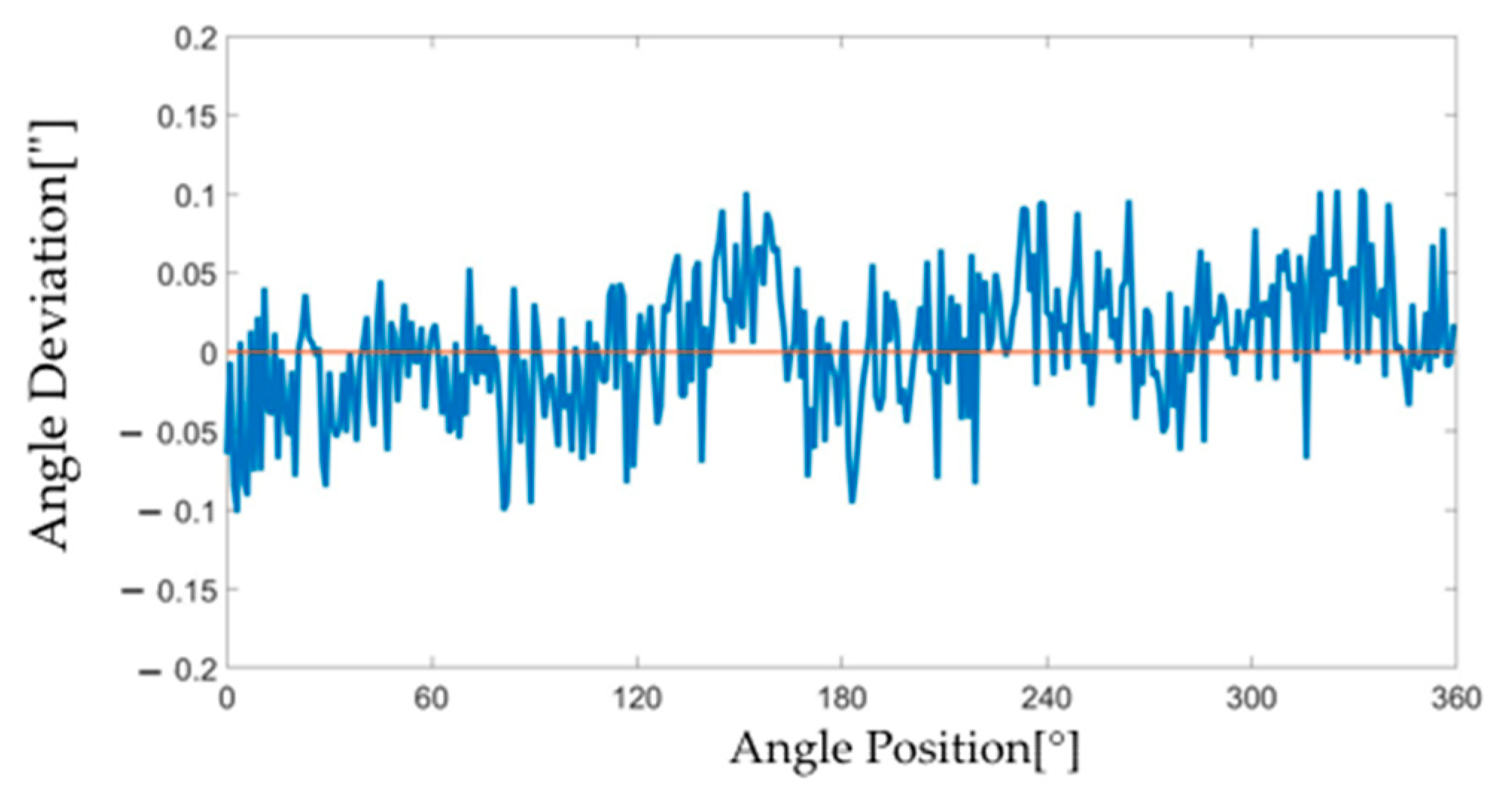
2.3. Self-Calibration
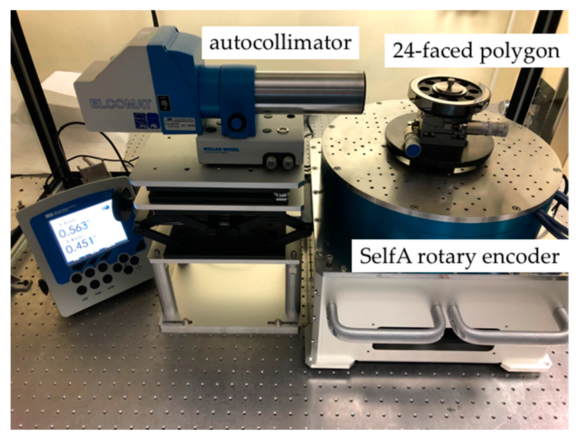
Self-calibration for calibrating the rotary encoder is used to verify the utility of the shift-angle method. The theory behind self-calibration of the SelfA rotary encoder was described in the literature [8,9,10,11]; here, we present only a brief review. Self-calibration is used to analyze the angular deviation from the angle values of multiple sensors located at equal angular intervals around the same rotary encoder. Figure 3 shows a schematic of the NH units of the sensor heads. Aj is the sensor head label, and j is the number of each sensor head. NG is the number of grating lines in the rotary encoder. All the sensor heads receive the angle value simultaneously during rotation. The received angle represents the angular deviation, which represents the difference from the ideal angle value at a specific grating line. ai denotes the angular deviation at the grating number i. During rotation, the first sensor head A1 receives the grating number i, and the jth sensor head Aj receives the grating number i + (j − 1)NG/NH. However, the angular deviation ai cannot be measured directly. The measured angular value between sensor head A1 and sensor head Aj can be expressed as follows:
Figure 3.
Relationship between the sensor heads and the grating lines of the rotary encoder [10].
The average value at the angular position from 0° to 360° is represented as follows:
where denotes the results of rotary encoder self-calibration.
3. Experiments
3.1. Shift-Angle Method
Figure 4 shows a photograph of the experimental setup. The working environment is stabilized in which the temperature is 20 ± 1 °C and relative humidity is 45 ± 10%. The 24-faced polygon is mounted at the center of the SelfA rotary encoder (e-motionsystem, Inc., Shinagawa City, Japan, SCMS-127). The SelfA rotary encoder is equipped with 12 head sensors and a rotary encoder, which has 36,000 graduation lines at intervals of 36°. The SelfA rotary encoder is controlled by a servo motor with an air bearing. The autocollimator (MOLLER-WEDEL OPTICAL GmbH, ELCOMAT 3000) is fixed outside the SelfA rotary encoder and aligned to the polygon.
Figure 4.
Photograph of the experimental setup.
The shift-angle S is 0°. The first face of the 24-faced polygon is the starting face located at 0° of the SelfA rotary encoder, as illustrated in Figure 5a. The collimated beam of the autocollimator is aligned to the first face. The angle of the autocollimator is adjusted to approximately 0. Then, as the SelfA rotary encoder is rotated by 15° in one step, the autocollimator collimates the second face of the polygon. The autocollimator collimates successive faces of the polygon. The autocollimator measures 24 values corresponding to 0°, 15°, …, 345° in steps of 15°. The measured values are listed in the second row of Table 1. Then, as illustrated in Figure 5b, the second face is aligned with the 0° of the SelfA rotary encoder, and the autocollimator should not be moved. The SelfA rotary encoder and the autocollimator repeat the previously described procedure. The autocollimator measures 24 values corresponding to 0°, 15°, …, 345° in steps of 15°, which are listed in the third row of Table 1. Each face of the polygon is set as the starting face. The measured values (576 total) are listed in Table 1. These 576 measured values are used to calculate the different measured values listed in Table 2. All the pitch-angle deviations of the polygon can be calculated, as illustrated in Figure 6. The measured values are listed in the second row of Table 1. All the pitch angle deviations calculated using Equation (3) are listed in Table 2. The setup error, U1, is calculated. The angle errors, from α (0°), α (15°), …, α (345°) in steps of 15°, are calculated, as illustrated in Figure 7.
Figure 5.
Shift-angle method for the polygon. (a) S = 0° for the first face as the starting face. (b) S = 0° for the second face as the starting face.
Figure 6.
Calibration results for pitch angle deviations of the 24-faced polygon.
Figure 7.
Calibration results at three shift-angles. S = 0°, blue solid line and circle label; S = 5°, light blue solid line and star label; and S = 10°, red solid line and rectangular label.
As depicted in Figure 8a, the shift-angle is 5°. As the starting face, the first face is located at 5° of the SelfA rotary encoder. The SelfA rotary encoder is rotated in 23 steps. The angle positions are 5°, 20°, …, 350° in steps of 15°. The second row of Table 1 lists the measured values containing the angle errors, the pitch angle deviations, and the setup error. The pitch angle deviations are calculated in the previous measurement, where S is 0°. The setup error U can be calculated using Equation (7). Therefore, the angle errors, corresponding to 5°, 20°, …, 350° in steps of 15°, can be calculated, as illustrated in Figure 7. According to Figure 8b, the shift-angle S is 10°. As the starting face, the first face is located at 10° of the SelfA rotary encoder. The SelfA rotary encoder rotates in 23 steps. The angle positions are 10°, 35°, …, 355° in steps of 15°. SelfA angle errors, from 10°, 35°, …, 355° in steps of 15°, are calculated by following the same calculation procedure, as illustrated in Figure 7.
Figure 8.
Shift-angle method for SelfA rotary encoder at different shift-angles. (a) S = 5°. (b) S = 10°.
To check the setup error U, another method uses the curve fitting least square method. The angle error can be expressed as a Fourier series because the angle error is a periodic function in one rotation. The first term on the right-hand side of Equation (9) averages the measured angular value by the two heads. The curve fitting function can be expressed as the second periodic function as α(θ) = A*sin(2*θ + B) + U(fitting), as illustrated in Figure 9. For a shift-angle S of 0°, the measured values are fitted as A = 1.0314″, B = −2.4233, and U0(fitting) is 0.9596″. For a shift-angle S of 5°, the A and B values are fixed to check the setup error U5(fitting). The U5(fitting) value is −1.5927″. For the shift-angle S 10°, the U10 (fitting) value is 1.1545″ using the same procedure. As shown in Equation (7), the setup error U0 is 0.9596″, U5 is −1.5927″, and U10 is 0.1545″. The difference in the setup error is less 10−4″using two different methods, Equation (7) and curve fitting.
Figure 9.
Calibration results for curve fitting at three shift-angles. S = 0°, blue solid line for curve fitting and circle label for the measured values; S = 5°, light blue solid line for curve fitting and star label for the measured values; and S = 10°, red solid line for curve fitting and rectangular label for the measured values.
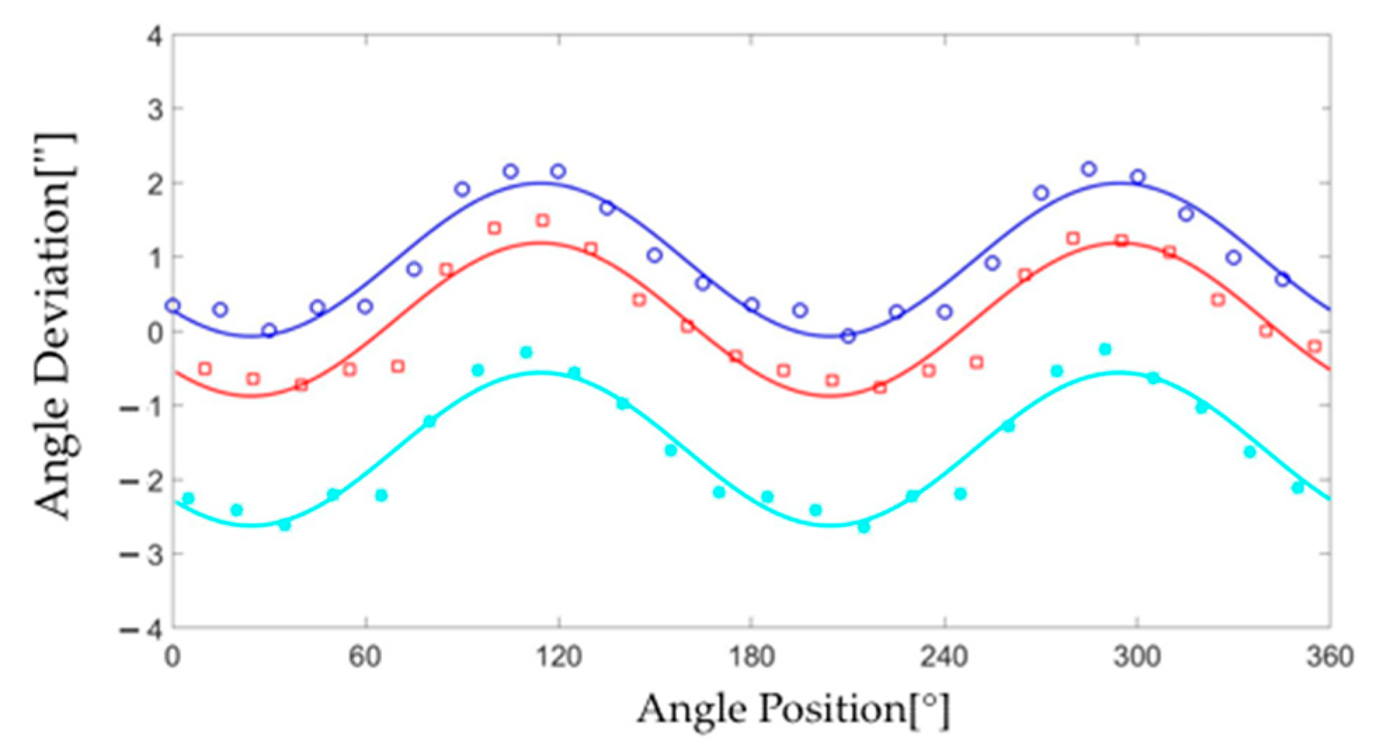
3.2. Comparison of Calibration Results Obtained Using the Shift-Angle Method and Self-Calibration
The SelfA rotary encoder is equipped with 12 head sensors and a rotary encoder. The 12 head sensors are divided into three sets and arranged as depicted in Figure 10. The first set consists of three head sensors numbered 1, 5, and 9, which are located at an interval of 120°. The second set consists of four head sensors numbered 1, 3, 7, and 11 and is located at an interval of 90°. The third set consists of seven head sensors numbered 1, 2, 4, 6, 8, 10, and 12, which are located at an interval of approximately 51.42°. The measured angles using sensors 1 and 7 are averaged and denoted by in Equation (9). ai+(j−1)NG/NH denotes the measured angles using the other sensor heads. According to Equation (9), the angles measured using the 12 head sensors can be used to calibrate the angle errors of the rotary encoder.
Figure 10.
Schematic SelfA rotary encoder of sensor heads setup. The first set is the triangle NH of 3, the second set is the square NH of 4, and the third set is the circle NH of 7 [10].
The experiment is performed on the SelfA rotary encoder using self-calibration and the shift-angle method. Figure 11 shows a comparison of the experimental results obtained using the two methods. In the experiment, the shift-angles are set from 0° to 14°. The angle errors range from 0° to 359° in steps of 1°. The self-calibration method is used to calibrate the SelfA rotary encoder at the same angle. Figure 12 depicts the difference in results using the shift-angle method and self-calibration. The difference in results is less than ±0.1″.
Figure 11.
Calibration results for the rotary encoder obtained using self-calibration and shift-angle method. Self-calibration, red dash line; and shift-angle method, blue solid line.
Figure 12.
Difference in calibration results between self-calibration and shift-angle method.
3.3. Uncertainty Evaluation
According to the ISO Guide to the Expression of Uncertainty in Measurement (GUM) [21], measurement uncertainties originate from several sources. The first step is to build a function that relates the angle error α, the measured value ε, and the pitch angle deviation β, as expressed in Equation (3). The combined standard uncertainty is expressed as follows.
The measured value uncertainty is evaluated using the repeatability of angle error measurement, resolution of the autocollimator, traceability of the autocollimator, angle error of the autocollimator, resolution of the SelfA rotary encoder, and residual setup error calculation.
- (1)
- Repeatability of angle error measurement.
Repeatability is determined using multiple measurements. The measured results of the shift-angle method, ranging from 1° to 360°, are computed as the average of six measurement results. The maximum standard deviation of all angle errors is 0.13.
The degree of freedom is 5.
- (2)
- Resolution of the autocollimator.
The resolution of the autocollimator is 0.001″. The distribution assumes a rectangular probability.
The relative uncertainty is estimated as 10% with 50 degrees of freedom.
- (3)
- Traceability of the autocollimator.
The calibration certificate declares that the uncertainty is 0.01″ with a coverage factor k of 2 (95% confidence level).
The relative uncertainty is estimated as 0% with degrees of freedom.
- (4)
- Angle error of the autocollimator.
In the calibration certificate, the maximum error is 0.05″ in the measurement range of ±1000″. The distribution assumes a rectangular probability.
The relative uncertainty is estimated as 10% with 50 degrees of freedom.
- (5)
- Resolution of SelfA rotary encoder.
The resolution of the SelfA rotary encoder is 0.04″. The distribution assumes a rectangular probability.
The relative uncertainty is estimated as 10% with 50 degrees of freedom.
- (6)
- Residual setup error calculation.
The difference between the setup error calculation, in Equation (7), and curve fitting is less 10−4″. The distribution assumes a rectangular probability.
The relative uncertainty is estimated as 10% with 50 degrees of freedom.
The measured value uncertainty , which is the root sum square of all uncertainty contributions, is 0.0676″. According to the Welch–Satterthwaite equation [21], the effective degree of freedom νeff of the measured value uncertainty is 12.
The measured value of uncertainty is evaluated based on the repeatability of the pitch angle deviation measurement.
- (7)
- Repeatability of the pitch angle deviation measurement, β.
Repeatability is determined using multiple measurements. The pitch angle deviations, from the first to the 24th face, are the average of the six measurement results. The maximum standard deviation for all pitch angle deviations is 0.12″.
The degree of freedom is 5.
The setup error uncertainty is caused by the noncentrality of the autocollimator beam on the polygon face and the eccentricity of the polygon setup.
- (8)
- Setup error of the polygon, U.
The misalignment error of the polygon is 0.05″. The distribution assumes a rectangular probability.
The relative uncertainty is estimated as 10% with 50 degrees of freedom.
The values of the two sensitivity coefficients / and are 1. As shown in Table 2, the pitch angle deviations are calculated using n∗n measured values. According to the reference paper [22], the sensitivity coefficient can be expressed as follows:
where n is the number of faces of the polygon. In this case, n is 24 and / is 0.0401.
In Table 3, the combined standard uncertainty of the shift-angle method, the root sum square of all uncertainty contributions, is 0.07″. The effective degree of freedom νeff of the combined standard uncertainty is 13. Thus, the appropriate coverage factor can be set to k = 2.31 from the t-distribution of the aforementioned effective degree-of-freedom value. The expanded uncertainty for a confidence level of 95% in Ushift is given as follows:
Usfhift = 0.15″ (k = 2.16)
Table 3.
Combined uncertainty for shift-angle method.
For self-calibration, two uncertainty sources should be considered: the resolution of the SelfA rotary encoder and repeatability of self-calibration. The first is described above. The self-calibration results, ranging from 1° to 360°, are computed as the average of the six measurement results. The maximum standard deviation of all angle errors is 0.01″. The standard uncertainty is 0.01″/ = 0.0041″. The combined standard uncertainty, the root sum square of the two uncertainty contributions, is 0.01″. The effective degree of freedom νeff of the combined standard uncertainty is 53. Thus, the appropriate coverage factor can be set to k = 2.01 from the t-distribution of the aforementioned effective degree-of-freedom value. The expanded uncertainty for a confidence level of 95% is 0.02.
The reliability of measurements by the shift-angle method is calculated as the En number, given as follows:
where α (θ) is the measured results of the shift-angle method with uncertainty Ushift, and μ is the self-calibration results with uncertainty Uself. Figure 12 shows the difference in calibration results between self-calibration and the shift-angle method. The maximum En number is 0.69, which is less than 1. The En number means that the shift-angle method is considered reliable.
4. Discussion and Conclusions
In this study, we propose a shift-angle method for calibrating rotary encoders. With this method, we use the autocollimator and the 24-faced polygon as an example. In practice, the polygon with any number of faces can be used. The traditional method uses an autocollimator and a 24-faced polygon, and the angles at which it can be calibrated are limited by the pitch angle of the polygon. However, by using the shift-angle method, the angles smaller than the pitch angle of the polygon can be calibrated.
We set-up the autocollimator and the 24-faced polygon on the SelfA rotary encoder to verify the proposed shift-angle method. Twelve sensor heads and one rotary encoder are installed in the SelfA rotary encoder. The SelfA rotary encoder can also be calibrated using a self-calibration. Therefore, the SelfA rotary encoder is calibrated using the proposed shift-angle method and self-calibration. The difference in calibration results obtained using the two methods is less than ±0.1″. According to the ISO GUM, the expanded uncertainty of the proposed shift-angle method is 0.15″. According to the En number evaluation, the proposed shift-angle method is feasible for practical use.
Author Contributions
Conceptualization, T.-H.H. and T.W.; methodology, T.-H.H. and T.W.; validation, T.-H.H. and T.W.; data curation, T.-H.H., T.W. and P.-E.H.; writing—original draft preparation, T.-H.H.; writing—review and editing, T.-H.H. and T.W. All authors have read and agreed to the published version of the manuscript.
Funding
This work was supported by Industrial Technology Research Institute and National Institute of Advanced Industrial Science and Technology.
Institutional Review Board Statement
Not applicable.
Informed Consent Statement
Not applicable.
Conflicts of Interest
The authors declare no conflict of interest.
References
- Lu, X.D.; Trumper, D.L. Self-calibration of on-axis rotary encoders. CIRP Ann. 2007, 56, 499–504. [Google Scholar] [CrossRef]
- Masuda, T.; Kajitani, M. An Automatic Calibration System for Angular Encoders. Precis. Eng. 1989, 11, 95–100. [Google Scholar] [CrossRef]
- Probst, R.; Wittekopf, R.; Krause, M.; Dangschat, H.; Ernst, A. The new PTB angle comparator. Meas. Sci. Technol. 1998, 9, 1059–1066. [Google Scholar] [CrossRef]
- Probst, R. Self-calibration of divided circles on the basis of a prime factor algorithm. Meas. Sci. Technol. 2008, 19, 015101. [Google Scholar] [CrossRef]
- Geckeler, R.D.; Link, A.; Krause, M.; Elster, C. Capabilities and limitations of the self-calibration of angle encoders. Meas. Sci. Technol. 2014, 25, 055003. [Google Scholar] [CrossRef] [Green Version]
- Jiao, Y.; Dong, Z.G.; Ding, Y.; Liu, P.K. Optimal arrangements of scanning heads for self-calibration of angle encoders. Meas. Sci. Technol. 2017, 28, 105013. [Google Scholar] [CrossRef] [Green Version]
- Jiao, Y.; Ding, Y.; Dong, Z.G.; Huang, M.; Liu, P.K. Optimal-arrangement-based four-scanning-heads error separation technique for self-calibration of angle encoders. Meas. Sci. Technol. 2018, 29, 085005. [Google Scholar] [CrossRef]
- Watanabe, T.; Fujimoto, H.; Masuda, T. Self-calibratable rotary encoder. J. Phys. Conf. Ser. 2005, 13, 240. [Google Scholar] [CrossRef]
- Watanabe, T.; Hiroyuki, F. Application of a self-calibratable rotary encoder. Proc. ISMTII 2009, 3, 54–58. [Google Scholar]
- Watanabe, T.; Kon, M.; Nebeshima, N.; Taniguchi, K. An angle encoder for super-high resolution and super-high accuracy using SelfA. Meas. Sci. Technol. 2014, 25, 065002. [Google Scholar] [CrossRef]
- Ueyama, Y.; Furutani, R.; Watanabe, T. A super-high-accuracy angular index table. Meas. Sci. Technol. 2020, 31, 094006. [Google Scholar] [CrossRef]
- Pavlov, P.A. Aspects of the Cross-Calibration Method in Laser Gonimetry. Meas. Tech. 2015, 58, 970–974. [Google Scholar] [CrossRef]
- Pavlov, P.A. A Method for investigating the error of a laser dynamic goniometry. Meas. Tech. 2020, 63, 106–110. [Google Scholar] [CrossRef]
- Akgoz, S.-A.; Yangdayan, T. High precision calibration of polygons for emerging demands. IOP Conf. Ser. J. Phys. Conf. Ser. 2018, 1065, 142005. [Google Scholar] [CrossRef]
- Jia, H.K.; Yu, L.D.; Zhao, H.N.; Jiang, Y.-Z. A new method of angle measurement error analysis of rotary encoders. Appl. Sci. 2019, 9, 3415. [Google Scholar] [CrossRef] [Green Version]
- Reeve, P.C. The calibration of indexing tables by subdivision. NBS Int. Rep. 1975, 1–37, 75–750. [Google Scholar]
- Estler, W.T.; Queen, Y.H.; Bryan, J. An advanced angle metrology system. CIRP Ann. 1993, 42, 573–576. [Google Scholar] [CrossRef]
- Kim, J.A.; Kim, J.W.; Kang, C.S.; Jin, J.H.; Eom, T.-B. Calibration of angle artifacts and instruments using a high precision angle generator. Int. J. Precis. Eng. Manuf. 2012, 14, 367–371. [Google Scholar] [CrossRef]
- Huang, Y.; Xue, Z.; Huang, M.; Qiao, D. The NIM continuous full circle angel standard. Meas. Sci. Technol. 2018, 29, 074013. [Google Scholar] [CrossRef]
- Pisani, M.; Astrua, M. The new INRIM rotating encoder angle comparator (REAC). Meas. Sci. Technol. 2017, 28, 045008. [Google Scholar] [CrossRef]
- ISO/IEC Guide 98-3:2008. Uncertainty of Measurement—Part 3: Guide to the Expression of Uncertainty in Measurement; ISO: Geneva, Switzerland, 2008. [Google Scholar]
- Estler, W.T. Uncertainty analysis for angle calibrations using circle closure. J. Res. NIST 1998, 103, 141–151. [Google Scholar] [CrossRef] [PubMed]
Publisher’s Note: MDPI stays neutral with regard to jurisdictional claims in published maps and institutional affiliations. |
© 2022 by the authors. Licensee MDPI, Basel, Switzerland. This article is an open access article distributed under the terms and conditions of the Creative Commons Attribution (CC BY) license (https://creativecommons.org/licenses/by/4.0/).