2. Factors Impacting the Intensity of Hydroabrasive Wear of the Pumping Stages of the ESP
Mechanical impurities contained in the pumped fluid can be divided into one-component and multi-component fluids according to their composition [
18]. The classification of abrasive particles by their origin is as follows:
rock particles carried into the well during development and operation of the well;
corrosion products from borehole equipment;
particles contained in well-killing fluid;
unsecured propping agent after hydraulic fracturing;
particles of solid sludge formed by interaction of chemically incompatible fluids [
10,
19].
The concentration of mechanical impurities in the well fluid is generally not a constant value. A one-time increase in the concentration of abrasive particles (up to two orders of magnitude) is observed when the ESPs are started and wells are operated at stable production after workover or current repairs, short-term shutdowns of ESPs, and changes in operation parameters of the reservoir pressure maintenance systems.
The intensity of abrasive wear in the pumping stages of an ESP depends on the number of influencing factors and can generally be described by Equation (1):
where
Ki—relative mass change of the wearing part of the pumping stage of ESP;
t—time of the exposure of the abrasive particles to the wearing part;
dKi/dt—hydroabrasive wear rate;
R,
F,
ρ,
Hc,
C—size, shape, density, hardness, and concentration of abrasive particles of mechanical impurities, respectively;
K—corrosiveness of the medium;
Hd—hardness of the surface of the wearing part;
Fd—shape of the surface of the wearing part; ω—rotational velocity of driving shaft of the pump [
20,
21].
The intensity of the wear of parts of the pumping stages is not uniform along the length of the pump section [
22].
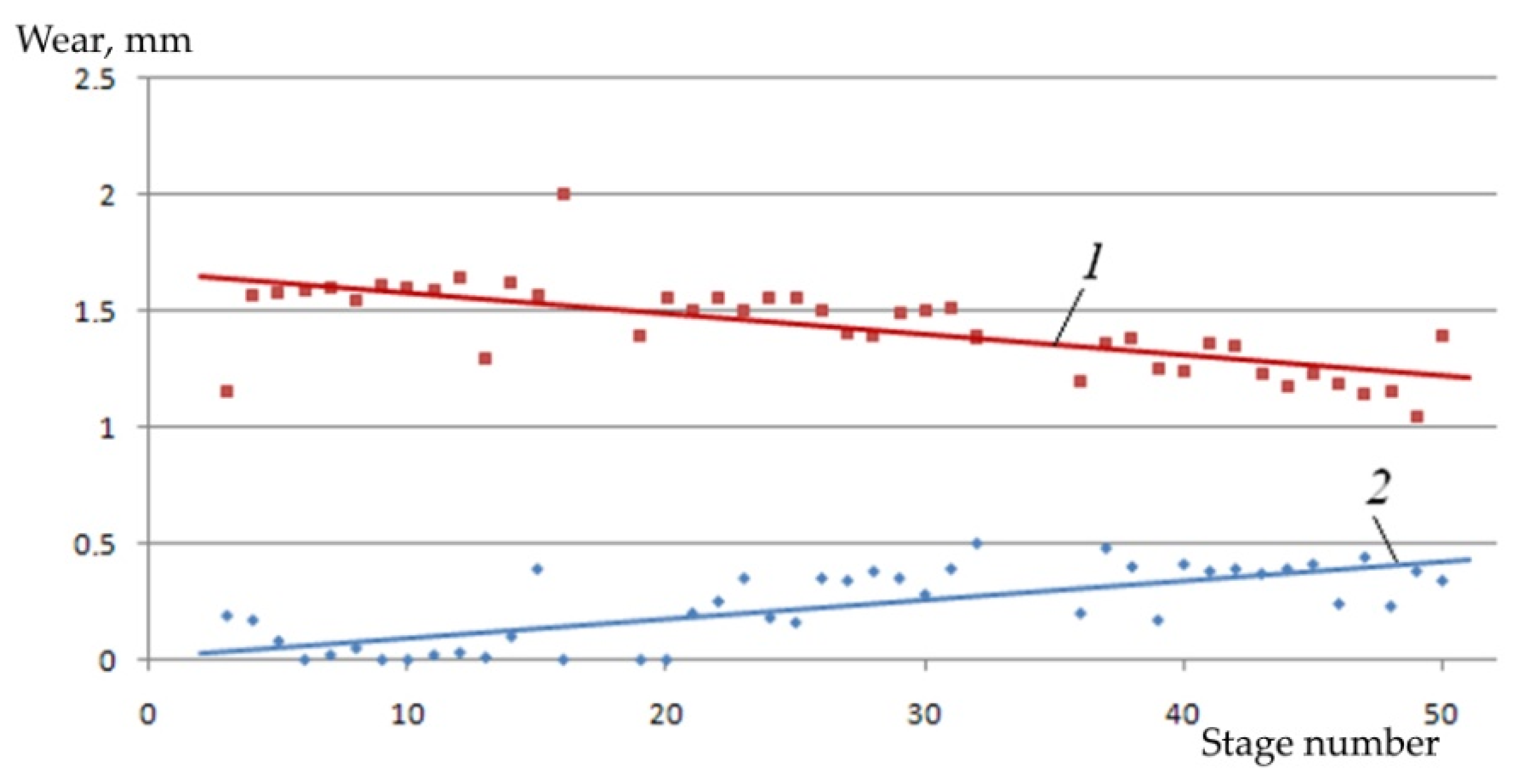
Figure 1 shows the results of the accelerated bench tests, published in [
9], from an evaluation of the wear of thrust washers of the pump section assembled from 50 stages of VNN5A-100.
The tests were carried out on a bench with a closed circulation of fluid through the test pumping section for 6 h. The pumped fluid was water with silica sand having a concentration C = 10 g/L. Coarse silica sand having a grain size R = 800…1000 μm was used in the first stage of the testing, and fine sand having a grain size R = 10…20 μm was used in the second stage.
The analysis of the obtained results showed that coarse particles of silica sand are more abrasive to the thrust washers of the first stages of the pumping section. Subsequently the abrasion ability of coarse particles of mechanical impurities decreases. Fine silica sand particles accumulate and settle in cavities of the pumping stages. The concentration of such particles in cavities of local accumulation increases in the direction of the flow from the inlet to the outlet of the pump section. Therefore, the thrust washers of the successive pumping stages (in the direction of the flow) are worn by the fine sand more intensively than the thrust washers of the stages closest to the flow inlet of the pump section (
Figure 1, position 2).
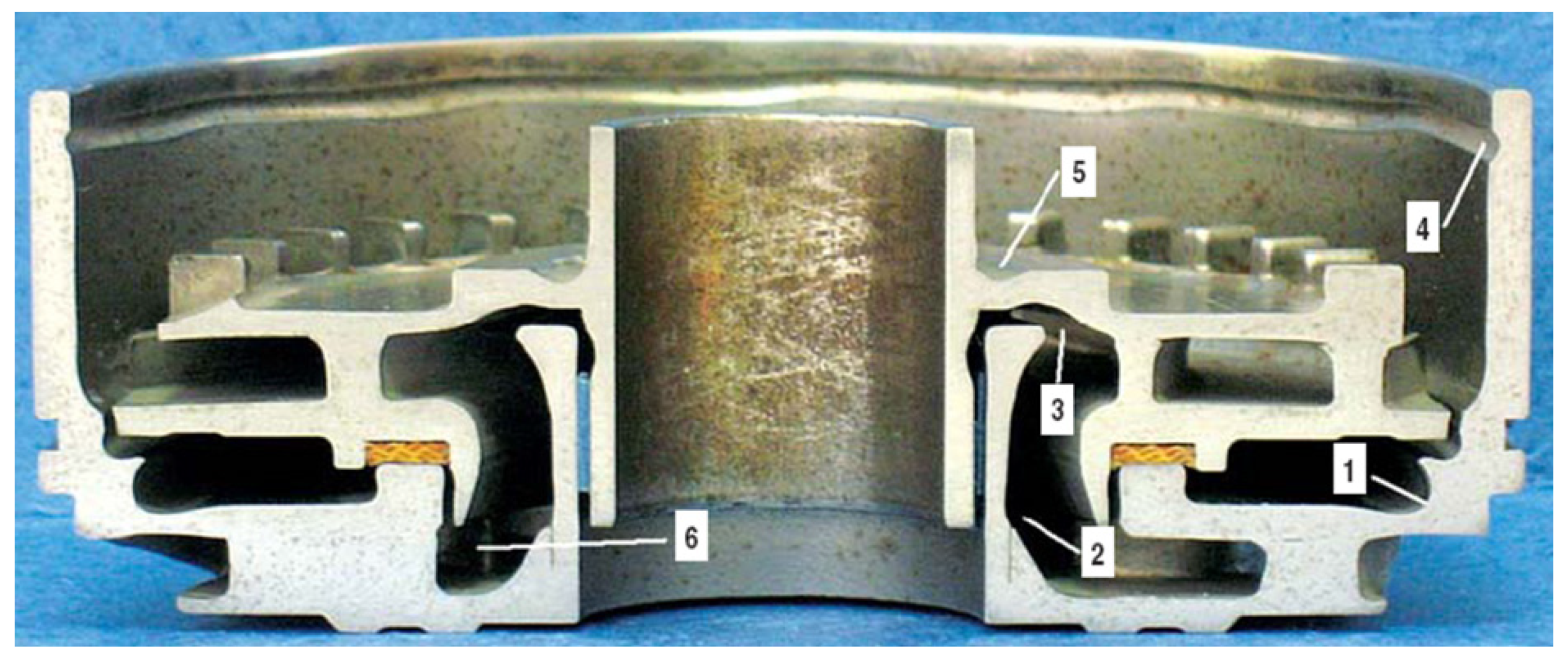
Six basic zones of intensive development of hydroabrasive wear of pumping stages of an ESP were determined in previous papers [
11,
23] (
Figure 2). These are: the practically closed cavity
1 between the lower impeller disk and the upper disk of the guide apparatus; area
2 of fluid flow rotation in the guide apparatus; area
3 of fluid flow rotation in the stage impeller; area
4 of fluid flow rotation at the fluid inlet to the channels of the guide apparatus of the next stage; area
5 of the upper impeller disk; and area
6 of the concave side of the guide apparatus vane.
Intensive development of abrasive wear of the guide apparatus of the VNN5A-100 pumping stage in area 1 is determined by the impact of particles of mechanical impurities separated from the main flow and accumulated under the lower impeller disk. At the same time, a complex of forces acts on abrasive particles moving in the liquid:
forces co-directional to the rotation of the impeller and caused by the friction of the liquid against the bottom disk of the impeller;
centrifugal forces, which press the particles of the mechanical impurities against the walls of the guide apparatus;
forces directed towards the center of the stage and arising from fluid overflow through the seals.
The aforementioned factors determine the formation of vortices in the cavity 1. Their presence causes the intensive movement of particles of mechanical impurities along the walls of the guide apparatus and, as a consequence, abrasive wear of the metal. The intensity of the wear increases with the size of the vortices.
Hydroabrasive wear in the areas 2–4 and 6 is slower than that in area 1. The accumulation of the particles of mechanical impurities and the formation of vortices is caused by the change in the direction (rotation) of the pumped fluid flow.
The presence of fluid overflow in the pumping stage between the bush of the guide apparatus and the middle thrust washer of the impeller is the reason for the development of the wear in the area 5. The fluid containing the particles of mechanical impurities flows from the pumping stage into the previous stage along the direction of the flow and destroys the impeller thrust washers. This process develops most intensively at higher rotation velocities of the drive shaft of the ESP (≈6 thousand rpm), which causes the destruction of impellers, i.e., the cutting of disks and their separation from the hub sleeve.
The American Petroleum Institute (API) methodology considers the influence of geometric parameters and physical–mechanical properties of particulate mechanical impurities on their wearing capacity. This is evaluated by the value of the complex abrasiveness index of mechanical impurities, which is generally described by Equation (2):
where
AI—abrasiveness index of mechanical impurities.
The quantitative value of the abrasiveness index is determined empirically by Equation (3):
where
Kr—roundness coefficient of the particles of mechanical impurities, defined according to the
API methodology;
Ks—the spherical shape factor of the particles of mechanical impurities, defined according to the
API methodology;
M−0.25%—mass fraction of abrasive particles of mechanical impurities with the grain size less than 0.25 mm, %;
Mir%—mass fraction of the particles of mechanical impurities insoluble in acid (mass fraction of insoluble residue), %;
Mq%—fraction of quartz particles in the total mass of mechanical impurities, % [
7,
24,
25].
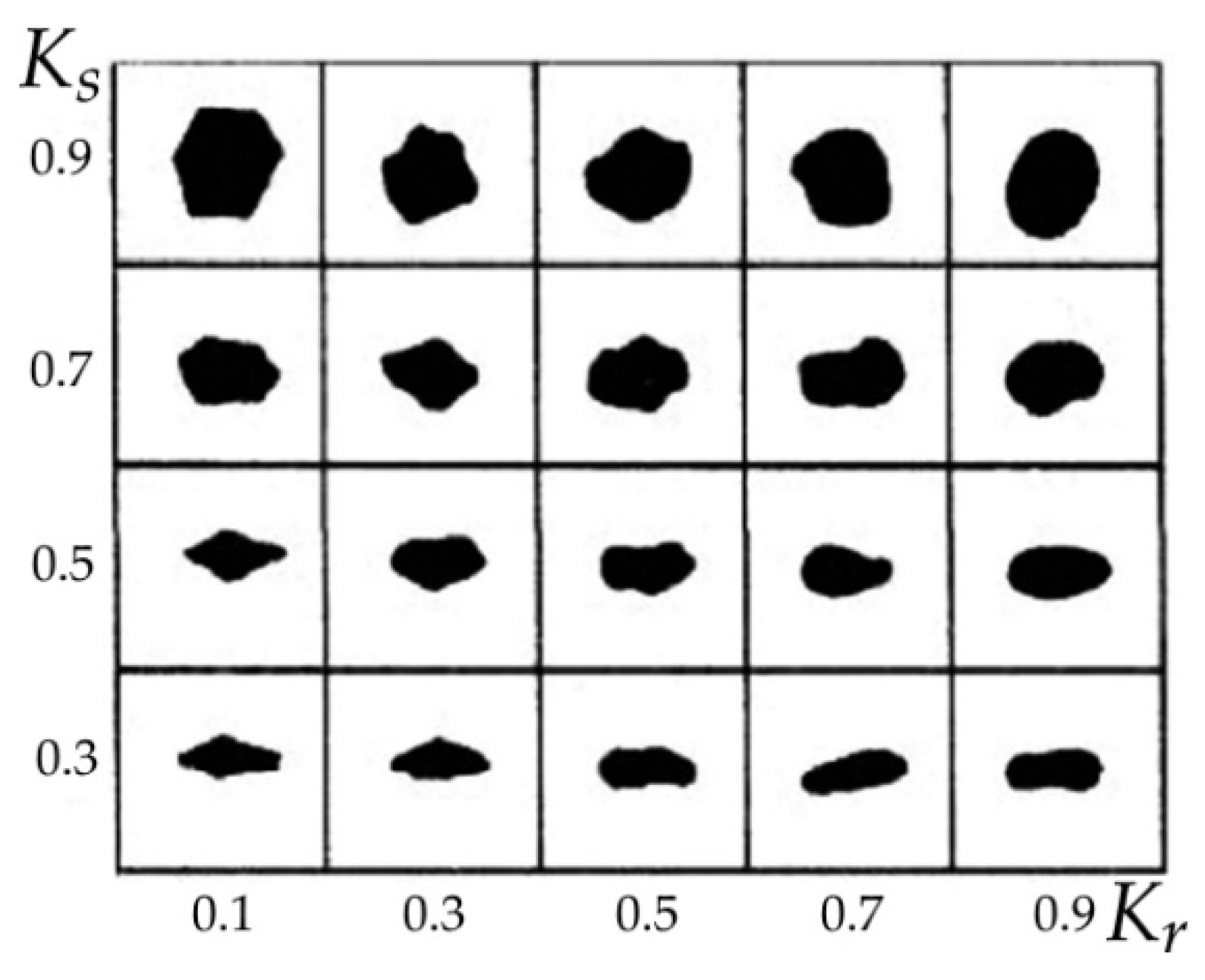
Analysis of Equation (3) shows that the greatest influence on the abrasion ability and the abrasiveness of the particles of mechanical impurities interacting with the parts of submersible pumping equipment is the shape of the solid particles, i.e., their roundness and spherical factor. The graph used for visual determination of values of roundness coefficients
Ko and spherical shape factors
Ks of solid particles of mechanical impurities is presented in
Figure 3 [
26,
27].
Most of the methods used for protection of ESPs against hydroabrasive wear are aimed at reduction in the concentration and size of particles of mechanical impurities passing through the pumping stages in the fluid flow, and increasing resistance of the pumping stage’s materials to abrasive wear. In addition, changing the shape of particles of mechanical impurities (increasing their spherical shape factor and roundness) entering an ESP, for example, by means of preliminary mechanical action, reduces their abrasiveness and wear capacity.
3. Analysis of the Protection Methods for ESPs Producing Well Fluid with High Content of Mechanical Impurities
Methods for protecting ESPs operating under conditions of high content of mechanical impurities in the well fluid are traditionally divided into technological and technical approaches [
28,
29,
30,
31].
The first group of methods includes measures associated with the limitation of formation fluid withdrawal from production wells, transition to the continuous operation mode of the ESP unit, and reduction in the rate of work of reservoir pressure maintenance systems. Thus, the probability of abrasive particles being lifted by the well fluid flow and the probability of mechanical impurities passing through the ESP is decreased. Necessary attention is paid to the selection of well-killing fluids’ compositions, corrosion control of borehole equipment, and analysis of chemical compatibility of formation products with fluids injected into the well and formation [
1].
The implementation of technological methods to protect ESPs against mechanical impurities is expensive, complicated, and generally leads to the reduction in production well productivity.
Technical methods to protect ESPs against the harmful effects of mechanical impurities include the use of submersible pumps in abrasion-resistant designs [
32] and the use of pre-wired devices.
Wear-resistant pumping stages are made from high-strength materials. The designs of guide apparatus, impellers, thrust washers, and interstage seals are adapted to abrasive particles. These designs are often based on the implicit abrasion resistance of the parts of an ESP, and have wide prospects for use and improvement. However, the cost of abrasion-resistant ESP units is 1.5–2 times higher than units of a conventional design [
15,
16].
The pre-wired devices used to protect ESPs from mechanical impurities are divided into separators and filters. These are installed in the well in order to clean the sand, propping agent, and other mechanical impurities from the reservoir and have two main functions: to protect the pump from solid particles and to create a minimum hydraulic resistance at the pump inlet.
Separators of mechanical impurities are installed in wells under ESP submersible motors and provide separation of solid particles from fluid flow by gravitational or centrifugal forces. A common disadvantage of these devices is the change in efficiency (value of mechanical impurities’ separation coefficient) depending on the well flow rate, formation fluid properties, and mechanical impurities.
ESP filters are divided according to their operating principle into surface and volumetric filters, i.e., slotted or wire-line and disk filters, respectively. The efficiency of the filters is virtually independent of changes in borehole conditions. Currently, the slotted filters are the most widely used, and are characterized by a simple design, high maintainability, and low cost [
4,
25,
27].
The disadvantage of filters is their low dirt capacity, which causes ESP failures due to supply failures in case of clogging of filter elements. The existing methods of filter cleaning and permeability recovery directly in well conditions are inefficient, complicated, and have significant financial expenses, thus limiting their application. Usually, filter plugging determines the necessity to lift the ESP out of the well in oil production practice [
12,
33]. Exceptions are the filters equipped with check valves, which are opened when the filter element is clogged. In this case, the fluid flow enters the ESP without purification, together with particles of mechanical impurities, thus bypassing the clogged filter element [
15,
16].
Analysis of the known methods of protection of working stages of downhole ESPs against hydroabrasion shows the search for cost-effective, efficient, and versatile technical solutions, to provide an increase in the ESP operating time in wells, is complicated by the high content of mechanical impurities in the produced oil. One of the promising directions in solving this problem is the creation of ESP inlet and downhole filters with the ability to clean and restore the permeability of clogged filter elements in the conditions of the well, without lifting the submersible pump unit to the surface.
4. Analysis of the Protection Methods for ESPs Producing Well Fluid with High Content of Mechanical Impurities
Self-cleaning slotted filters were developed and patented by the authors together with the specialists of “Novomet-Perm” JSC (Perm, Russia). These filters provide an increase in ESP operating time when producing well fluid with a high content of mechanical impurities.
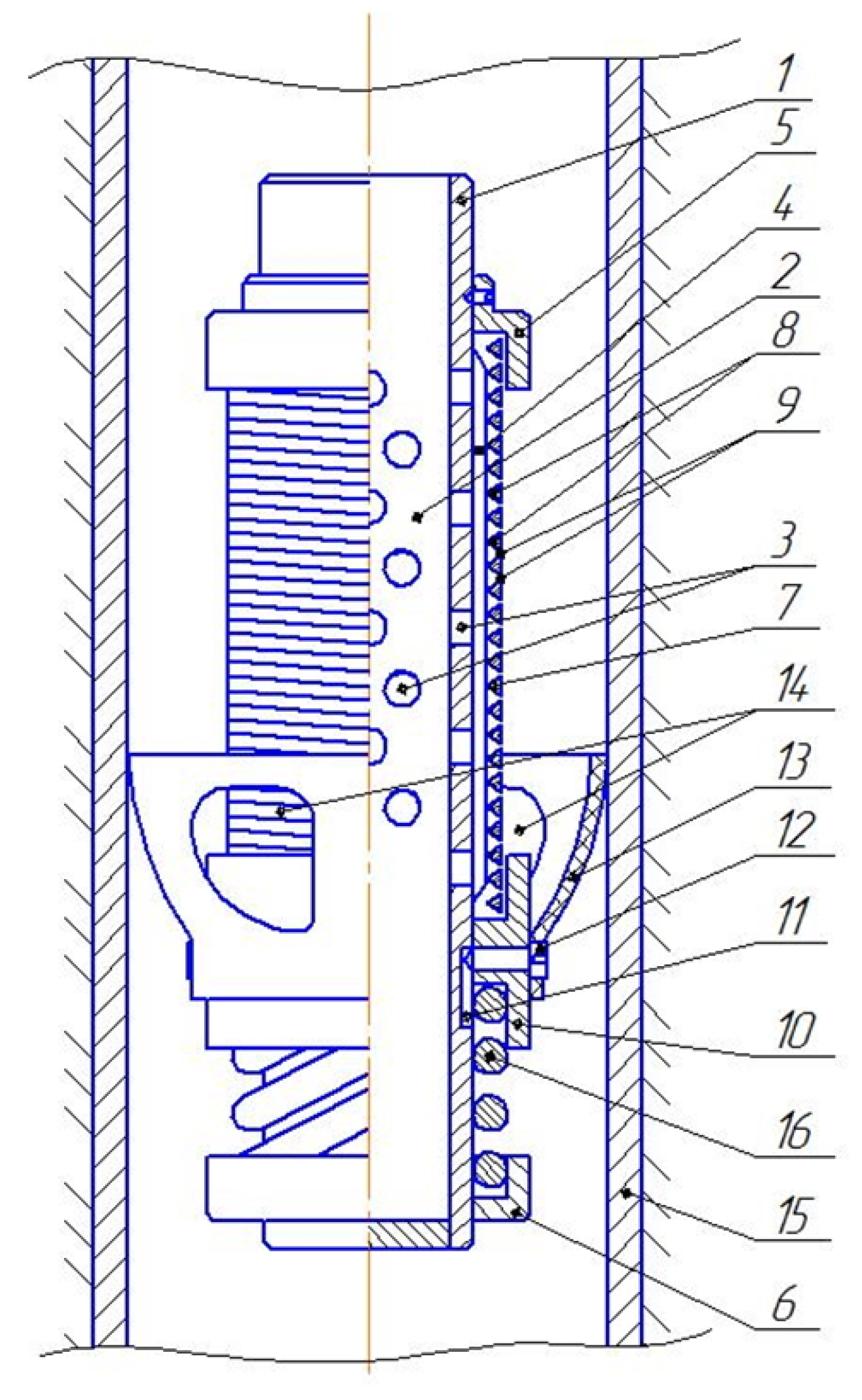
Figure 4 shows the scheme of a downhole ESP slotted filter with deformable filter element [
34]. The slotted filter contains a tube (
1) with a filtering section (
2), which is perforated with through holes (
3) and has stiffening ribs (
4) on the external surface. Upper (
5) and lower (
6) stationary stops are mounted in the form of glasses at the ends of the tube
1 with annular gaps between the inner surface of the walls and the outer surface of the tube
1. A deformable filter element (
7) is concentrically placed around the tube (
1). This filter element (
7) is made as a coiled wire (
8), with the slots (
9) formed between the coils. The filter element (
7) is placed between the upper fixed stop (
5) and movable double-sided stop (
10). The end coils of the spiral wire (
8) of the filter element (
7), placed inside the annular gaps, are rigidly connected to the stops (
5) and (
10).
The double-sided movable stop (10) moves axially along the pipe (1) via the limiting grooves (11), into which the ends of the screws (12) are sunk. A resilient element made in the form of a cuff (13) with through holes (14) is fixed on the lateral surface of the double-sided movable stop (10), with the help of screws (12).
The cuff (13) is in contact with the walls of the production tubing (15) in the borehole. There is a spring (16) between the lower stationary stop (6) and the double-sided movable stop (10) with the support on their ring pads. The force of the spring 16 exceeds the elastic deformation of the filter element wire (7).
The slotted filter together with the submersible pump unit is lowered into the borehole. The borehole fluid containing mechanical impurities flows freely to the surface of the filter element (
7) through the through holes (
14) of the cuff (
13). Passing between the slots (
9) of the coils of the coiled wire (
8) of filter element (
7), the borehole fluid is cleaned and flows inside the tube (
1) through the holes (
3) of filtering section (
2), where it further rises into the borehole pump (not shown on
Figure 4). Particles of mechanical impurities, separated from borehole fluid, are deposited on the outer surface of the filter element (
7), creating “bridges” of deposits and reducing its permeability (flow capacity) with time.
Periodic cleaning of the filter element 7 is carried out by deformation of the tubing on which the ESP is suspended in the well by changing the pressure at the wellhead.
It is known that when the oil-well tubing is filled with well fluid and excessive pressure
Pw is created at the wellhead, the oil-well tubing deforms by the value Δ. This value can be calculated using Equation (4):
where Δ—deformation value of the oil-well tubing, m;
L—the length of the oil-well tubing, m;
E—modulus of elasticity of tubing material, MPa;
μ—Poisson’s ratio of tubing material; γ—specific weight of tubing, N/m
3; γ
f—specific weight of fluid in tubing, N/m
3;
Ft—area of tubing passage, m
2;
F—area of annular cross-section of tubing, m
2;
Pw—pressure at the wellhead, atm [
35].
The left side of Equation (4) is a constant when the wellhead pressure varies with the filled oil-well tubing, i.e.,
Therefore, the deformation value Δ of the oil-well tubing when changing
Pw is determined by Equation (6):
The following conditions were considered for execution of calculations using Equation (6): the oil-well tubing consists of tubes with an outside diameter of 73 mm and wall thickness of 5.5 mm; tubing material—30CrMA steel (foreign analogues are 25CrMo4, 34CrMo4); modulus of elasticity of tubing material E = 2.12∙105 MPa; Poisson’s ratio of tubing material μ = 0.3; tubing length L = 1000 m; area of tubing passage Ft = 30.2∙10−6 m2; area of annular cross-section of tubing F = 11.7∙10−6 m2. If excess pressure Pw changes from 0 to 50 atm at the wellhead, the deformation value of the oil-well tubing is Δ = 0.024 m.
Therefore, the submersible pump unit together with slotted filter is lowered along the production well by the value Δ = 0.024 m when the wellhead pressure increases to
Pw = 50 atm and the length of the tubing is
L = 1000 m. Switching off the pump unit and releasing the pressure at the wellhead to
Pw = 0 atm lifts the pump unit along the production well by the same value Δ = 0.024 m. At the same time, the cuff
13 is in contact with the walls of the well
15 (
Figure 4). The aforementioned factors cause short-term stretching of deformable filter element
7, increasing of the size of slots
9, destruction of “bridges” of deposits of mechanical impurities, and restoration of the permeability of the filter element
7. Subsequently, the spring
16 compresses the stop
10 with the cuff
13, which leads to the restoration of the original dimensions of slots
9 and the filter element
7.
The use of slotted filters with rigid, non-deformable filter elements equipped with movable cleaning devices is possible when developing ESPs installed on a load-bearing cable when working with complex wells.
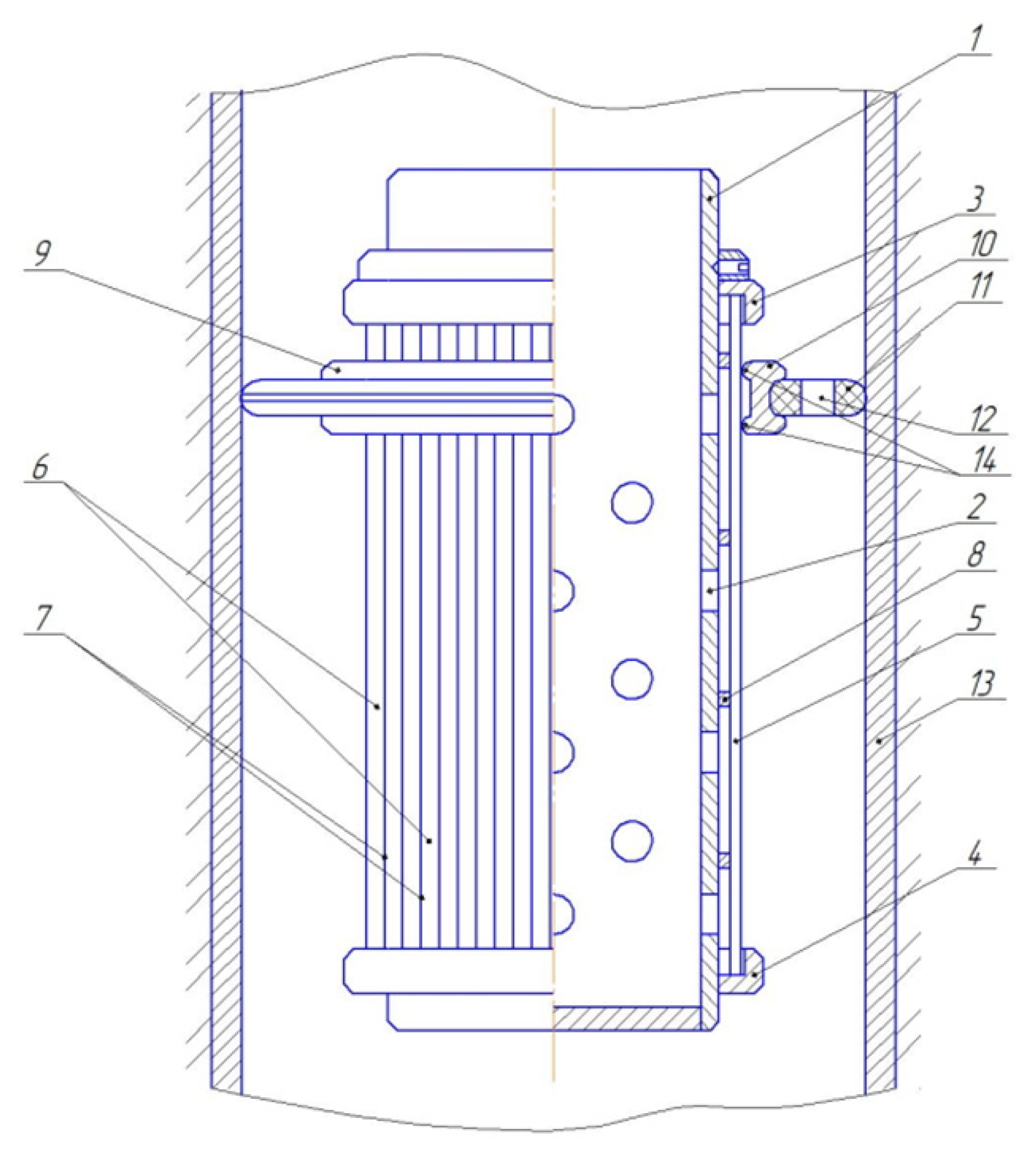
Figure 5 shows a slotted borehole self-cleaning filter lowered along the oil-well tubing as a part of an ESP unit on a load-bearing cable [
36].
The slotted filter contains a tube 1, which is perforated with through holes 2. Upper 3 and lower 4 end rings are mounted on the ends around the tube 1. Filter element 5 is concentrically placed around the tube 1. The filter element 5 is made in the form of longitudinal bars 6, between which slots 7 are formed. Transversal bars 8, connected to the longitudinal bars 6, are provided in order to make the structure of filter element 5 rigid. The ends of the filter element 5 are placed inside the annular gaps of the end rings 3 and 4.
The movable device 9 for cleaning from mechanical impurities, made in the form of a ring 10 with a fixed resilient element 11 with through holes 12, is concentrically installed on the outer surface of the filter element 5. The resilient element 11 is in contact with the inner walls of the tubing 13.
There are support-cleaning elements 14 on the inner side of the ring 10. The movable cleaning device 9 is designed to move along the longitudinal bars 6 and slots 7 of the filter element 5, whereby the support-cleaning elements 14 act on the deposits of mechanical impurities and clean the surface of the filter element 5. The support-cleaning elements 14 of the movable device 9 for cleaning the filter element 5 can be made in the form of concentric knives or brushes.
The slotted filter together with the submersible pump unit is lowered into the borehole along the oil-well tubing. The borehole fluid containing mechanical impurities flows freely to the surface of the filter element
5 through the through holes
12 of the resilient element
11. Passing between the slots
7 of the longitudinal bars
6 of the filter element
5, the borehole fluid is cleaned and flows inside the tube
1 through the holes
2, where it further rises into the borehole pump (not shown on
Figure 5). The upper
3 and lower
4 end rings fix the filter element
5 in relation to the tube
1.
Particles of mechanical impurities, separated from the borehole fluid, are deposited on the outer surface of the filter element 5, creating “bridges” of deposits and reducing its permeability (flow capacity) with time. The borehole pump motor is switched off to stop the borehole fluid withdrawal when the filter element 5 is clogged. The entire submersible pump unit is lifted on a load-bearing cable along the walls of the tubing 13 towards the wellhead at the distance of 10–15 m. The resilient element 11 is in contact with the inner surface of the walls of the tubing 13 during the lifting of the pump unit. The cleaning device 9 moves along the longitudinal slots 7 of the filter element 5 due to the friction forces resulting from the contact between the resilient element 11 and the inner surface of the tubing walls 13. At the same time the support-cleaning elements 14, made in the form of concentric knives or brushes, destroy deposits of mechanical impurities and clean the surface of the filter element 5, thereby restoring its permeability (flow capacity).
The particles of mechanical impurities separated from the surface of the filter element 5 are deposited in the dib hole of the well through the holes 12 in the resilient element 11. The submersible pump unit is lowered on the load-bearing cable in order to return the cleaning device 9 to its original position. Thus, the direction of the friction force created at the contact of the tubing walls 13 and the resilient element 11 is changed. The cleaning device 9 is moved along the surface of the filter element 5 to its original position.
Therefore, the operating time between failures of the slotted filter in the well is increased by the periodic mechanical cleaning of the filter element, which results in the increase in the ESP’s operating time.
Installation of the ESP in wear-resistant designs in the first and the last pumping stages of the section reduces the abrasion ability of fine particles having a grain size smaller than the size of the slots of the filter element. Thus, particles of mechanical impurities will become smooth when they enter the pump, and, consequently, the abrasiveness of the first stages will be reduced. The wear arising due to the concentration of particles of mechanical impurities in the pumping stages close to the flow outlet will be less intensive.


