Abstract
Purpose: In the present work, different combinations of fits and accuracies, in relation to the profiles of mating parts, have been analysed in order to assess the degree of the engagement of transmissions that contain intermediate rolling elements. The aim of this work is to determine which fits have decreased accuracy, but nevertheless provide a minimum manufacturing clearance for the transmission engagement in order to reduce the cost of parts production. Methods and materials: Considering the normal probabilistic distribution law in relation to the obtained dimensions of the manufacturing equipment, a combination of fits were selected using the incomplete interchangeability method, taking into account the peculiarities of the cycloid engagement in transmissions with intermediate rolling elements (IRE). Results: Having studied various combinations of fits of parts that are engaged in transmissions with intermediate rolling elements and a free cage (IREFC), a combination of fits for a “ring, rolling-element cam” were determined, in which a technological clearance of 3 µm is formed in the engagement. At the same time, cycloid disk profiles are manufactured according to the 9th tolerance grade, which reduces the laboriousness and cost of the production. Discussion. When reducing the manufacturing accuracy of cycloid disks, it is possible to obtain both very ample clearances and significant negative allowances. For example, having manufactured a ring with the H9 fit, rolling elements with h6 and a cam with js9, the maximum manufacturing clearance can reach 0.086 mm, while the clearance limits vary from 0.025 mm to 0.061 mm. Additionally, if mating parts are manufactured using a combination of K9-h6-js9 fits, a negative allowance varying from 0.014 mm to 0.026 mm will emerge in the engagement. Both described cases are unacceptable because both ample clearances and large negative allowances will negatively influence the working capacity of the mechanism. However, it is possible to select a combination of fits using the 9th tolerance grade of the basic parts, by which the parts will contact in the range from a small negative allowance of 1 µm to a clearance of 3–4 µm. Furthermore, if this is considered, taking into account the machine settings, it is possible to obtain parts according to the 9th accuracy tolerance grade and, at the same time, provide a clearance in the engagement that is almost equal to zero. Moreover, such a combination of fits is relevant for any transmission with IRE. This is a positive result because it reduces the laboriousness when manufacturing parts and, at the same time, provides high accuracy of the mechanism. Conclusions: It has been established that when lowering the accuracy of manufacturing transmission parts with IRE, both clearances and negative allowances may occur in the engagement, depending on the combination of fits. At the same time, it is possible to select such a combination of fits, by which the parts manufactured according to the 9th tolerance grade, will provide almost zero clearance of the engagement of the transmission. In this way, it is possible to reduce the cost of manufacturing the parts for gears with intermediate rolling elements and, at the same time, maintain a high accuracy of the transmission mechanism.
1. Introduction
When manufacturing mechanical transmissions, special attention is paid to the accuracy and quality of the surfaces of the parts directly engaged in the transmission of speed and efforts. The accuracy of these parts must be high and the roughness of their contact surfaces must be low [1,2,3,4,5,6]. In practice, in general engineering, these structural elements are manufactured with the accuracy of contact surfaces according to the 7th tolerance grade, which ranges in the interval from 0.025 to 0.057 mm (depending on their size). At the same time, the roughness of the contact surfaces is brought to a level in the order of Ra 0.8–1.6 µm. The shape of the cycloid profile of the tooth also influences the working capacity of the mechanism in both longitudinal [7] and transverse [8,9] directions. The cycloid profile modification allows errors to be compensated for in the geometry of the cycloid engagement and the power characteristics to be enhanced [7,10]. In particular, authors [7] note that, when correcting the cycloid profile, the contact voltage changes on average by several tens of megapascals. These design requirements cause certain technological challenges and increase the manufacturing time of such parts. At the same time, a decrease in the accuracy of manufacturing parts leads to a quality deterioration of the mechanism and loss of its accuracy characteristics due to emerging manufacturing clearances [11]. Therefore, the study of the possibility for lowering the manufacturing accuracy of the contacting surfaces of disks engaged in a cycloid transmission, while maintaining the accuracy of the transmission itself, is a vital task. The solution to this will allow a decrease in the manufacturing time of such parts and a reduction in the cost of the entire mechanism.
The accuracy of the transmission mechanism, among other things, is influenced by such a characteristic as the clearance in the engagement (angular play) [8]. In [8], a method for modifying the cycloid tooth profile is considered, taking into account the clearances in the engagement, but the influence of the manufacturing accuracy of the cycloid profile has not been analysed. The clearance in the engagement can be designed in, when designing the transmission and it also definitely emerges when manufacturing the transmission links, being directly in the engagement. The structurally laid clearance is calculated and can be adjusted when assembling the transmission. Additionally, the manufacturing clearance, that is emerging due to dimension deviations from the absolute value when manufacturing parts, is difficult to take into account owing to the probabilistic obtainment of dimensions during manufacture.
At the same time, there are transmissions, for which the clearance adjustment in the engagement is not provided because the design does not allow it. Such transmissions are cycloid pinwheel [8,9] transmissions with intermediate rolling elements (IRE), in general [12,13,14,15], and transmissions with intermediate rolling elements and a free cage (IREFC) [16], in particular (Figure 1). In IREFC transmissions, the loaded parts are cam 1, rolling elements 2 and ring 3 (Figure 1). The accuracy of the manufacturing of these parts influences the engagement quality. There is also a separator 4 between the cycloidal profiles of cam 1 and wheel 3. However, the manufacturing accuracy will not affect the accuracy of the engagement of transmissions with IRE. This is explained by the fact that a separator 4 is only used for the distribution of the rolling elements 2 on a mutual angular placement and it keeps them from moving into the root of the cycloidal profile (for example, the cam) when they are not under load. The standard technology for manufacturing the separator allows the obtainment of such a thickness of the part that it will not worsen the engagement in any case. Cycloid pinwheel transmissions are designed so that the clearance between the cycloid profiles and the pin is not regulated. The situation with transmissions having IRE is even more complicated, where the rolling element is able to move freely [2,3,4]. Moreover, in some transmissions this contacts simultaneously with two cycloid profiles [12,13]. Transmissions with a cycloid wheel are widely used in the industry in Russia (“SIMACO” Company, Tomsk, Russia), Europe [17,18] and abroad [19,20,21]. The problems with improving the manufacturability of the cycloid disk profile are acute for manufacturers. Therefore, the purpose of this work is to determine the influence of the manufacturing accuracy of the contact surfaces of profile disks on the clearance size in the engagement for transmissions with IREFC.
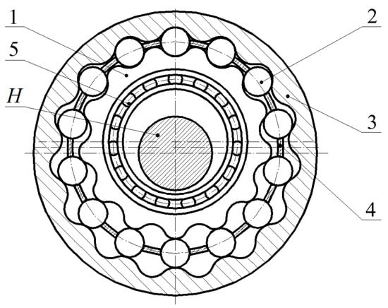
Figure 1.
Cross-section of a transmission with intermediate rolling elements and a free cage: H—generator; 1—cam; 2—intermediate rolling elements; 3—ring; 4—cage; 5—bearing.
2. Materials and Methods
After measuring the root diameters of the cycloid profiles of wheels manufactured by the OOO “Siberian Engineering Company”, it was found that the equipment allowed the obtainment of cycloid profiles with a normal distribution of dimensions that were approximately within the tolerance zone, as shown in Figure 2. The distribution of the results of measuring the diameter of the disk roots (Figure 2) does not exactly conform to the normal distribution law but can be approximately taken as such, owing to the insignificant deviation of the presented distribution from the normal law. The cycloid profile with a root diameter of Ø175 mm was measured (the accuracy was according to the 7th tolerance grade). The diameter was measured using the contact method with a clock-type indicator. The data on five pivot points were obtained in the root of the profile. Among these points, the point with the largest modulus coordinate was found. The measurements were also performed in the diametrically opposite root. The obtained diameter of the roots of the cycloidal profile was determined by the difference in the obtained coordinates. The diagram shows that the equipment processes the maximum number of parts according to the dimensions, the accuracy of which shifts to the upper limit of the tolerance zone from its centre. In this way, it is possible to determine the limits within the tolerance zone, to which more than 80% of the dimensions fall. When determining the permissible manufacturing clearance, one should focus on this range. Based on the measurement results (Figure 2), the following limits can be accepted within the tolerance zone: from 0.262 mm to 0.288 mm. Overall, 65% of the entire tolerance zone, that is 80% of the dimensions, obtained on the equipment are distributed approximately within two thirds of the tolerance zone per dimension.
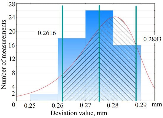
Figure 2.
Diagram of deviation distribution of the root diameter of the cycloid profile within the tolerance zone, TD = 0.04 mm.
We considered the normal law of the probability distribution for the obtained dimensions and the method of incomplete interchangeability when selecting fits for parts in the cycloid engagement.
In considering the engagement of a transmission with intermediate rolling elements and free cage (IREFC) (Figure 3), this consists of a wheel with an external cycloid profile—cam 1, cylindrical rolling elements 2 and a wheel with an internal cycloid profile—ring 3 [16,22].
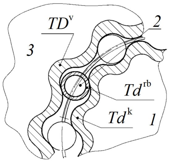
Figure 3.
Engagement of a transmission with IREFC and tolerance zones of dimensions of link contacting surfaces: 1—cam; 2—intermediate rolling elements; 3—ring.
As previously noted, when manufacturing contacting profiles of transmission links, the resulting dimensions are in the range of the tolerance zones (Figure 3). For cam 1 and rolling elements 2, they are made smaller than the nominal dimension and for ring 3, they are made larger than the nominal dimension. In fact, the dimensions of these three links can be manufactured in any combination but there is the possibility of manufacturing parts with dimensions using extreme tolerance values (Figure 4).
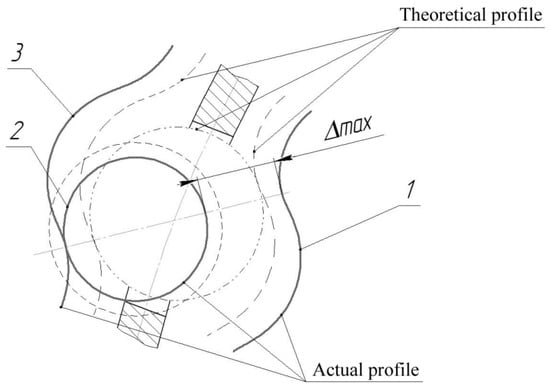
Figure 4.
Diagram of the link position in the cycloid tooth system of a transmission with IREFC when manufactured with the maximum possible clearance: 1—cam; 2—intermediate rolling elements; 3—ring.
Having considered the case presented in Figure 4, let us determine the maximum possible manufacturing clearance in the engagement of a transmission with IREFC using the following expression:
where TDv is the deviation tolerance of the diametric dimension of the ring profile;
Tdrb is the deviation tolerance of the diametric dimension of the rolling elements;
Tdk is the deviation tolerance of the diametric dimension of the cam profile.
Formula (1) describes the case where the contact surfaces of the ring are carried out according to the upper deviation and the contact surfaces of the rolling elements and the cam are carried out according to the lower one. However, the probability of such an event is extremely small and it is more likely that all parts will be manufactured according to the upper () tolerance value (Figure 5a) or according to the lower () value (Figure 5b).

Figure 5.
Cases of emergence of maximum manufacturing clearances in the engagement of a transmission with IREFC: 1—cam; 2—intermediate rolling elements; 3—ring; (a) maximum upper clearance; (b) maximum lower clearance.
In this case, the maximum manufacturing clearance in the engagement, using the agreed notations of deviations [23], can be determined as follows:
To manufacture all contacting parts according to the upper deviation
To manufacture all contacting parts according to the lower deviation
The tolerance value is substituted into Formula (1) with a sign corresponding to the area of its location relative to the zero line. For example, if a hole with a tolerance by H is considered, then the tolerance in Formula (1) is substituted with the sign “+” and for the shaft by the same tolerance grade, with the sign “−”. Formulas (1)–(3) can be used to determine the clearance in the engagement of any cycloidal gearing with IRE. These equations take into account the actual shape of the contacting surfaces of the transmission links, i.e., the shape that is obtained after manufacturing these surfaces using the manufacturing equipment. In Formulas (2) and (3), deviations are substituted with their own signs. Expressions (1)–(3) are applicable for any fits; the exceptions are fits J and Js because their deviations are located on both sides of the zero line. When using these fits, the upper deviation for the hole and the lower deviation for the shaft should be substituted in Formula (1).
3. Results
At the manufacturing site, the contacting profile surfaces of the ring and cam are currently manufactured using the 7th tolerance grade with a fit of H (h), and the intermediate rolling elements with h6. For the engagement with a rolling element diameter of 12 mm and the root diameters of the ring of 175 mm and the cam diameter of 151 m by the specified fits and tolerance grades, the deviations will be as follows:
Ø175H7 − TD = 40 µm; Ø151h7 − TD = 40 µm; Ø12h6 − TD = 11 µm.
Having performed the calculation according to Formula (1), let us determine the maximum manufacturing clearance for such engagement as being ∆max = 51 µm. According to Formulas (2) and (3), the clearance limits for the engagement under consideration will be equal to = 20 µm and = 31 µm. In this way, the transmissions with IRE that are currently manufactured at enterprises have a clearance in the engagement changing from 0.02 to 0.05 mm. Therefore, investigating combinations of fits with coarser tolerance grades lets us determine such combinations in which the manufacturing clearances will be in a mentioned range or less. It should be noted that during manufacturing, the dimension distribution within the tolerance zone is uneven.
Let us study the combination of fits on the contacting parts of transmissions with intermediate rolling elements and free cage (IREFC) to determine the minimum clearance limits in the selected accuracy range. When considering this further, for notational convenience of the engagement with a combination of fits and tolerance grades, let us make the fit and the tolerance grade of the ring a priority. Then, those of the rolling elements follow and finally, those of the cam. For example, for the case under consideration, let us designate the engagement as H7-h6-h7. The analysis of Formulas (1)–(3) shows that for a combination of H-h-h fits, when increasing the tolerance grade (substituting for a coarser one), the manufacturing clearances in the engagement will only increase. Therefore, it is worth considering other combinations of fits. It should also be noted that changing the accuracy of the diameter of the rolling elements is not always justified. Currently, the manufacture of cylindrical or spherical rolling elements with an accuracy of h6 has been launched into mass production and such parts can be purchased for less than the expenditures for manufacturing a small lot at one’s own manufacturing site, even with less accuracy.
Further, in this way, let us use the h6 fit for the rolling elements and consider the combinations of fits with coarser tolerances, only for profile cycloid disks.
Let us take into consideration several combinations of fits: H-h-k; K-h-h; Js-h-h; H-h-js; K-h-js; Js-h-k. The deviation values will be used for the following diameters: outer profile disk—Ø127.8 mm; rolling elements—Ø18 mm; internal profile disk—Ø82.5 mm. For the considered combinations of fits, the change in the tolerance grade, varying from the 7th to the 9th for cycloid disk fits, has been studied (Table 1).

Table 1.
Values of manufacturing clearances when changing the tolerance grade and combination of fits.
The results, obtained using expressions (1)–(3), are conveniently presented in graphic form (Figure 6, Figure 7 and Figure 8).
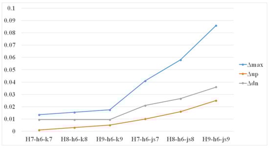
Figure 6.
Change of the clearances in the engagement when manufacturing the external profile disk by the H fit.
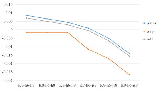
Figure 7.
Change of the clearances in the engagement when manufacturing the external profile disk by the K fit.
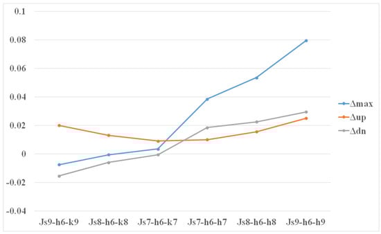
Figure 8.
Change of clearances in the engagement when manufacturing the external profile disk by the Js fit.
4. Discussion
The diagrams (Figure 6) demonstrate that when manufacturing the ring using the H9 fit and the cam using k9, the manufacturing clearance for transmissions with intermediate rolling elements and free cage (IREFC) varies from 0.005 mm to 0.017 mm. This is less than the clearance that emerges in the engagement when manufacturing profile disks, according to the 7th tolerance grade, as is carried out at enterprises. Such fits can be assigned to the cycloidal profiles of the disks if other options are not considered. Manufacturing the cam profile with the js9 fit results in the obtainment of a manufacturing clearance ranging from 0.025 mm to 0.086 mm. This exceeds the parameters currently provided at the manufacturing site and is not acceptable.
In this case, it is important to bear in mind that the obtained clearance ranges represent the field of a possible location of real profiles of cycloidal wheels and the rolling elements. At the same time, the cycloidal surfaces of the disks and the cylindrical surface of the rolling elements are not equidistant from their theoretical profile.
When manufacturing the ring with the K9 fit and the cam with h9 (Figure 7), the manufacturing clearance for transmissions with IREFC changes from −0.001 mm to 0.004 mm. This is also less than the clearance currently obtained at enterprises when manufacturing profile disks according to the 7th tolerance grade. However, the minimum value of the clearance has turned out to have a “−” sign, that is a negative allowance may form instead of a clearance in the engagement. However, for the combination of fits under study, this is admissible since the negative allowance is 1 µm and can be eliminated during the mechanism roll-on due to roughness crumpling. If the cam is manufactured with the js9 fit, then instead of the clearance, it is possible to obtain only a negative allowance that can be sufficiently large, varying from −0.014 mm to −0.026 mm, which is not acceptable.
Figure 8 shows that the manufacture of the ring with the Js fit does meet the purpose of the research. First, in this case, a large negative allowance of up to 0.015 mm can arise. Second, a very large clearance of up to 0.079 mm may appear.
In this way, to design and manufacture cycloid profile disks, it is possible to recommend K9 fits for the ring, h9 for the cam and h6 for the rolling elements. In case of such a combination of fits, the transmission accuracy increases since there is the possibility of the emergence of an insignificant negative allowance. Such combination of fits decreases the clearance in the engagement, even compared to the more precise manufacture of profile disks. However, if the dimension distribution law within the tolerance zone is considered when manufacturing these disks, then 90% of the parts will be produced without a negative allowance and this will provide a more precise engagement of transmissions with IREFC.
The considered results are related to the accuracy of the manufacturing of the surfaces of parts that contact and create the engagement of transmissions with intermediate rolling elements (IRE). At the same time, the mutual bracing of these surfaces can be different. The cycloidal surfaces of the disks must theoretically be parallel to the cylindrical surface of the rolling elements. In fact, these surfaces may not be parallel to each other. The problem of studying the mutual bracing of the surfaces of parts in the engagement of transmissions with IRE seems to be an interesting task for further research.
5. Conclusions
It has been shown that in the case of different combinations of fits of the mating parts in transmissions with intermediate rolling elements and free cage (IREFC), both a clearance and a negative allowance can occur in the engagement. At the same time, when manufacturing parts according to the 9th accuracy tolerance grade, clearances of up to 0.086 mm (H9-h6-js9) and negative allowances of up to 0.026 mm (K9-h6-js9) may occur in the engagement. It is obvious that it is not expedient to assign the Js (js) fit to the cycloidal profiles of parts. However, it is possible to select such a combination of fits according to the 9th tolerance grade (K9-h6-h9), by which the clearance in the engagement changes from −0.001 mm to 0.003 mm. Furthermore, taking into account the machine settings, this clearance will vary from 0 mm to 0.003 mm. This fact will allow the provision of high transmission accuracy, in the case of low accuracy of the manufacturing of the relevant parts. This combination of fits should be used for any transmission with intermediate rolling elements (IRE). Moreover, in general, for complex combinations of structural joints, having three or more elements in simultaneous contact, it is possible to recommend the designation of fits with K for mated holes and with h for mated shafts.
Further development of the presented scientific results will allow qualitative improvement in transmission design and significantly facilitate the process of technological preparation for the production of gearing, which will subsequently allow the achievement of high technical and economic indicators in general. Also, the study of the problem of the mutual bracing of the surfaces of parts in the engagement of transmissions with IRE is promising.
Author Contributions
Conceptualization and methodology, E.A.E.; validation and formal analysis, A.D.E. and E.A.E.; investigation, V.Y.S.; resources, M.V.G.; data curation, A.V.O.; writing—original draft preparation, V.Y.S., M.V.G.; writing—review and editing, V.Y.S., N.V.M.; visualization, A.V.O.; supervision, E.A.E.; project administration, N.V.M. All authors have read and agreed to the published version of the manuscript.
Funding
This research was supported by the TPU development program.
Institutional Review Board Statement
Not applicable.
Informed Consent Statement
Not applicable.
Conflicts of Interest
The authors declare no conflict of interest.
References
- Belyaev, A.E. Mechanical Transmissions with Ball Intermediate Elements; Tomsk Polytechnic University: Tomsk, Russia, 1992. [Google Scholar]
- Pankratov, E.N. Design of Mechanical Systems of Automated Complexes in the Machining Production: Workshop of the Leader-Designer; Tomsk State University: Tomsk, Russia, 1998. [Google Scholar]
- Lustenkov, M.E. Criteria for the strength of mechanical transmissions with constituent intermediate rolling elements. Bull. Belarusian-Russ. Univ. 2015, 49, 33–41. [Google Scholar]
- Chen, B.; Fang, T.; Li, C.; Wang, S. Gear geometry of cycloid drives. Sci. China Ser. E Technol. Sci. 2008, 51, 598–610. [Google Scholar] [CrossRef]
- Mihailidis, A.; Athanasopoulos, E.; Agouridas, K. EHL film thickness and load dependent power loss of cycloid reducers. Mech. Eng. Sci. 2016, 230, 1303–1317. [Google Scholar] [CrossRef]
- Pokatilov, D.A.; Efremenkov, E.A. Analysis of the technological process of manufacturing the cycloid profile of transmission parts with intermediate rolling elements. Proc. Samara Sci. Cent. RAS 2015, 17, 868–873. [Google Scholar]
- Zhang, T.; Li, X.; Wang, Y.; Sun, L. A Semi-Analytical Load Distribution Model for Cycloid Drives with Tooth Profile and Longitudinal Modifications. Appl. Sci. 2020, 10, 4859. [Google Scholar] [CrossRef]
- Li, T.; An, X.; Deng, X.; Li, J.; Li, Y. A New Tooth Profile Modification Method of Cycloid Gears in Precision Reducers for Robots. Appl. Sci. 2020, 10, 1266. [Google Scholar] [CrossRef]
- Wang, H.; Shi, Z.-Y.; Yu, B.; Xu, H. Transmission Performance Analysis of RV Reducers Influenced by Profile Modification and Load. Appl. Sci. 2019, 9, 4099. [Google Scholar] [CrossRef]
- Hu, Y.; Li, G.; Zhu, W.; Cui, J. An Elastic Transmission Error Compensation Method for Rotary Vector Speed Reducers Based on Error Sensitivity Analysis. Appl. Sci. 2020, 10, 481. [Google Scholar] [CrossRef]
- Kočiško, M.; Pollák, M.; Töröková, M.; Baron, P.; Paulišin, D.; Kundrík, J. Determination of Methodology and Research of the Influence of the Trial Run of High-Precision Reducers on the Change of Their Characterizing Properties. Appl. Sci. 2021, 11, 3859. [Google Scholar] [CrossRef]
- Lustenkov, M.E. Transmissions with Intermediate Rolling Elements: Definition and Minimization of Power Losses; Belarusian-Russian University: Mogilev, Belarus, 2010. [Google Scholar]
- Kan, A. Distribution of efforts between the links of the planetary gearing of the k-h-v type. Bull. Mech. Eng. 2016, 5, 60–63. [Google Scholar]
- Kan, A.; Il’In, A.S.; Lazurkevich, A.V. Load analysis of the planetary gear train with intermediate rollers. Part 2. IOP Conf. Ser. Mater. Sci. Eng. 2016, 124, 012004. [Google Scholar] [CrossRef]
- Lustenkov, M.E. Strength calculations for cylindrical transmissions with compound intermediate rolling elements. Int. J. Mech. Robot. Syst. 2015, 2, 111–121. [Google Scholar] [CrossRef]
- Efremenkov, E.A.; Kobza, E.E.; Efremenkova, S.K. Force Analysis of Double Pitch Point Cycloid Drive with Intermediate Rolling Elements and Free Retainer. Appl. Mech. Mater. Sci. J. 2015, 756, 29–34. [Google Scholar] [CrossRef]
- Li, T.; Tian, M.; Xu, H.; Deng, X.; An, X.; Su, J. Meshing contact analysis of cycloidal-pin gear in RV reducer considering the influence of manufacturing error. J. Braz. Soc. Mech. Sci. Eng. 2020, 42, 1–14. [Google Scholar] [CrossRef]
- Lustenkov, M.E. Evaluation of the resource and the load capacity of transmissions with constituent intermediate elements. Top. Quest. Mach. Sci. Collect. Rescuers Paper 2014, 3, 189–191. [Google Scholar]
- Chen, B.; Zhong, H.; Liu, J.; Li, C.; Fang, T. Generation and investigation of a new cycloid drive with double contact. Mech. Mach. Theory 2012, 49, 270–283. [Google Scholar] [CrossRef]
- Bao, J.; He, W. Parametric Design and Efficiency Analysis of the Output-Pin Wheel Cycloid Transmission. International. J. Control Autom. 2015, 8, 349–362. [Google Scholar] [CrossRef]
- Meng, Y.; Wu, C.; Ling, L. Mathematical modeling of the transmission performance of 2K–H pin cycloid planetary mechanism. Mech. Mach. Theory 2007, 42, 776–790. [Google Scholar] [CrossRef]
- Efremenkov, E.A.; I-Kan, A. Euler-Savari Determination of Radii of Curvature of Cycloid Profiles. Russ. Eng. Res. 2010, 30, 1001–1004. [Google Scholar] [CrossRef]
- Myagkov, V.D. Tolerances and Fits; Reference book. In 2 parts. 6th rev.; Mechanical Engineering: Leningrad, Russia, 1982. [Google Scholar]
Publisher’s Note: MDPI stays neutral with regard to jurisdictional claims in published maps and institutional affiliations. |
© 2021 by the authors. Licensee MDPI, Basel, Switzerland. This article is an open access article distributed under the terms and conditions of the Creative Commons Attribution (CC BY) license (https://creativecommons.org/licenses/by/4.0/).