Article

Analysis of Tunnel Water Inrush Considering the Influence of Surrounding Rock Permeability Coefficient by Excavation Disturbance and Ground Stress

1
School of Civil Engineering, Central South University, Changsha 410075, China
2
National Engineering Laboratory of High-Speed Railway Construction Technology, Central South University, Changsha 410075, China
3
Guangdong Nanyue Transportation Investment and Construction Co., Ltd., Guangzhou 510101, China
*
Author to whom correspondence should be addressed.
Appl. Sci. 2021, 11(8), 3645; https://doi.org/10.3390/app11083645
Submission received: 16 March 2021 / Revised: 14 April 2021 / Accepted: 16 April 2021 / Published: 18 April 2021

Abstract

:
Affected by the coupling of excavation disturbance and ground stress, the heterogeneity of surrounding rock is very common. Presently, treating the permeability coefficient as a fixed value will reduce the prediction accuracy of the water inflow and the external water pressure of the structure, leading to distortion of the prediction results. Aiming at this problem, this paper calculates and analyzes tunnel water inflow when considering the heterogeneity of permeability coefficient of surrounding rock using a theoretical analysis method, and compares with field data, and verifies the rationality of the formula. The research shows that, when the influence of excavation disturbance and ground stress on the permeability coefficient of surrounding rock is ignored, the calculated value of the external water force of the tunnel structure is too small, and the durability and stability of the tunnel are reduced, which is detrimental to the safety of the structure. Considering the heterogeneity of surrounding rock, the calculation error of water inflow can be reduced from 27.3% to 13.2%, which improves the accuracy of water inflow prediction to a certain extent.

1. Introduction

For deep-buried mountain tunnels in rich water areas, if design or construction is improper, groundwater will continue to pour into a tunnel throughout its construction and operation period, destroying the surface environment and affecting the durability and stability of the tunnel structure [1,2,3,4,5].Considering factors such as structural safety and ecological environment, tunnels in high water level areas mostly adopt the waterproofing and drainage design criteria of “mainly blockage, limited discharge” [6,7,8]. Presently, the prediction of tunnel water inflow and the calculation of structural external water pressure are very important for the design of waterproofing and drainage of deep-buried mountain tunnels in high water level areas. The permeability coefficient is an important factor that affects prediction accuracy. Surrounding rock is often heterogeneous due to the coupling of ground stress and excavation disturbances; therefore, studying the influence of surrounding rock heterogeneity on tunnel water inrush has important theoretical significance and engineering application value.
The literature [9,10,11,12,13,14,15,16] regards the permeability coefficient of surrounding rock as a fixed value, and has deduced the calculation formula of tunnel water inflow, analyzed the water blocking mechanism of a grouting circle, and provided a theoretical basis for the design of the grouting circle. In the research on the influence of the heterogeneity of surrounding rock on water inrush in a tunnel, Reference [17] considered the water gushing condition of a tunnel when complex hydrogeology is involved. The authors of [18] calculated the influence of changes in hydraulic conductivity on the calculation of inrush water. Reference [19] derived a calculation formula of water inflow for underwater tunnels based on the constructed water inflow calculation model. The authors of [20] analyzed the damage of surrounding rock induced by engineering disturbances and their influence on the permeability of rock mass. Assuming that the permeability coefficient of a damage zone is a fixed value, the influence of the change in the surrounding rock structure on tunnel water inrush and external water pressure were studied using a theoretical analysis method.
In summary, scholars have conducted extensive research on the prediction of water inflow and external water pressure, but the prediction methods are all based on the premise of homogeneous or layered homogeneity of the surrounding rock. In actual engineering, the permeability coefficient of surrounding rock is often affected by excavation disturbance and ground stress, and presents heterogeneity, it also changes gradually with spatial position coordinates. Based on this, this paper considers the spatial dispersion of the permeability coefficient of surrounding rock with the influence of depth and excavation disturbance, and constructs a one-dimensional seepage calculation model in the vertical section. The calculation formula for the water inflow and the structural head was derived and carried out for degradation verification, in order to make meaningful attempts to supplement the prediction and calculation methods of the water inflow and the external water pressure of the structure.

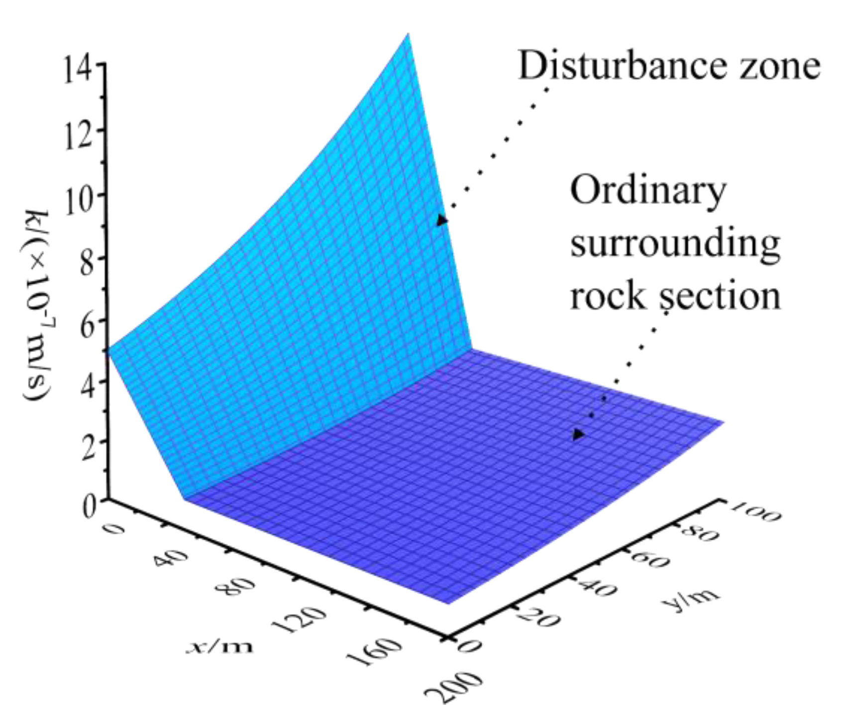
2. Permeability Calculation Model

The permeability coefficient is an index that comprehensively reflects the permeability of surrounding rock, and the correct determination of its value is of great significance to the calculation of water gushing. The literature [21,22] shows that, under the influence of in situ stress, the pore structure of surrounding rock continuously decreases with the increase of in situ stress, and the permeability coefficient of surrounding rock generally decays in a negative exponential curve with burial depth. At the same time, surrounding rock is damaged by excavation and produces a disturbance zone. The literature [23,24,25,26] found that the permeability of surrounding rock in the disturbance zone will increase by orders of magnitude after a tunnel is excavated via field measurement of the permeability of the surrounding rock of a tunnel. According to the authors of [27], it is assumed that the permeability coefficient of surrounding rock in a disturbance zone changes linearly and gradually with the radial distance from the tunnel. The spatial expression of the permeability coefficient of the surrounding rock on one side of a tunnel is:
k = { m e n y                  x > l + t ; l < x < l + t , y > t ( m 0 + a x ) e n y    l < x < l + t , 0 < y < t
m 0 is the equivalent permeability coefficient of the tunnel axis position affected by the excavation disturbance; n reflects the variability of the permeability coefficient of surrounding rock under the influence of ground stress; a reflects the variability of the permeability coefficient of the surrounding rock under the influence of excavation disturbance.
Based on this, considering the coupling effects of ground stress and excavation disturbance, a simplified spatial model of the permeability coefficient of the surrounding rock is established, as shown in Figure 1.
In Figure 1, the length of the disturbance zone is AB , the width is AD , and the radial distance between the edge of the disturbance zone and the tunnel is l .
It is assumed that the buried depth of the tunnel is 100 m ; the equivalent permeability coefficient of the tunnel axis position affected by excavation disturbance is 5 × 10 8 m / s ; the permeability coefficient of the undisturbed zone is 10 8 m / s ; the coefficient of variation of the permeability coefficient of the surrounding rock under the influence of in situ stress is 0.01. The distribution of permeability coefficient of surrounding rock within 200 m horizontal distance from the tunnel is shown in Figure 2.

3. Theoretical Calculation and Result Verification

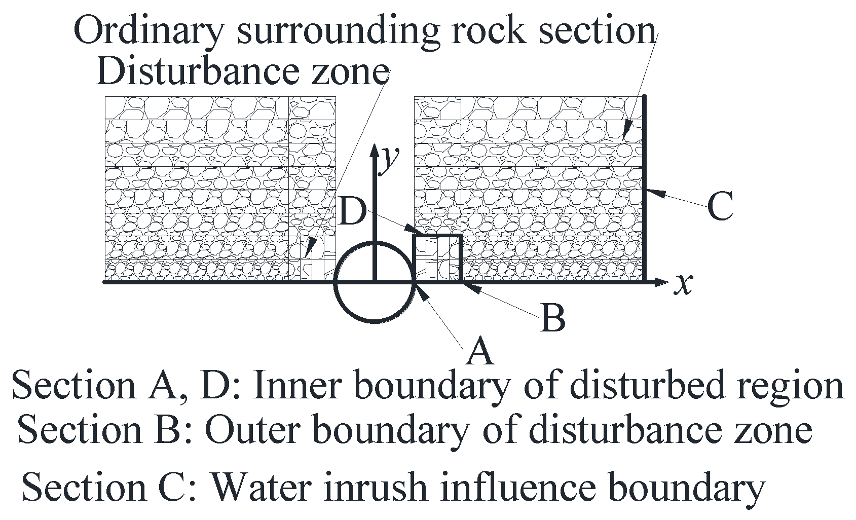
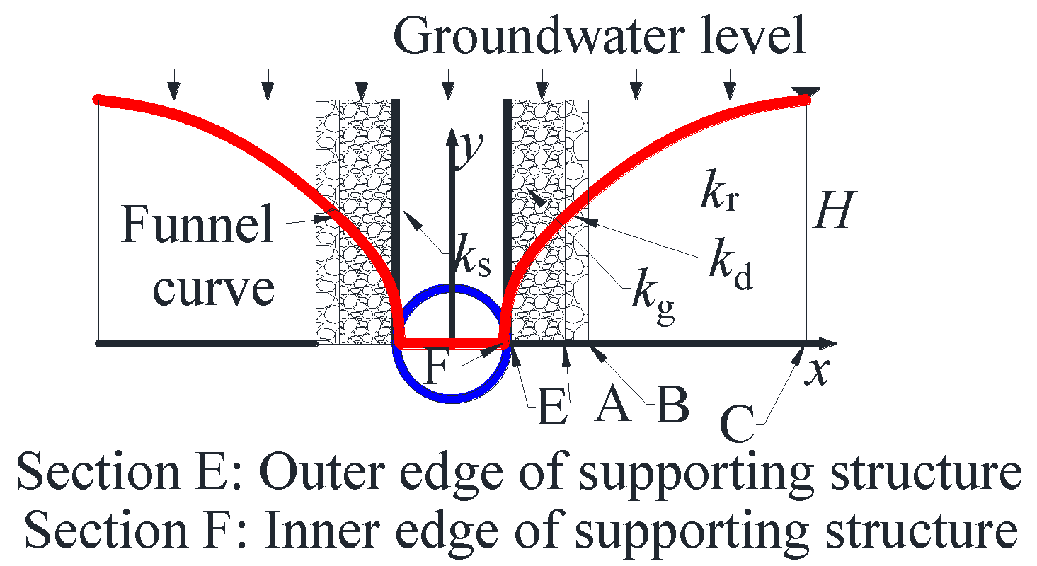
3.1. Establishment of Water Gushing Model

During the construction of a tunnel, drainage of groundwater will cause the groundwater level to drop and damage the ecological environment of the tunnel site. After a long period of constant flow pumping, the diving surface forms a relatively stable drop funnel near the tunnel, with a shape similar to an inverted cone [28,29].
Assuming that the initial water level is H, the inner and outer diameters of the tunnel support structure are r0 and r1, the thickness of the grouting reinforcement ring is lr1, and the tunnel seepage volume is q, when seepage is stable. When tunnel drainage is stable, the diving flow can be regarded as a steady flow. Ignoring replenishment along the tunnel axis, the phreatic flow can be regarded as a one-dimensional flow, and the tunnel drainage calculation model is established, as shown in Figure 3.
In Figure 3, C shows the position of the influence radius in the tunnel cross section when seepage is stable; B , A , E and F , respectively, indicate the outer edge of the disturbance zone in the tunnel cross section, the outer edge of the grouting ring, the outer edge of the supporting structure and outer edge of supporting structure and inner edge of supporting structure. Areas FE , EA , AB and BC represent the supporting structure, grouting circle, disturbance zone and ordinary surrounding rock section, respectively, and the permeability coefficients of each area are k s , k g , k d and k r , respectively. Among them, areas FE and EA are regarded as homogeneous media without considering the discrete type of permeability coefficient; area AB is a disturbance zone, and the permeability coefficient of surrounding rock is affected by two factors of excavation disturbance and in situ stress; area BC is only affected by in situ stress. The surrounding rock is considered to be layered and homogeneous, and the permeability coefficient increases with the increase in the vertical distance from the tunnel. The permeability coefficient of the surrounding rock in section AB and BC is determined by Equation (1).

3.2. Calculation of Water Pressure outside the Structure

According to the theory of groundwater mechanics, when seepage is stable, the expression of the seepage differential equation is [30,31]
d d x ( k h d h d x ) + w = 0
In Formula (2), k is the medium permeability coefficient; w is the vertical infiltration replenishment strength at the top of the tunnel; and h is the head height of any section x .
According to the simplified calculation model established in Figure 3, using boundary conditions, the head pressure of each area is calculated in turn.

3.2.1. Area FE

Area FE is a supporting structure with a fixed permeability coefficient. It is assumed that the height of the water head at the inner edge of the supporting structure is h F . It can be seen from Figure 3 that the abscissas of the section and location are r 0 , r 1 , respectively. The seepage volume from supporting structure F into the tunnel at the section is q 2 r 0 w , then the region FE seepage differential equation is
  k s d d x ( h d h d x ) + w = 0 q 2 w r 0 = k s h d h d x | x r 0   h | x r 0 = h F }
The solution is
h 2 = w k s x 2 + q k s x + w r 0 2 q r 0 k s + h F 2
Then, the head height at section E is expressed as
h E 2 = r 1 r 0 k s ( q w ( r 1 + r 0 ) ) + h F 2

3.2.2. Area EA

Area EA is a grouting structure, the permeability coefficient is fixed, the cross-section E and the abscissa A are r 1 and l , respectively, and the seepage volume from grouting structure E into the tunnel support structure at the cross-section is: q 2 r 1 w , then, the seepage of EA region differential equation is
  k g d d x ( h d h d x ) + w = 0 q 2 w r 1 = k g h d h d x | x r 1   h | x r 1 = h E }
then the solution is
h 2 = w k g x 2 + q k g x + w r 1 2 q r 1 k g + h E 2
Combining Equations (5) and (7), the head expression of region EA is
h 2 = w k g x 2 + q k g x + w r 1 2 q r 1 k g + r 1 r 0 k s ( q w ( r 1 + r 0 ) ) + h F 2
Furthermore, the expression of the water head at the outer edge of the grouting circle h A is calculated as
h A 2 = l r 1 k g ( q w ( l + r 1 ) ) + r 1 r 0 k s ( q w ( r 1 + r 0 ) ) + h F 2

3.2.3. Area AB

Area AB is the excavation disturbance area, and the permeability coefficient is affected by the coupling of excavation disturbance and ground stress. Combining Formulas (1) and (2) together, the regional seepage differential equation of region AB is
0 h ( m 0 + a x ) e n y d h d x d y + w x = q 2
The general solution of Equation (10) is
e n h n 2 h n = w a x + q a + 2 w m 0 2 a 2 ln ( a x + m 0 ) + C 1
Equation (11) is the integral constant. Using boundary A as the conditions at the section, the solution expression of C 1 is
C 1 = e n h A n 2 h A n + w a l q a + 2 w m 0 2 a 2 ln ( a l + m 0 )
Substituting Formula (12) into Formula (11), the head function expression of region AB is
e n h n 2 h n = w a x + e n h A n 2 h A n + w a l + q a + 2 w m 0 2 a 2 ln a x + m 0 a l + m 0
Then the expression of the head height at section B is
e n h B n 2 h B n = w a t + e n h A n 2 h A n + q a + 2 w m 0 2 a 2 ln a ( l + t ) + m 0 a l + m 0

3.2.4. Area BC

Area BC is the ordinary surrounding rock section A, the permeability coefficient is only related to the buried depth, and the seepage differential equation is
0 h m e n y d h d x d y + w x = q 2
The general solution of Equation (15) is
e n h n 2 h n = q 2 m x w 2 m x 2 + C 2
In Equation (16), C 2 is the parameter, which can be solved by the boundary conditions.
The boundary conditions at the section C
h C | x = q 2 w = H
Substituting Formula (17) into (16), the expression of C 2 is
C 2 = e n H n 2 H n q 2 8 m w
Substituting Formula (18) into Formula (16), the head function expression of calculation area BC is
e n h n 2 h n = q 2 m x w 2 m x 2 + e n H n 2 H n q 2 8 m w
Then, expression h B is
e n h B n 2 h B n = q 2 m ( l + t ) w 2 m ( l + t ) 2 + e n H n 2 H n q 2 8 m w

3.3. Calculation of Tunnel Water Inflow

Combining the vertical Formulas (14) and (20), the result obtained is
e n h A e n H n 2 h A H n + q a + 2 w m 0 2 a 2 ln a ( l + t ) + m 0 a l + m 0 = l + t 2 m [ q w ( l + t ) ] q 2 8 m w + w a t
Combining Equations (9) and (21), using the design or on-site measurement of the water head height of the inner edge of supporting structure h F , the expression of the tunnel water inflow q can be solved. At this time, the expression of water inflow q is an implicit transcendental equation, which is difficult to analytically solve. It can be obtained using numerical methods.

3.4. Degradation Analysis

Using Taylor series expansion theorem [32], the result is
e n h n 2 h n = 1 n 2 + 1 n i = 2 + n i 1 h i i !
Substituting Formula (22) into (19), the result is
1 n i = 2 + n i 1 h i i ! = q 2 m x w 2 m x 2 + 1 n i = 2 + n i 1 H i i ! q 2 8 m w
Equation (23) is the head function expression when only considering the permeability coefficient of surrounding rock affected by in situ stress. When n = 0 , m = k r Formula (23) degenerates into
h 2 = w x 2 k r + q x k r + H 2 q 2 4 k r w
Comparing Equation (24) with Equations (4) and (7), the difference between the three equations is only the permeability coefficient of each structure and the parabolic constant term. The structural permeability coefficient is determined by the properties of the three regions, and the constant term is determined by the boundary conditions. That is, Formula (23) can be degenerated into the head potential function expression without considering the permeability coefficient of the surrounding rock changing with the ground stress: (4) and (7), which verifies the rationality and correctness of the derivation to a certain extent.
Substituting Formula (22) into (14), the result is
1 n i = 2 + n i 1 h i i ! = w a x + 1 n i = 2 + n i 1 h A i i ! + w a l + q a + 2 w m 0 2 a 2 ln a x + m 0 a l + m 0
By using Taylor’s formula, then the results obtained are
ln ( x + 1 ) = i = 0 ( 1 ) i i + 1 x i + 1
Substituting Equation (26) into Equation (25), the result is
1 n i = 2 + n i 1 h i i ! = w a x + 1 n i = 2 + n i 1 h A i i ! + w a l + q a + 2 w m 0 2 a 2 i = 0 [ ( 1 ) i i + 1 ( a x a l a l + m 0 ) i + 1 ]
Equation (27) is the head function expression considering the permeability coefficient of surrounding rock is simultaneously affected by the coupling of excavation disturbance and ground stress. When a = 0 , m 0 = m , Formula (27) degenerates into
1 n i = 2 + n i 1 h i i ! = 1 n i = 2 + n i 1 h A i i ! x 2 2 m l 2 2 m + x l m
Comparing Equations (28) and (23), the difference between the two equations is only the symmetry axis of the parabola and the constant line, which is affected by the abscissa of the boundary and the height of the water head. Therefore, Equation (13) can be degenerated into Equation (19) that does not consider the influence of the surrounding rock permeability coefficient on excavation disturbance, and Equation (19) is the special working condition derived from Equation (13).
After degradation analysis, the head expression for the permeability coefficient of the surrounding rock as a fixed value is considered as the special case of this article considering the permeability coefficient of the surrounding rock is affected by the in-situ stress; The limit condition of the influence of ground stress and excavation disturbance on the permeability coefficient of surrounding rock verifies the correctness of the formula derivation in this paper to a certain extent.

4. Parameter Sensitivity Analysis

Assuming that the tunnel radius r 0 is 6 m , the thickness of the supporting structure is 0.8 m , the thickness of the grouting circle is 4 m , the permeability coefficient of the undisturbed zone of the surrounding rock at tunnel axis m is 5 × 10 8 m / s , and ratio m and k g is 20, and the ratio m and k s is 5, the initial water level H is 200 m , and the rainfall infiltration replenishment strength W is 0.0035 m / d . Based on the formula derived in Section 2, the influence of various relevant parameters on the height of the regional water head is analyzed.

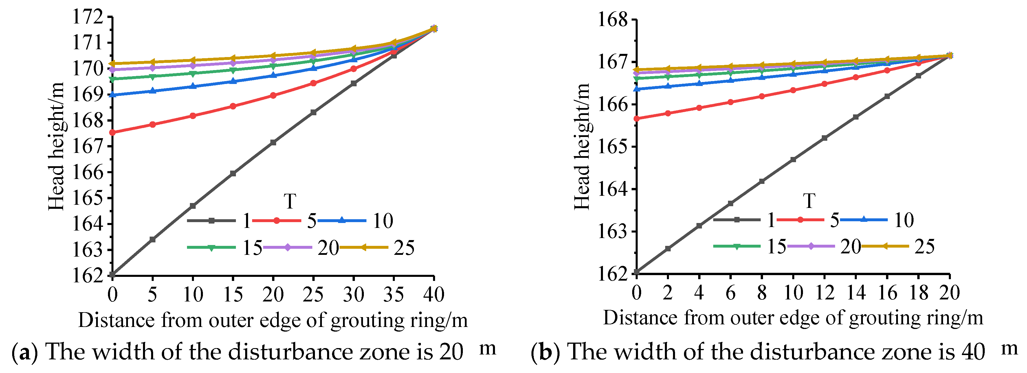
4.1. Influence of Excavation Disturbance on External Water Pressure of Structure

Assuming that the ratio of permeability coefficients between points A and B is T; the variation value of the permeability coefficient of the surrounding rock affected by the ground stress n is taken as 0.02; the water inflow q is 3 m 3 / d / m when the seepage is stable. Using Formulas (13) and (21), the water head at each position in the disturbance zone is calculated, and the curve is drawn in Figure 4.
Figure 4 shows that when considering the linear change of the permeability coefficient in the disturbance zone, the permeability coefficient of the water head in the disturbance zone increases, the water blocking capacity is weakened, and the head loss decreases, which leads to an increase in the head height of each section, but the sensitivity decreases with the increasing T.
Solve Equations (9) and (21) together, and calculate the water head height of the inner edge of the supporting structure h F , and the curve is shown in Figure 5.
Figure 5 shows that the water head height of the inner edge of the supporting structure first increases sharply with the increase of the parameters T, and then tends to be stable. When the excavation disturbance changes the permeability coefficient of the surrounding rock to an order of magnitude, the relationship between the water head height at the inner edge of the supporting structure and the degree of the permeability coefficient of the surrounding rock in the disturbance zone is weak. At the same time, the height of the water head at the inner edge of the supporting structure increases with the increase of the disturbance area.
When ignoring the influence of excavation disturbance on the permeability coefficient of surrounding rock, the calculated value of the water head height at the outer edge of the grouting ring and the inner edge of the supporting structure is too small. In the actual project, the tunnel structure is eroded by high water pressure for a long time, and the durability and stability are reduced. Therefore, the construction level should be improved, the degree of damage to the surrounding rock of the tunnel should be reduced, the radial damage distance to the surrounding rock should be reduced, and the thickness of the grouting ring can be appropriately increased when it is necessary to achieve the purpose of protecting the tunnel structure.

4.2. The Influence of Ground Stress on the External Water Pressure of the Structure

Using the parameters in Section 3.1., according to Formula (19), the water head at each position of the ordinary surrounding rock section is calculated, and the curve is drawn in Figure 6.
Figure 6 shows that the height of the water head at each position of the ordinary surrounding rock section increases with the increase of the permeability coefficient of the surrounding rock by the in situ stress variation parameter n . When the variation parameters n are ignored, the water blocking capacity of the surrounding rock is improved, the head loss is increased, and the structure is in a disadvantageous state.
Excavation disturbance, ground stress, tunnel support structure and grouting circle will all cause the permeability of surrounding rock to change to varying degrees, and then affect the water resistance of surrounding rock. The difference is that the excavation disturbance, the tunnel support structure and the grouting circle are artificially changed, and the in situ stress affects the original permeability coefficient of the surrounding rock. The influence of various factors on the permeability coefficient of surrounding rock should be considered in the design of tunnel supporting structure and waterproofing and drainage, so as to reduce the probability of prediction distortion.

5. Case Analysis

5.1. Engineering Background

The left and right holes of Hongtu Tunnel are 6336 m and 6337 m long respectively, the ground elevation is 245–1060 m , the design elevation of the tunnel bottom is 239–344 m , and the maximum buried depth is about 739 m . It is a deep-buried super long mountain tunnel. It is located in the Lianhuashan fault zone, Jixinshan fault, NW-trending fault, and Tongziyang syncline area affected by regional large faults, with violent folds and well-developed faults. There are 26 faults. At the same time, the Hongtu Tunnel is adjacent to Feiquan Power Station, Feiquan Reservoir, and Sandu Reservoir, and passes through Huangmian Lake Reservoir. Some faults are connected to large water bodies, and the risk of water inrush is extremely high, the topography of the whole section and the tunnel structure at the entrance section are shown in Figure 7.
Large water gushing occurred during the construction of the two sections of the tunnel, as shown in Figure 8. The average flow rate at the outlet end is 9592 m 3 / d , and the maximum flow rate is nearly 20,000 m 3 / d . During the construction process at the inlet end, the high-pressure water will top-down the down-the-hole drill, and the double-hole water inflow can be as high as 100,000 m 3 / d , as shown in Figure 9, and the starting position of the tunnel is k89–392.
An intelligent string-type digital piezometer is embedded in the initial support of the corresponding mileage pile number. The osmotic pressure measurement range is 1.0 MPa , and the sensitivity is 0.001 MPa . The on-site embedment and measurement are shown in Figure 10.

5.2. Parameter Selection

The curved wall tunnel section with inverted arch is closer to a circle. According to the literature [33], the tunnel section is assumed to be circular at this time, and the error is generally within an acceptable range. In this paper, the radius of the circumscribed circle of the tunnel section is taken as the equivalent circle radius, and the expression is [34]
r 0 = 4 h 2 + d 2 4 cos ( arc tan ( d 2 h ) )
In Formula (29), r 0 is the radius of the original tunnel after equal circle treatment; d is the cross-section span of the original tunnel; h is the cross-section height of the original tunnel.
In order to verify the correctness of the solution in this paper, a large area of water gushing in a certain section of the construction is selected for analysis. The calculated equivalent circle radius r 0 is 6.2 m . Comprehensive consideration of the initial support and secondary lining is 80 cm . There are few data on the influence of excavation disturbance on the permeability coefficient. The paper ignores the change of the permeability coefficient of the surrounding rock in the shallow buried section of the tunnel entrance with the buried depth is ignored, and the permeability coefficient of the surrounding rock is regarded as only related to the excavation disturbance. According to the measured water inrush data at the tunnel entrance, using Formulas (9) and (21), the numerical value of the influence of excavation on the permeability coefficient is inverted, and the numerical value is applied to the deep buried section. Combining the design institute and field test and construction experience, the values of each parameter are shown in Table 1. The permeability coefficient of the supporting structure takes the effects of the circumferential and longitudinal drainage pipes into account, and its value refers to the calculation method in References [35,36].

5.3. Result Analysis

Using the data in Table 1, simultaneously, Equations (9) and (21) calculate the theoretical water inflow to be 2.96 m 3 / d / m , and the measured water inflow to be 3.41 m 3 / d / m , with an error of 13.2%. If the influence of excavation disturbance and ground stress on the permeability coefficient of surrounding rock is not considered, the calculated theoretical water inflow is 2.48 m 3 / d / m , and the error from the actual measurement is 27.3%. That is to say, considering the influence of ground stress and excavation disturbance on the permeability coefficient of surrounding rock, the calculation error of water inflow can be reduced from 27.3% to 13.2%, which improves the accuracy of water inflow prediction and it verifies the rationality of the model constructed in this article and the correctness of the formula derivation to a certain extent. The prediction error is mainly caused by the approximate replacement of the equivalent circle and the actual seepage near the tunnel is a two-dimensional flow, which is caused by ignoring the vertical seepage in the calculation.

6. Conclusions

Considering the influence of excavation disturbance and in-situ stress, a space progressive dispersion model of the permeability coefficient of surrounding rock is constructed, and the calculation formulas for water inflow and external water pressure of the structure are derived, and the analytical formulas are degraded and verified by using Taylor formula and series expansion theorem. Finally, the correctness of the model and formula derivation is verified by comparing with the field measured data. The specific conclusions are:
  • The calculation expressions for the water inflow and the external water pressure of the structure are derived when considering the heterogeneity of the surrounding rock, and the calculation results can be degenerated into the calculation expressions for the water inflow and the external water pressure of the structure when the permeability coefficient is fixed;
  • When ignoring the excavation disturbance and the influence of ground force, the calculated value of the water head height assumed by each structure is too small, which is not good for the safety of the structure;
  • Through the analysis of calculation examples, considering the influence of excavation disturbance and ground stress on the permeability coefficient of surrounding rock, the prediction accuracy of water inflow can be improved. The influence of various factors on the permeability coefficient of surrounding rock should be considered in the design of tunnel supporting structure and waterproofing and drainage, so as to reduce the probability of prediction distortion.

Author Contributions

Conceptualization, H.F. and P.A.; methodology, H.F., PA. and L.C. validation, G.C., J.L. and X.Y.; writing—original draft preparation, P.A.; writing—review and editing, H.F. All authors have read and agreed to the published version of the manuscript.

Funding

This research was funded by the research on the damage mechanism and performance recovery of carbon phyllite in the basement of high-speed railway tunnel in cold region (51978668) and the key technology of green construction of Hongtu extra tunnel (DFH (201904) ys1-001). The authors want to acknowledge these financial assistances.

Acknowledgments

This paper is sponsored by the research on the damage mechanism and performance recovery of carbon phyllite in the basement of a high-speed railway tunnel in a cold region (51978668) and the key technology of the green construction of the Hongtu extra tunnel (DFH (201904) ys1–001). The authors want to acknowledge this financial assistance.

Conflicts of Interest

The authors declare no conflict of interest.

References

  1. Kolymbas, D.; Wagner, P. Groundwater ingress totunnels-the exact analytical solution. Tunn. Undergr. Space Technol. 2007, 22, 23–27. [Google Scholar] [CrossRef]
  2. Hwang, J.H.; Lu, C.C. A semi-analytical method for analyzing the tunnel water inflow. Tunn. Undergr. Space Technol. 2007, 22, 39–46. [Google Scholar] [CrossRef]
  3. Wang, X.Y.; Tan, Z.S.; Wang, M.S.; Zhang, M. Analysis of interaction between surrounding rock and lining in high water-level tunnels with controlled drainage. Rock Soil Mech. 2008, 29, 1623–1628. [Google Scholar]
  4. Fan, H.; Zhang, Y.; He, S.; Wang, K.; Wang, X.; Wang, H. Hazards and treatment of karst tunneling in Qinling-Daba mountainous area: Overview and lessons learnt from Yichang–Wanzhou railway system. Environ. Earth Sci. 2018, 77, 679. [Google Scholar] [CrossRef]
  5. Sun, Z.; Zhang, D.; Fang, Q. Determination Method of Reasonable Reinforcement Parameters for Subsea Tunnels Considering Ground Reinforcement and Seepage Effect. Appl. Sci. 2019, 9, 3607. [Google Scholar] [CrossRef] [Green Version]
  6. Wang, X.; Wang, M.; Zhang, M. Research on regulating water pressure acting on mountain tunnels by block ground water and limiting discharge. Chin. J. Geotech. Eng. 2005, 27, 125–127. [Google Scholar]
  7. Tao, X.L.; Ma, J.R.; Zeng, W. Treatment effect investigation of underground continuous impervious curtain application in water-rich strata. Int. J. Min. Sci. Technol. 2015, 25, 975–981. [Google Scholar] [CrossRef]
  8. Sembenelli, P.G.; Sembenelli, G. Deep jet-grouted cut-offs in riverine alluvia for ertan cofferdams. J. Geotech. Geoenviron. Eng. 1999, 125, 142–153. [Google Scholar] [CrossRef]
  9. Li, P.; Wang, F.; Long, Y.; Zhao, X. Investigation of steady water inflow into a subsea grouted tunnel. Tunn. Undergr. Space Technol. 2018, 80, 92–102. [Google Scholar] [CrossRef]
  10. Yang, S.; He, C.; Li, Z. Inner water pressure distribute on law of tunnel grouting circle in water-rich area. J. China Univ. Min. Technol. 2017, 46, 546–553. [Google Scholar]
  11. Pan, Y.H.; Luo, Q.Q.; Zhou, B.; Chen, J.P. Analytical study on seepage field of deep tunnel with grouting circle in half plane. J. Zhejiang Univ. (Eng. Sci.) 2018, 52, 1114–1122. [Google Scholar]
  12. Zhang, D.; Fang, Q. Grouting techniques for the unfavorable geological conditions of Xiang’an subsea tunnel in China. J. Rock Mech. Geotech. Eng. 2014, 6, 438–446. [Google Scholar] [CrossRef]
  13. Zhang, D.; Sun, Z. An active control waterproof and drainage system of subsea tunnels and its design method. Chin. J. Rock Mech. Eng. 2019, 38, 1–17. [Google Scholar]
  14. Zhao, X.; Yang, X. Experimental study on water inflow characteristics of tunnel in the fault fracture zone. Arab. J. Geosci. 2019, 12, 399. [Google Scholar] [CrossRef]
  15. Hai, S.; Bai, M.; Xing, S. Mechanics parameter optimization and evaluation of curtain grouting material in deep, water-rich karst tunnels. Adv. Mater. Sci. Eng. 2017, 2017, 1–12. [Google Scholar]
  16. Apaydn, A.; Korkmaz, N.; Ciftci, D. Water inflow into tunnels: Assessment of the Gerede water transmission tunnel (Turkey) with complex hydrogeology. Q. J. Eng. Geol. Hydrogeol. 2018, 52, 2017–2125. [Google Scholar] [CrossRef]
  17. Cheng, P.; Zhao, L.; Li, Q.; Li, L.; Zhang, S. Water Inflow Prediction and Grouting Design for Tunnel considering Nonlinear Hydraulic Conductivity. KSCE J. Civ. Eng. 2019, 23, 1–9. [Google Scholar] [CrossRef]
  18. Nam, S.W.; Bobet, A. Liner Stresses in Deep Tunnels Below the Water Table. Tunn. Undergr. Space Technol. 2006, 21, 626–635. [Google Scholar] [CrossRef]
  19. Zhang, L.; Zhao, D.; Wu, J.; Yang, W.; Wang, W.; Xin, D. Prediction of water inflow in Tsingtao subsea tunnel based on the superposition principle. Tunn. Undergr. Space Technol. 2020, 97, 1–12. [Google Scholar] [CrossRef]
  20. Huang, Z.; Zeng, W.; Wu, Y.; Li, S.; Zhao, K. Influences of structural variation of host rock induced by engineering activities on water inrush of tunnels. Chin. J. Geotech. Eng. 2018, 40, 449–458. [Google Scholar]
  21. Wang, Y.; Qin, F.; Li, D. Groundwater runoff modulus, rock permeability and prediction of water quantities of tunnel in west route of south-to-north water transfer project. Chin. J. Rock Mech. Eng. 2005, 24, 75–80. [Google Scholar] [CrossRef]
  22. Muller, L. Rock Mechanics; Li, S.; Feng, Z., Translators; China Coal Industry Publishing House: Beijing, China, 1981. [Google Scholar]
  23. Levasseur, S.; Charlier, R.; Frieg, B.; Collin, F. Hydro-mechanical modelling of the excavation damaged zone around an underground excavation at Mont Terri Rock Laboratory. Int. J. Rock Mech. Min. Sci. 2010, 47, 414–425. [Google Scholar] [CrossRef] [Green Version]
  24. Pusch, R. Alteration of the hydraulic conductivity of rock by tunnel excavation. Int. J. Rock Mech. Min. Sci. Geomech. Abstr. 1989, 26, 79–83. [Google Scholar] [CrossRef]
  25. Shao, H.; Schuster, K.; Sönnke, J.; Bräuer, V. EDZ development in indurated clay formations: In situ borehole measurements and coupled HM modelling. Phys. Chem. Earth 2008, 33, S388–S395. [Google Scholar] [CrossRef]
  26. Li, X. TIMODAZ: A successful international cooperation project to investigate the thermal impact on the EDZ around a radioactive waste disposal in clay host rocks. J. Rock Mech. Geotech. Eng. 2013, 5, 231–242. [Google Scholar] [CrossRef] [Green Version]
  27. Bossart, P.; Meier, P.M.; Moeri, A.; Trick, T.; Mayor, J.C. Geological and hydraulic characterisation of the excavation disturbed zone in the Opalinus clay of the Mont Terri Rock Laboratory. Eng. Geol. 2002, 66, 19–38. [Google Scholar] [CrossRef]
  28. Butscher, C. Steady-state groundwater inflow into a circular tunnel. Tunn. Undergr. Space Technol. Inc. Trenchless Technol. Res. 2012, 32, 158–167. [Google Scholar] [CrossRef]
  29. Cheng, P.; Li, L.; Zou, J.F.; Zhao, L.H.; Luo, W. Determination method for water discharge of tunnel based on the ecological water requirement of vegetation. J. China Rail Way Soc. 2013, 35, 107–113. [Google Scholar]
  30. Bear, J. Ground Water Mechanic; Geologic Publishing Company: Beijing, China, 1985. [Google Scholar]
  31. Xue, Y.; Wu, J. Groundwater Dynamics, 3rd ed.; Geological Publishing House: Beijing, China, 2010. [Google Scholar]
  32. Smithm, J.; Huttons, G. Frequency modification using Newton’s method and inverse iteration eigenvector updating. AIAA J. 1992, 30, 1886–1891. [Google Scholar] [CrossRef]
  33. Tian, Y.; Chen, W.; Tian, H. Study on design of buffer layer yielding support considering time-effect weakening of soft rock strength. Rock Soil Mech. 2020, 41, 237–245. [Google Scholar]
  34. Yan, C.L.; Ding, D.X.; Bi, Z.W.; Cui, Z. Viscoelastic mechanical analysis of the stability of surrounding rock in deep tunnels. J. Guizhou Univ. Technol. Nat. Sci. Ed. 2005, 34, 125–129. [Google Scholar]
  35. Zimmerman, R.W.; Chen, G.; Hadgu, T.; Bodvarsson, G.S. A numerical dual-porosity model with semianalytical treatment of fracture of matrix flow. Water Resour. Res. 1993, 29, 2127–2137. [Google Scholar] [CrossRef]
  36. Zheng, B.; Wang, J.; Wu, J. Study of the calculation of external water pressure on tunnel lining based on the equivalent permeability coefficient of the composite lining. Mod. Tunn. Technol. 2011, 48, 43–46. [Google Scholar]
Figure 1. Space simplified model of permeability of surrounding rock.
Applsci 11 03645 g001
Figure 2. Spatial gradual change curve of permeability of surrounding rock.
Applsci 11 03645 g002
Figure 3. Tunnel drainage calculation model.
Applsci 11 03645 g003
Figure 4. Water head curve at the location of the disturbance zone.
Applsci 11 03645 g004
Figure 5. Head height curve of the inner edge of the supporting structure.
Applsci 11 03645 g005
Figure 6. Water head height curve of ordinary surrounding rock section.
Applsci 11 03645 g006
Figure 7. Geological topographic map (F is the fault mark.).
Applsci 11 03645 g007
Figure 8. Drainage and flow monitoring.
Applsci 11 03645 g008
Figure 9. Relationship between water inflow and station.
Applsci 11 03645 g009
Figure 10. On-site installation and measurement.
Applsci 11 03645 g010
Table 1. Parameter values.
k g ( m / s ) k s ( m / s ) m ( m / s ) m 0 ( m / s ) T t / m n l / m H / m h F / m w ( m / d )
10 8 2.5 × 10 9 5 × 10 8 4 × 10 6 5200.0210.8200380.0035
Publisher’s Note: MDPI stays neutral with regard to jurisdictional claims in published maps and institutional affiliations.

