Abstract
The aim of this paper is to present the optimal design process and an optimized model for a discontinuous armature arrangement permanent magnet linear synchronous motor (PMLSM). The stator tooth shapes are optimized to reduce detent force. When the shape of the stator is changed to reduce the detent force, the saturation magnetic flux density and the back electromotive force characteristics change. Multi-objective optimization is used to search for the local lowest point that can improve the detent force, saturation magnetic flux density, and back EMF characteristics. To reduce the detent force generated at the outlet edge, a trapezoidal auxiliary tooth was installed and the performance was analyzed. The experiment’s response surface methodology is used as an optimization method and all the experimental samples are obtained from finite-element analysis. The validity of this method is verified by comparing the optimized FEA model to the initial FEA model.
1. Introduction
A permanent magnet linear synchronous motor (PMLSM) allows the direct conversion of electrical energy into kinetic energy during linear motion. When a PMLSM is used, gears such as ball screws, racks, and pinions are not required for power transmission; hence, the PMLSM has advantages such as low energy loss, simple structure, high precision, high speed, and high thrust transportation. Additionally, its simple structure ensures a low level of particle generation, making it suitable for a clean room environment [1]. The PMLSM has been adopted as a driving source for transportation systems in various industries [2]. When the transportation distance increases, the overall length of the PMLSM transportation system increases, leading to an increase in the cost and time required for installation. A PMLSM with a discontinuous placement of armatures was proposed to address this limitation [3]. With such a PMLSM, the quantity of armatures required is reduced, and the material cost and installation time can be minimized; however, a challenge is that a greater detent force can be generated owing to an increase in the number of ends of the armatures, without the placement of the armatures [4]. The detent force is similar to the cogging torque of a rotary motor, and it is generated by the change in the relative position of the permanent magnet and slot teeth. In contrast to the rotary motor, the PMLSM’s mover has a finite movement section. Accordingly, in addition to the slot effect generated by the slot and permanent magnet, the end effect occurs, which is triggered by the opening of both ends of the armature. The ripple components caused by the detent force may be highly problematic for low-speed driving of the permanent magnet machine and for precise control of the position. In addition to the increase in the detent force, the driving performance of the motor is degraded, or vibrations or noise may be triggered [5]. Shape optimization or the control of the stator or rotor can be implemented through machine design to reduce the detent force [6]. Control-based reduction requires accurate current control and is significantly affected by the reliability of the sensor used [7]. Therefore, machine design is more effective for suppressing the detent force [8]. A stepped double auxiliary pole has been utilized with the armature to minimize the slot effect [9]. The magnet skew, which has been widely used to minimize the cogging force, has been applied to the discontinuous armature arrangement of the PMLSM to reduce the slot and end effects [10]. Auxiliary poles or auxiliary teeth have been widely used to reduce the end effect. The end effect can be reduced by installing auxiliary teeth at both ends of the mover [11,12,13]. Ripple components are reduced by adopting a modular mover [14,15]. A method was proposed in which the detent force was reduced by the modularization of the mover through response surface methodology (RSM), considering multiple responses. Additionally, the target value of the rated thrust can be achieved [16]. Most existing studies have focused on reducing the detent force through the shape change of the stator or rotor. With the machine-design method, according to the change in the shape of the magnetic circuit, a disparity may exist between the characteristics of the back electromotive force (back EMF), which is induced during the movement of the mover, and the magnetic flux density generated in the tooth. The harmonic component of the back EMF and the saturation of the magnetic circuit are among the major causes of the thrust ripple [17]. The harmonic components of the back EMF and the generation of local magnetic saturation can significantly impact thrust pulsations [18,19].
Therefore, in this study, not only do we consider the detent force discussed in the previous study but also the back-EMF distortion and local magnetic saturation, which can have a great effect on thrust pulsations. In addition, the detent force was subdivided into slot effect and end effect, and the effect of design parameters on each effect was analyzed. Both effects were reduced by using different kinds of approaches. To this end, two-dimensional (2D) finite-element analysis (FEA) and fractional factorial design were adopted to examine the effects of the seven design parameters of the PMLSM on each objective function. Each objective function was optimized according to the five main parameters, which were screened through a main-effect analysis. For optimization, the RSM with multiple responses was adopted, and the optimal shape for minimizing the detent force and back-EMF distortion and preventing tooth saturation was derived via the regression equation. The derived regression equation was tested through 2D FEA. Subsequently, a trapezoidal auxiliary tooth was installed at the ends of the armatures, and the end effect was analyzed according to the shape. The results verify that, considering multiple responses, the RSM is an effective method for reducing the factors that cause ripples in the PMLSM. Additionally, a PMLSM that prevents tooth saturation while having a small detent force and a back-EMF total harmonic distortion (THD) value is proposed.
2. Structure of Discontinuous PMLSM and Analysis of Characters
2.1. Investigated Model
Figure 1a shows the PMLSM with a discontinuous armature arrangement that was adopted in this study. It has a 15-slot, 4-pole fractional slot structure, comprising an armature section and a mover section moving along the armature section. The armature has a discontinuous arrangement at regular intervals and comprises a laminated core and a coil wound through concentrated winding. The saturation magnetic flux density of the laminated core is 1.94 T. The mover comprises a permanent magnet magnetized in the opposite direction to the pole adjacent to the back iron. Figure 1b presents the force applied to the mover of PMLSM, including the normal force and attractive force due to the magnet’s attraction force, and the detent force that occurs periodically between the permanent magnet and the teeth. If the detent force is the same as the moving direction of the mover, the force that accelerates the mover acts with a positive value, and when the detent force occurs in the opposite direction to the moving direction, the force that slows the mover acts with a negative value. For the characterization of the PMLSM, COMSOL Multiphysics was adopted, and as shown in Figure 2, a 2D FEA model comprising 73,246 elements was constructed. The PMLSM is shown in red lines, the rest of the domains are all air regions. The silicon steel armature core is modeled with a nonlinear B–H Curve. The voltage induced in the stator coils is calculated using open circuit configuration. The thickness of the armature is 80 mm. For detent force and back EMF analysis, the mover was moved 0.01 mm per step until it entered and exited the armature. To determine if magnet saturation occurred, the maximum flux density value of the circuit was recorded as the mover moved. The specifications of the PMLSM with a discontinuous armature arrangement are presented in Table 1.
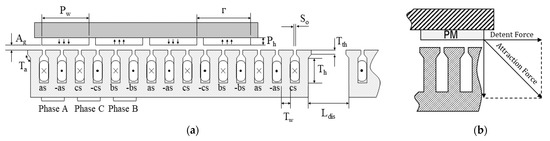
Figure 1.
Discontinuous armature arrangement PMLSM: (a) Schematic diagram of PMLSM; (b) Forces exerted in the PMLSM.
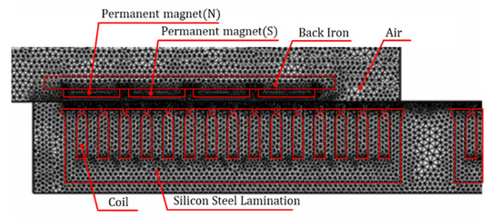
Figure 2.
2D finite elements analysis model.

Table 1.
Specifications of the discontinuous armature arrangement PMLSM.
2.2. Analytical Analysis of Detent Force
The interval distance Ldis between armatures must satisfy the following equation [20].
Or
where, Lu is the length of one stator segment and τ is the pole pitch. The electrical degree between the two stators in Equation (1) becomes 2/3π and in Equation (2) becomes 4/3π. Accordingly, if the stators are separated by Ldis, the same winding connection as the existing continuous stator can be applied to the discontinuous stator PMLSM. The end effect force of PMLSM is a major component of detent force. The discontinuous armature arrangement PMLSM has more end edges, so the end effect has a greater impact. In the case of the ideal slotless PMLSM, the detent force formula can be expressed as Equation (3) because energy variation occurs [21].
where Ava is the Fourier coefficient of magnetization vector harmonic component, Gμa is the relative permeability in the gap, μ is the harmonic order k = π/τ, and Lef is the length of the lamination stack that provides rigidity to the stator. Using Equations (1) and (2), the detent force can be expressed as Equation (4).
As shown in Equation (4), when μ is (3 m), the 3 m order harmonic components are amplified three times as Fdet (x) = 3Fden (x).
2.3. Characteristics of Investigated Model
If the armature is aligned when the mover is in operation, a slot effect occurs. When the mover enters the end edge, it is subjected to a force owing to the end effect. Figure 2 illustrates the detent force and harmonic component generated with the movement of the mover.
As shown in Figure 3a, when the mover is aligned with the armature, a slot effect of ±0.96 N is generated; moreover, as the movers enters the end of the armature, an end effect of ±9.33 N is generated. The detent force due to the ends is approximately 9.7 times larger than that when the armature is aligned. Because the period of the end force is г, the multiple components of the 2nd-order harmonic component are primarily generated by the end effect. As indicated by Equation (4), the multiple components of the 3rd-order harmonic component are amplified by a factor of three, and the other harmonic components are suppressed. As shown in Figure 3b, the 6th-order harmonic component is demonstrated to be significantly larger, owing to the amplification of the 2nd-order and 3rd-order harmonic components.
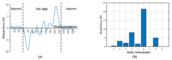
Figure 3.
FEM result of detent force at no load: (a) Detent force caused by end effect; (b) Harmonic components of detent force.
Figure 4 presents the analysis results for the back EMF and harmonics when the speed of the mover was 0.2 m/s. The THD value was 2.03%. The field distribution and flux density contours of the stator teeth are presented in Figure 5. The maximum magnetic flux density generated in the circuit was 1.32 T, confirming that the circuit was properly designed.
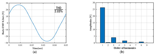
Figure 4.
No-load voltage back EMF: (a) Back EMF of initial model; (b) Harmonic components of back EMF.
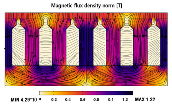
Figure 5.
Field distribution and flux density contours of the circuit.
3. Multipurpose Optimal Design of PMLSM Using the Design of Experiments
3.1. Screening
The primary parameters that affected each objective function were selected to minimize the detent force and the THD of the back EMF due to the slot effect and to prevent the saturation of the circuit. Through screening, the parameters with insignificant main effects were pooled. The fractional factorial design method was adopted to identify the main effect, and a small number of interaction effects with a small number of simulations and 7 shape parameters were screened to identify 7 main effects and 14 two-factor interaction effects. Figure 6 presents an overview of the optimization process. The constraints of the shape parameters are presented in Table 2.
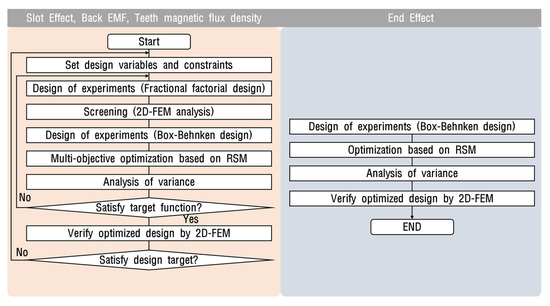
Figure 6.
Optimization process flow chart.
Table 2.
Design variables and boundary of the stator and the mover.
Constraints on the shape of permanent magnets and armature were set in consideration of the distance between the mover and the stator, the distance between the stators, the ratio between the slot and the pole, and the winding area. In this study, 33 simulation runs were performed using fractional factorial design. The simulation conditions and results for each shape parameter are presented in Table 3.
Table 3.
Fractional factorial design and results.
The parameters not significant to the detent force or the THD of the back EMF due to the slot effect, as well as the magnetic flux density of the tooth, i.e., the objective functions, to the error terms were pooled. Subsequently, a Pareto chart was plotted, as shown in Figure 7. The main effect based on an analysis of variance (ANOVA) is illustrated in Figure 8.
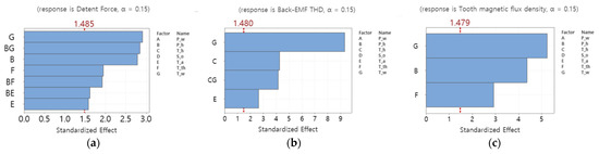
Figure 7.
Pareto chart of the standardized effects: (a) Detent force; (b) Back EMF; (c) Magnetic flux density.
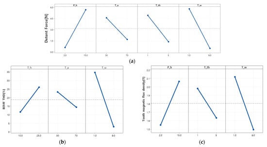
Figure 8.
Main effects plot for objective functions obtained from the fractional factorial design: (a) Detent force; (b) Back EMF; (c) Magnetic flux density.
The tooth width, tooth height, tooth tip height, and tooth tip angle exhibited significance with respect to the detent force, and interactions existed between the permanent magnet height, and the tooth width, tooth tip height, and tooth tip angle. For the THD of the back EMF, the tooth width, tooth height, and tooth tip angle exhibited significance, and an interaction existed between the tooth height and tooth width. For the magnetic flux density of the tooth, the tooth width, permanent magnet height, and tooth tip height exhibited significance. Hence, the five control parameters that affected each objective function were selected, as shown in Figure 9.
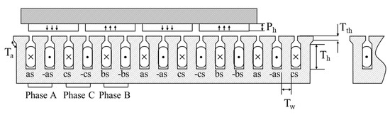
Figure 9.
Design variables for optimization.
3.2. Multi Objective Optimization Based RSM
In design optimization, thousands of iterative computations may be required before convergence to the optimal value. If a numerical analysis is performed for every process, the computation time is long. Therefore, design optimization, by constructing an approximation model between the design parameters and the objective functions, would be an efficient approach. In this study, the experiment was designed using the Box–Behnken design (BBD) method for optimization. Table 4 presents the obtained simulation results based on the five parameters (permanent magnet height, tooth height, tooth tip angle, tooth tip height, and tooth width) described in Section 3.1.
Table 4.
Box–Behnken design and results for each process.
ANOVA was performed using the data presented in Table 4, and the results are presented in Table 5, Table 6 and Table 7. After the simulation, the results for each level were analyzed using Minitab. The coefficient of determination (R2) can be defined as the ratio of the explained amount of variation to the total valuation. It is a measure of the goodness-of-fit of the model equation. For an R2 value closer to 100%, the experimental model equation is closer to the real values. The R2 values of the objective functions based on the shape parameters (excluding the non-significant terms) were 66.67% for the detent force, 97.40% for the back EMF THD, and 97.08% for the tooth magnetic flux density, validating the significance within 5% of the significance level. These results indicate that the regression model properly explains the relationship between the performance parameters and the design variables. A regression analysis was performed to predict the objective functions according to the level change of the five control parameters, and the result obtained from calculating the value of the equation for the quadratic polynomial regression curve is presented as follows:
Table 5.
Analysis of variance of the detent force.
Table 6.
Analysis of variance of the back-EMF THD.
Table 7.
Analysis of variance of the magnetic flux density.
Figure 10 shows the effect of each design variable. For detent force, tooth width and tooth tip height and tooth width had an effect, and tooth tip height had an effect in the form of a quadratic function. For back-EMF THD, all design variables except tooth tip height were affected among the five variables, and tooth width was affected in the form of a quadratic function. For magnetic flux density, permanent magnet height, tooth height, and tooth width were affected, and permanent magnet height and tooth width were affected in the form of quadratic functions. Figure 11 shows the response surface for terms with interactions. As shown in Figure 11a, the detent force decreased as the tooth tip height was lower and the tooth width was wider. In addition, the detent force was decreased even when the tooth tip height was high and the tooth width was narrow. As shown in Figure 11b, both tooth width and permanent magnet height showed a curvature effect on magnetic flux density. As shown in Figure 11c, the back-EMF THD decreased as the tooth height decreased and the tooth tip angle increased, and showed a curvature effect on the tooth width.
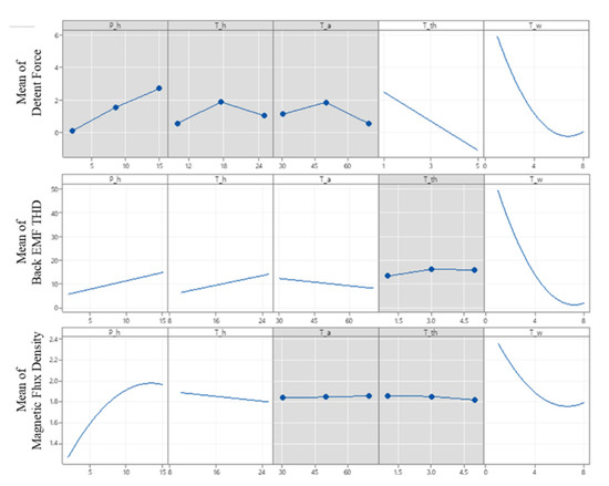
Figure 10.
Main effect plot.
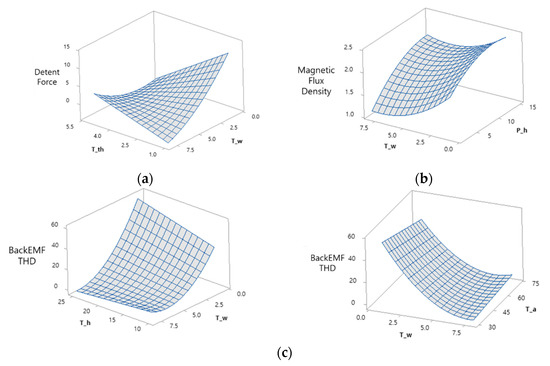
Figure 11.
Response surface of an interaction term. (a) Detent force (b) Magnetic flux density (c) Back EMF THD.
For the optimization of each objective function, a multi-objective optimization-based RSM was adopted. As shown in Table 8, the objective functions were optimized by varying the target values for each case.
Table 8.
Control factors and targets for each cases.
In Case 1, if the value of the magnetic flux density is minimized, the detent force and THD value of the back EMF exceed the values in the initial model. Therefore, Case 2, in which the magnetic flux density is limited between 1.0 and 1.5 T, is selected as the optimal value. For this case, the derived results were as follows: the height of the permanent magnet was 3.3 mm; the height of the tooth was 25 mm; the tooth tip angle and tooth tip height had minimum values of 30° and 1 mm, respectively; and the tooth width was 6.1 mm. Figure 12 illustrates the detent force relative to the slot effect of the optimized shape.
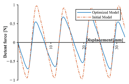
Figure 12.
Detent force by slot effect of initial model and optimized model.
For the optimized model, a detent force of 0.62 N was generated, which was reduced by approximately 35% compared with the initial model. As shown in Figure 13a, the maximum value of the back EMF of the optimized shape increased from 27.3 V (initial model) to 30.89 V. Although the height of the permanent magnet decreased, it was considered that the back EMF increased according to the change in the air gap. In the optimized model, as shown in Figure 13b, the 3rd-order back EMF harmonic component decreased. The THD decreased by 0.57%. As shown in Figure 14, the maximum magnetic flux density generated in the optimized circuit was 1.18 T, indicating that the circuit was adequately designed.
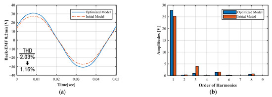
Figure 13.
No-load voltage back EMF: (a) Back EMF of initial model; (b) Harmonic components of back EMF.
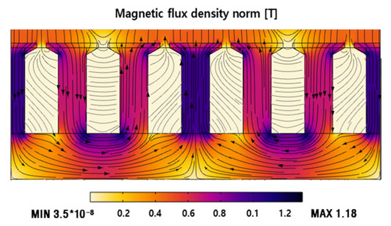
Figure 14.
Field distribution and flux density contours of Optimized Circuit.
4. Optimal Design of the End Edge Auxiliary Teeth
4.1. Setting of Design Parameter
A significant change in the air gap generated at the end edge induces a greater detent force than when the mover is aligned with the armature. Therefore, auxiliary teeth in a trapezoidal shape, which can induce a gradual change in the air gap at the end edge of the armature, were installed, and each shape parameter was optimized. Figure 15 illustrates the shape of these auxiliary teeth.
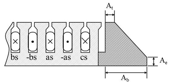
Figure 15.
End edge auxiliary teeth.
The auxiliary teeth were installed as far apart as the width of the armature and slot. Additionally, the length of the top of the tooth (At), the length of the tooth in the moving direction of the mover (Ab), and the height of the bottom of the tooth (Ae) were selected as the main shape parameters. The auxiliary teeth were composed of laminated silicon steel, similar to the armature core. The range of the shape parameters was set as 0–30 mm, considering the tooth height and armature spacing.
4.2. Auxiliary Teeth Shape Optimization Using RSM
For design optimization using the approximate model, 15 simulation runs were conducted using the BBD method. The results are presented in Table 9. The impact of each shape parameter obtained from Table 9 is illustrated in Figure 16. As shown, At significantly impacts the detent force, and there is an interaction between this parameter and the detent force. Ae also affects the detent force, while Ab in the direction of movement has a negligible impact on the detent force. Therefore, Ab was fixed at the maximum value of 30 mm.
Table 9.
Design variables and boundary of the auxiliary teeth.
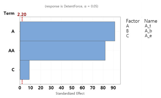
Figure 16.
Pareto chart for end effect detent force.
Figure 17 shows the response surface for each design variable affecting the detent force. At is in the form of a quadratic curve; in the range of At = 10–15 mm, the detent force due to the end effect is minimized when Ae is minimized.
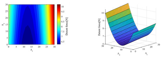
Figure 17.
Response surface of At (mm) vs. Ae (mm), Detent force (N).
Table 10 shows the ANOVA results for each shape parameter affecting the objective functions. The R2 value, i.e., the coefficient of determination of the objective function according to the shape parameters, excluding the non-significant terms, was 99.87%, confirming that the results were within 5% of the significance level. It can be deduced that the regression model adequately explains the relationship between the performance parameters and the design variables. The results obtained from calculating the values of the equation for the quadratic polynomial regression curve are as follows:
Table 10.
Analysis of variance of end edge detent force.
As indicated by the response optimization graph presented in Figure 18, when At was 12.42 mm and Ae was at the minimum value, a detent force of 6.23 N was generated.
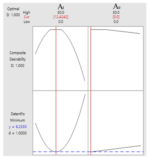
Figure 18.
Optimization of detent force using response surface methodology.
Figure 19a shows the detent force of the PMLSM with the installation of the optimized auxiliary teeth. In the absence of the auxiliary teeth, a detent force of ±9.33 N was generated when the mover entered or exited the armature; however, with the installation of the auxiliary teeth, a detent force of ±6.49 N, with a 30.44% reduction, was generated. Figure 19b shows a comparison between the harmonic components of the initial and optimized models. As shown, all the components except for the 1st- and 5th-order harmonic components decreased; additionally, the 6th-order component (with the largest value) significantly decreased.
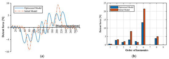
Figure 19.
FEM results of end effect detent force at no load (a) Detent force of optimized model; (b) Detent force harmonic components of optimized model.
4.3. Analysis of Optimized Results
Table 11 shows the initial value and the optimized estimate result for each objective function, as well as the FEA result values obtained, using the optimized shape parameters.
Table 11.
Optimized results.
For slot effect and end effect, there were differences of 19.4% and 4.0% in the estimate and FEA results, respectively. For back EMF THD and magnetic flux density, there were differences of 0.3% and 10.2%, respectively. Shape optimization reduced slot effect by 55%, end effect by 44%, and back-EMF THD by 0.57%. In the case of the slot effect, the R2 (pred) value, indicating the predicted response of the regression equation, was relatively small (50.06%); however, a comparison with the FEA results confirmed that the regression model exhibited optimal prediction performance for the simulation result.
5. Conclusions
Shape optimization of the armature core was performed to reduce the detent force and back EMF harmonic components that act as thrust ripple in a PMLSM system with a discontinuous armature arrangement, degrading the operating performance of the system and preventing tooth saturation. Additionally, auxiliary teeth in a trapezoidal shape were installed to reduce the detent force generated at the ends of the armature, and an optimal shape was determined for minimizing the detent force. First, seven dimensions for the shape of the armature core were set as design parameters, and the boundary was determined. Next, five major shape parameters were derived using the fractional factorial design method. The derived main shape parameters were optimized through the multi-objective optimization based on the RSM. Through the optimization, the detent force and THD of the back EMF were decreased. The maximum value of the magnetic flux density generated by the armature core was 1.18 T, which was within the appropriate range. Subsequently, auxiliary teeth were installed to reduce the detent force generated at the end edge, and the shape was optimized. The BBD method was used to derive two shape parameters affecting the detent force among the three shape parameters; additionally, a response surface was constructed. When the optimized auxiliary teeth were installed, the end edge detent force was reduced by approximately 30% compared with the case without the auxiliary teeth. Based on the results obtained in this study, it is expected that the operation performance can be improved in the discontinuous armature arrangement PMLSM.
Author Contributions
J.-H.K., J.-K.K. and E.-S.J. conceived and designed the simulations; J.-H.K. performed the simulations and experiments; J.-H.K. and J.-K.K. analyzed the data; J.-H.K., J.-K.K. and E.-S.J. contributed analysis tools; J.-H.K., J.-K.K. and E.-S.J. wrote the paper. All authors have read and agreed to the published version of the manuscript.
Funding
This research was supported by the Human Resource Training Program (S2755803) for business-related research and development of Ministry of SMEs and Startups in 2019.
Institutional Review Board Statement
Not applicable.
Informed Consent Statement
Not applicable.
Data Availability Statement
Not applicable.
Conflicts of Interest
The authors declare no conflict of interest.
References
- Aoyama, Y.; Hasegawa, Y.U.; Sasaki, M.; Nakatsugawa, J.; Iwaji, Y.; Komura, A. Development of high-acceleration ltainear motor to realize resource saving and high productivity. Electr. Eng. Jpn. 2018, 202, 55–63. [Google Scholar] [CrossRef]
- Boldea, I.; Tutelea, L.N.; Xu, W.; Pucci, M. Linear electric machines, drives, and MAGLEVs: An overview. IEEE Trans. Ind. Electron. 2018, 65, 7504–7515. [Google Scholar] [CrossRef]
- Seki, K.; Watada, M.; Torii, S.; Ebihara, D. Discontinuous arrangement of long stator linear synchronous motor for transportation system. In Proceedings of the Second International Conference on Power Electronics and Drive Systems, Singapore, 26–29 May 1997; Volume 2, pp. 697–702. [Google Scholar]
- Kim, Y.-J.; Watada, M.; Dohmeki, H. Reduction of the cogging force at the outlet edge of a stationary discontinuous primary linear synchronous motor. IEEE Trans. Magn. 2007, 43, 40–45. [Google Scholar] [CrossRef]
- Jung, I.-S.; Yoon, S.-B.; Shim, J.-H.; Hyun, D.-S. Analysis of forces in a short primary type and a short secondary type permanent magnet linear synchronous motor. IEEE Trans. Energy Convers. 1999, 14, 1265–1270. [Google Scholar] [CrossRef]
- Jia, H.; Cheng, M.; Hua, W.; Zhao, W.; Li, W. Torque ripple suppression in flux-switching pm motor by harmonic current injection based on voltage space-vector modulation. IEEE Trans. Magn. 2010, 46, 1527–1530. [Google Scholar] [CrossRef]
- Zhu, Y.-W.; Jin, S.-M.; Chung, K.-S.; Cho, Y.-H. Control-based reduction of detent force for permanent magnet linear synchronous motor. IEEE Trans. Magn. 2009, 45, 2827–2830. [Google Scholar] [CrossRef]
- Abbaszadeh, K.; Rezaee Alam, F.; Saied, S.A. Cogging torque optimization in surface-mounted permanent-magnet motors by using design of experiment. Energy Convers. Manag. 2011, 52, 3075–3082. [Google Scholar] [CrossRef]
- Kim, Y.-J.; Hwang, S.-S.; Jeong, Y.-S. Cogging force reduction of a stationary discontinuous armature PM-LSM by magnet segmentation. IEEE Trans. Magn. 2009, 45, 2750–2753. [Google Scholar]
- Zhang, H.; Kou, B.; Jin, Y.; Zhang, H. Investigation of auxiliary poles optimal design on reduction of end effect detent force for PMLSM with typical slot–pole combinations. IEEE Trans. Magn. 2015, 51, 1–4. [Google Scholar] [PubMed] [Green Version]
- Zhu, Y.-W.; Lee, S.-G.; Chung, K.-S.; Cho, Y.-H. Investigation of auxiliary poles design criteria on reduction of end effect of detent force for PMLSM. IEEE Trans. Magn. 2009, 45, 2863–2866. [Google Scholar] [CrossRef]
- Seo, S.-W.; Jang, G.-H.; Koo, M.-M.; Choi, J.-Y. Characteristic analysis of the influence of auxiliary teeth and notching on the reduction of the detent force of a permanent magnet linear synchronous machine. IEEE Trans. Appl. Supercond. 2018, 28, 1–5. [Google Scholar] [CrossRef]
- Chung, S.-U.; Kim, J.-W.; Woo, B.-C.; Hong, D.-K.; Lee, J.-Y.; Koo, D.-H. Force ripple and magnetic unbalance reduction design for doubly salient permanent magnet linear synchronous motor. IEEE Trans. Magn. 2011, 47, 4207–4210. [Google Scholar] [CrossRef]
- Huang, X.; Qian, Z.; Tan, Q.; Li, J.; Zhou, B. Suppressing the thrust ripple of the permanent magnet linear synchronous motors with different pole structures by setting the modular primary structures differently. IEEE Trans. Energy Convers. 2018, 33, 1815–1824. [Google Scholar] [CrossRef]
- Chung, S.-U.; Kim, J.-W.; Woo, B.-C.; Hong, D.-K.; Lee, J.-Y.; Chun, Y.-D.; Koo, D.-H. Design and experimental validation of doubly salient permanent magnet linear synchronous motor for precision position control. Mechatronics 2013, 23, 172–181. [Google Scholar] [CrossRef]
- Islam, M.S.; Mir, S.; Sebastian, T.; Underwood, S. Design considerations of sinusoidally excited permanent-magnet machines for low-torque-ripple applications. IEEE Trans. Ind. Appl. 2005, 41, 955–962. [Google Scholar] [CrossRef]
- Hwang, K.Y.; Jo, J.H.; Kwon, B.I. A study on optimal pole design of spoke-type IPMSM with concentrated winding for reducing the torque ripple by experiment design method. IEEE Trans. Magn. 2009, 45, 4712–4715. [Google Scholar] [CrossRef]
- Zhu, Z.Q.; Chen, J.T.; Wu, L.J.; Howe, D. Influence of stator asymmetry on cogging torque of permanent magnet brushless machines. IEEE Trans. Magn. 2008, 44, 3851–3854. [Google Scholar] [CrossRef]
- Myers, R.H.; Montgomery, D.C.; Anderson-Cook, C.M. Response Surface Methodology: Process and Product Optimization Using Designed Experiments; John Wiley & Sons: Hoboken, NJ, USA, 2016; ISBN 9781118916032. [Google Scholar]
- Zhang, C.; Zhang, L.; Huang, X.; Yang, J.; Shen, L. Research on the method of suppressing the end detent force of permanent magnet linear synchronous motor based on stepped double auxiliary pole. IEEE Access 2020, 8, 112539–112552. [Google Scholar] [CrossRef]
- Huang, L.; Chen, Y.; Kong, H.; Lu, Q.; Ye, Y. Analysis of a permanent magnet linear synchronous motor with segmented armature for transportation system. In Proceedings of the 2014 17th International Conference on Electrical Machines and Systems (ICEMS), Hangzhou, China, 22–25 October 2014; pp. 1791–1796. [Google Scholar]
Publisher’s Note: MDPI stays neutral with regard to jurisdictional claims in published maps and institutional affiliations. |
© 2021 by the authors. Licensee MDPI, Basel, Switzerland. This article is an open access article distributed under the terms and conditions of the Creative Commons Attribution (CC BY) license (https://creativecommons.org/licenses/by/4.0/).