Featured Application
Potential application of the work is in power generation plants.
Abstract
Dissimilar metal joining has always been a challenging task because of the metallurgical incompatibility and difference in melting points of alloys being joined. Diffusion and mixing of alloying elements from dissimilar base metals at the weld often cause unwanted metallurgical changes resulting in unsuccessful welds or underperformance of the weldment. Solid-state dissimilar friction welds of Inconel 718 and F22 were prepared in this study with an Inconel 625 interlayer to address the carbon enrichment of Inconel 718 during the welding. Defect-free rotary friction welds were produced in this study. Microstructural and mechanical properties investigation of the weldments and base metals was carried out, and results were analysed. Intermixing zone was observed at the weld interface due to the softening of the metal at the interface and rotatory motion during the welding. The high temperatures and the plastic deformation of the intermixing zone and thermo-mechanically affected zone (TMAZ) resulted in the grain refinement of the weld region. The highest hardness was observed at the Inconel 718/F22 weld interface due to the plastic strain and the carbon diffusion. The tensile specimens failed in the F22 base metal for the weld prepared with and without the Inconel 625 interlayer. Inconel 718/F22 welds exhibited lower toughness values compared to the Inconel 718/F22 welds prepared with Inconel 625 interlayer.
1. Introduction
Carbon and low-alloy steels in quenched and tempered conditions contain finely dispersed cementite in the microstructure. This dispersed cementite tends to form micro galvanic cells and has been reported to cause severe corrosion in water containing hydrocarbon fluids and dissolved CO2 during oil and gas production [1]. To minimise the CO2 attack of components used in oil and gas production, researchers have employed steels that form adherent high-quality chromia film with the addition of 1–5 wt% Cr. Alloy F22 is one such grade with 2–2.5 wt% Cr and a small amount of Mo (≈1%), which shows moderate corrosion resistance in aqueous environments. However, under mild to severe corrosive and high-temperature conditions, nickel-based superalloys are the materials for structural designers. Inconel 718 is a widely used Ni-based alloy in various applications ranging from structural components in power generation plants to highly specialised blades in jet engines [2]. Having properties such as superplastic behaviour, ease of machinability, and weldability, although not as attractive as some other alloys, Inconel 718 displays high strength properties at unusually high temperatures (about 650 °C) [3]. Apart from a good strength and corrosion resistance, Inconel 718 also displays excellent toughness at cryogenic temperatures and hydrogen embrittlement resistance. These facts push Inconel 718 high up in the desirability index of most designers of very special high-end applications. Inconel 718 derives its high strength property from the age-hardening phenomenon [2]. In Inconel 718, the matrix is a solid solution of Ni and Fe. An optimum percentage of intermetallic and carbide precipitates distributed in the matrix gives the alloy outstanding properties [4]. Most important of all the precipitates are γ′ (Ni3(Al, Ti, Nb)) and γ″ (Ni3Nb). These precipitates remain coherent with the matrix, even at high temperatures, retarding the dislocation movement and thus rendering the strength properties to the alloy.
Often it is required that Inconel 718 has to be joined with other materials, making it the so-called dissimilar weld. Henderson et al. suggested that Inconel 718 to stainless steel joints find applications in power generation plants [5]. Ferriti et al. reported a need to obtain strong and clean joints between Inconel 718 and stainless steel to construct certain sections of the internal space station [6]. Mortezaie and Shamanian have reported that the Inconel 718 and 310S dissimilar joints find applications in land-based gas turbines [7]. Notwithstanding the enormous advantages that these dissimilar welds joints can offer, often it is inherently a challenge to join dissimilar materials. This is truer when the materials in question are on the opposite ends of a spectrum concerning physical and metallurgical properties. For instance, a highly conductive material is harder to join with a less conductive material. Similarly, while joining alloys with a wide difference in melting temperatures, it becomes difficult to manage the melting and solidification behaviour of the alloys. Even after assuming that the above problems could be managed by manipulating the weld setup, the metallurgical incompatibility plays the role of a spoilsport. An alloy that does not dissolve into each other in a solid state would often form hard intermetallic compounds that render the whole joint brittle. In this regard, a transition joint solves many of the problems faced in the direct welding of dissimilar alloys. A transition joint is one that has an interlayer made of the third alloy, and this layer mitigates the problems such as mismatch in physical properties, but most importantly, mismatch in metallurgical solubility [8,9,10]. By identifying a suitable interlayer, we may find that the harmful intermetallic phases could be significantly reduced.
Jijun et al. welded stainless steel to copper using Ni as an interlayer [11]. Porosity and liquation cracking problems present in the direct joints disappeared with the use of Ni interlayer. Ni also proved helpful while joining the stainless steel to a high melting point metal, namely, molybdenum [12]. Some authors have used even multiple interlayers to stop the inter-diffusion of highly incompatible base materials into each other. Hu et al. used a Cu/Ta multi-interlayer to weld highly incompatible Inconel 718 and Ti-6Al-4V joint combination [13]. Similarly, Xue-long Cao et al. positioned Ni/Cu in the middle of aluminium to steel weld joints [14]. Metallurgical compatibility of the interlayer with both the base metals is a prime criterion for selecting the interlayer while preparing the dissimilar weld joints using the interlayer.
The shift to advanced ultra-supercritical (AUSC) plants for power generation is mainly because of the higher power generation efficiency and lower carbon footprint [15]. Ferritic/martensitic steels are used for the thicker sections of the boiler structure. In contrast, the use of super austenitic steels and nickel base superalloys is limited to thin sections because of the high cost of these alloys. Joining of superalloys to the high strength steels can be done by mechanical fastening for turbine engine applications [16]. However, fusion welds display superior strength and fatigue performance compared to mechanical joining, especially in applications such as power generation [16]. Re-heater tube, superheaters, and boiler header components employ dissimilar steel/superalloy joints for improved performance and economics [15]. 2.5Cr-1Mo (F22) steel is the most commonly used power plant steel, showing good strength and resistance to long-term high-temperature exposure. However, the dissimilar superalloy/high strength steel fusion weldments showed enrichment of C and Fe because of the dilution and displayed solidification-related cracking behaviour [16]. The development of dissimilar joints between Inconel 718 and F22 is advantageous technically and economically in applications such as nuclear power generation and repair welding [17]. However, the carbon content in F22 is higher compared to the minimum requirement in the Inconel 718. Carbon, being an interstitial alloying element, shows higher diffusion from the F22 to Inconel 718, compared to the other heavy elements during the joining process. It was reported that the NbC and Laves phases promote microfissuring and hot cracking in the Inconel 718 welds by forming the incipient liquid films at the intergranular regions during the weld thermal cycle and solidification, respectively [18]. The results of the spot varestraint tests revealed that there was an 18% increase in cracking susceptibility with the increase in carbon content (0.02 to 0.06 wt%) in cast Inconel 718 alloys. An interlayer that shows metallurgical compatibility with F22 and Inconel 718 can be suggested as a suitable solution for preparing Inconel718/F22 dissimilar joints. Nickel-based corrosion-resistant alloys are used as coatings on alloy steels for oil and gas industry applications. Interestingly, the Inconel 625 is commonly used for the weld overlay on high-strength alloy steels such as F22 because of its good metallurgical compatibility. Inconel 625 is a weld overlaid on F22 for subsea oil platform applications to provide corrosion resistance [19,20]. As a nickel-based superalloy, Inconel 625 is a suitable candidate material as an interlayer to join Inconel 718 to the high-strength alloy steel F22. Good weldability, high-temperature oxidation, and corrosion resistance in hostile environments make Inconel 625 a Ni-based solid solution strengthened superalloy, a popular candidate for marine, petrochemical, refinery, and aero industries [21]. High-temperature strength of this alloy is improved by adding Mo and Nb, while Cr results in resistance to oxidation and corrosion. Additional strengthening of the Inconel 625 is achieved by carbide-forming elements such as Nb, Ti, and Mo. Inconel 625 contains ≈0.08 wt% carbon content, and the ductility of the Inconel 625 is less sensitive to the increase in the carbon content from the alloy F22 during the friction welding or subsequent post-wed heat treatment. It would be interesting to investigate the effect of the Inconel 625 interlayer on the metallurgical and mechanical properties of the Inconel 718-F22 dissimilar friction weld joints. To the authors’ knowledge, no reports have been published in the literature, and such a study is needed to understand the role of interlayer during the dissimilar joint preparation in the manufacturing industry. This study reports an investigation of the microstructural and mechanical properties of the Inconel 718-F22 friction weld joints prepared using the Inconel 625 interlayer.
2. Material Description and Experimental Procedures
Base metal alloys, viz., Inconel 718, Inconel 625, and F22 cylindrical rods (20 mm φ and 100 mm length) were used in this study. The chemical composition of the base metals is shown in Table 1. Inconel 718 and Inconel 625 are in mill-annealed condition, while the F22 is quenched and tempered. Inconel 718 and Inconel 625 are in-process annealed at 1010 and 1050 °C, respectively, and subjected to rapid cooling. The heat treatment of F22 involves heating to a temperature of 1000 °C to fully dissolve carbides and quenching to room temperature. The quenched F22 steel is tempered for 2 h at 650 °C to reduce the martensite hardness and form stable carbides. The base metal rods were face-prepared by machining and acetone cleaning. Welding was carried out using a continuous drive rotary friction welding machine (ETA Technology, Bangalore, India) with a maximum axial force of 150 kN. The welding procedure corresponding to the rotary friction welding machine has been explained elsewhere [22]. Weld trials were carried out to optimise burn-off length, upset and friction pressures, and final friction welding parameters (Table 2). In order for the the welding parameters to be optimised, the friction pressure, burn-off length, and upset pressure were varied one parameter at a time. Lower friction pressures (below 200 MPa) resulted in longer weld times and poor flash appearance with flaky morphology, indicative of insufficient plasticisation. Once the friction pressure was frozen at 200 MPa, the best flash appearance was observed at 6 mm burn-off length and 400 Mpa upset pressure. Visual flash inspection, burn-off length, and weld drop tests were employed for the optimisation of the welding parameters. The Inconel 718/F22 weld joints with Inconel 625 interface were developed in two stages. F22-Inconel 625 friction welds were prepared during the first stage of the experiments. The F22/Inconel 625 friction weld joints were cut on the Inconel 625 side at 15 mm away from the weld interface. After we removed the flash and face preparation, second stage welding was performed between Inconel 718 and Inconel 625/F22 rod to produce the Inconel 718/F22 friction weld joint with Inconel 625 interlayer. The schematic of the Inconel 718/F22 friction weld joint development with Inconel 625 as an interlayer is visualised in Figure 1. For comparison, Inconel 718/F22 friction weld joints without interlayer were produced in this study.

Table 1.
Chemical composition (wt%) of the Inconel 718, Inconel 625, and F22.
Table 2.
Welding parameters.
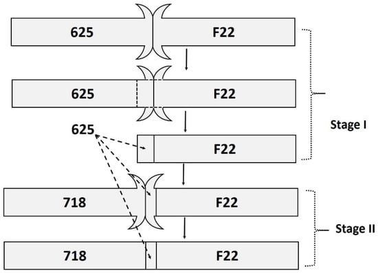
Figure 1.
Schematic diagram showing the steps during the preparation of the Inconel 718/F22 friction weld joint with Inconel 625 interlayer.
2.1. Metallographic Examination
The dissimilar rotary friction welded Inconel 718/Inconel 625/F22 transition joint in as-welded condition was suitably sectioned in the transverse direction to the weld, mounted, mechanically polished, and etched for microstructural study. Etching was carried out using Kalling’s reagent (5 gm CuCl2, 100 mL HCl, 100 mL ethanol) for Inconel 718 and Inconel 625, whereas 2% Nital (2 mL HNO3, 98 mL methanol) was used for F22. The etched sample was examined under the Leitz optical microscope and Nikon SMZ745T stereomicroscope (Nikon Instruments Inc., New York, NY, USA) for microstructural and microstructural features. The welded specimen was examined under a scanning electron microscope (SEM) using VEGA 3LMV TESCAN, and microchemical analysis of the welds across the weld interface was carried out using Oxford Instrument energy-dispersive X-ray (EDS) spectrometer (TESCAN ORSAY HOLDING, Brno, Czech Republic). The line intercept method was employed for the determination of the average grain size of the base metal and thermo-mechanically affected zone (TMAZ). X-ray diffraction (PANalytical, Malvern, United Kingdom, X’pert powder XRD) technique using Cu-Kα radiation was used for the phase analysis of the base metals.
2.2. Mechanical Testing
Vickers microhardness tester (MMT-X Matsuzawa, Akita Prefecture, Kawabetoshima, Japan) was employed to investigate the microhardness variation across the weld region at 500 g load for 15 s using a diamond pyramid indenter. An optimum interval of 0.5 mm between each measurement was also maintained. The tensile properties of all the base metals and the weld were evaluated according to ASTM E8 standard using a Universal Testing Machine (Jinan WDW-100S, Jinan, China). A constant crosshead speed of 0.5 mm/min was maintained for all the tests. Room temperature Charpy V notch impacts test of base metals and welds was carried out following the ASTM E-23 standard. Samples were etched before notch preparation to ensure the notch placement at the interface of the friction weld joint for the impact toughness investigation of the weld joint. The average of the results of the three samples each for the tensile and impact investigation of the weldments was reported in this study.
3. Results and Discussion
3.1. Microstructure: Base Metal
Figure 2a,b shows optical and scanning electron micrographs of the alloy F22, respectively. Optical micrograph of the F22 showed tempered martensitic microstructure without the apparent grain boundaries and phase morphology due to the fine nature of the temperate martensite. However, the higher magnification SEM micrograph of the F22 (Figure 2b) clearly showed tempered martensite colonies outlined by the prior austenitic grain boundaries. Inconel 718 and Inconel 625 base metal optical and SEM micrographs showed a grain structure, respectively, as seen in in Figure 2c–f. The average grain size values of the Inconel 718 and Inconel 625 were 23 ± 2 µm and 85 ± 3 µm, respectively. Twins were observed in the microstructure of the Inconel 625. X-ray diffraction patterns of base metals were indexed and are shown in Figure 3. Alloy F22 base metal showed diffraction peaks corresponding to the martensite, while 718 and 625 showed diffraction peaks corresponding to the austenitic phase.
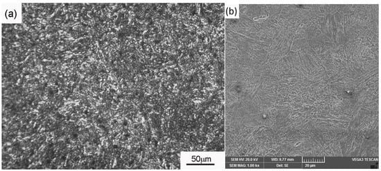
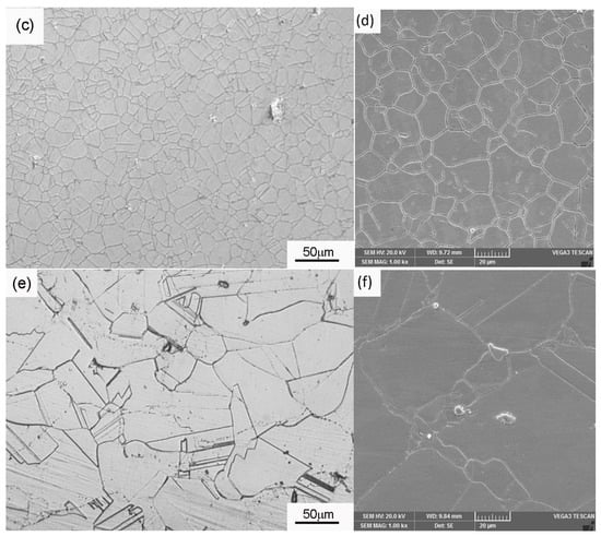
Figure 2.
Optical micrograph and secondary electron micrographs of the F22 base metal (a,b), 718 base metal (c,d), and 625 base metal (e,f).
Figure 3.
XRD diffraction patterns of the alloy F22, 718, and 625 base metals.
EDS analysis of the precipitates observed in the Inconel 718 electron micrographs were found to be rich in Ti and C, with a relatively smaller quantity of Nb (Figure 4a). These precipitates were identified as the MC type of carbides rich in Ti (M=Ti, Nb), which precipitate during cooling from higher temperatures. These MC types precipitate control grain growth during the ageing treatment and during the high-temperature service, imparting higher creep resistance to the Inconel 718 [23]. Similar MC types of carbides rich in Nb were observed from the EDS analysis of the Inconel 625 (Figure 4b). Mo and Cr were found to distribute in the γ phase because of the good solid solubility in Ni. It was reported that the preferential partitioning of the Mo and Cr into γ phase would promote carbide formation by reducing the solubility of strong carbide forming elements such as Nb and Ti [21]. Further, Mo and Cr also reduced the stacking fault energy of the γ phase and contributed to the strength by retarding the cross slip during the plastic deformation.
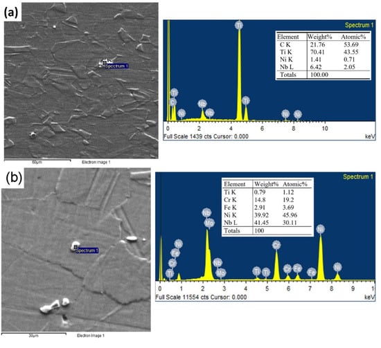
Figure 4.
Scanning electron micrograph and EDS analysis of the precipitates present in (a) Inconel 718 and (b) 625 base metals.
3.2. Microstructure: Welds
The macrograph of the weld cross-sections with and without Inconel 625 interlayer are shown in Figure 5a,b, respectively. Weld cross-section showed good metallurgical bonding at both F22-625 and 625–718 interfaces. Sound weld joint was obtained without any delamination areas and other weld defects. The presence of excellent flash at 625–718 interface indicated sufficient plasticisation of the interface materials during the welding. The Inconel718/F22 joins prepared without interlayer in Figure 5b show a bigger flash on the F22 side than the Inconel 718. Inconel 718 retains strength at higher temperatures compared to the F22, resulting in higher plasticised material on the F22. Optical micrographs of the 718-625 and 625-F22 interfaces showed deformed grain structure and intermixing zones, as shown in Figure 5c,d, respectively. The heat generated during the welding caused the plasticisation of the interface metals and resulted in the mechanical intermixing due to the rotational motion of the sample rods under the influence of the frictional and upsetting forces.
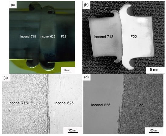
Figure 5.
The macrograph of the F22-718 friction weld joint (a) with 625 interlayer, (b) without 625 interlayer, optical micro graph of (c) 718/625 weld interface, and (d) 625/F22 weld interface.
Line scan data were obtained to investigate the mechanical intermixing and compositional variation across the weld interfaces. The EDS line scan data analysis of the Inconel 718/Inconel 625 and Inconel 625/F22 interfaces are shown in Figure 6a,b, respectively. It can be seen that the intermixing zone width was of the order of 30 µm for the Inconel 625/F22 interface, while the intermixing zone was relatively smaller at the Inconel 718/Inconel 625 interface. The Inconel 718 yielded at relatively higher stress values compared to the Inconel 625 and F22. Thus, Inconel 625 and F22 base metals experienced relatively higher deformation during friction welding. Under the influence of the rotational motion, the softened metal at higher temperatures underwent intermixing at the weld interface. SEM micrographs clearly showed the intermixed lamellae of the Inconel 625 and F22 (Figure 6b). As a result of the softening and squeezing of the material at higher rotational speed during the friction welding, parallel banded layers (viz., intermixing zone) of Inconel 625 and F22 formed at the weld interface. During the etching process, which revealed the microstructure, the F22 in the intermixing zone reacted aggressively with the etchant, relative to the 625. Hence, the regions of F22 in the intermixing zone were observed as dark lines parallel to the weld interface. Higher burn-off lengths were observed at the Inconel 625/F22 interface (7 mm) compared to the Inconel 718/Inconel 625 interface (5 mm) during the friction welding. Similar formation of the intermixing layers was reported during the dissimilar joining of the SAE1045 to 316L using the friction welding technique [24].
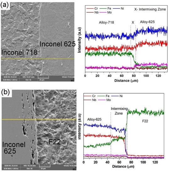
Figure 6.
SEM micrograph of weldment at (a) 718/625 interface (5 mm burn-off) with EDS line scan and (b) 625/F22 (7 mm burn-off) interface with EDS line scan.
3.3. Mechanical Properties
The hardness line profiles taken across the weld interface for the Inconel 718/F22 dissimilar friction welded joints with and without the Inconel 625 interlayer are shown in Figure 7. The TMAZ on both sides of the weld interface of the Inconel 718/F22 friction weld joints displayed a decrease in hardness value compared to the corresponding base metals. However, a sharp increase in hardness at the weld interface was observed. It can be expected that the carbide phases from the F22 dissolved at high temperatures during the welding in the intermixing zone and HAZ. The dissolved carbon from the F22 layers in contact with the Inconel 718 layers tended to react with the strong carbide formers in the Inconel 718 and form carbides [16]. The carbide phases in F22 dissolved at temperatures above 1000 °C, and the carbon entered into the solution during the welding. Because of the higher solute diffusion in the austenite phase at higher temperatures, carbon in F22 diffused towards Inconel 718 across the weld interface. Inconel 718 contains higher Cr content compared to the F22, along with strong carbide formers such as Nb and Ti. These alloying elements in Inconel 718 resulted in lower carbon chemical potential and caused the carbon from F22 to diffuse towards Inconel 718 at the weld interface. Strain hardening of the intermixing zone and carbon enrichment of the Inconel 718 layers resulted in higher hardness values in the intermixing zone of the Inconel 718/F22 friction weld joints. The F22 side of the TMAZ showed lower hardness compared to the F22 base metal for the Inconel 718/F22 friction welded joints, as can be seen from the hardness profiles. F22 softened at a relatively lower temperature than the Inconel 718 and thus experienced excessive plastic deformation of a wider zone. It was observed that the decrease in hardness in the TMAZ of the F22 was more significant in the region close to the weld interface. The higher strain energy and the higher peak temperatures experienced by the TMAZ regions of F22 close to the weld interface experienced recrystallisation followed by grain growth. It can be seen that the TMAZ of the Inconel 718 showed lower hardness and was much narrower compared to the TMAZ of the F22. Inconel 718 is a high-temperature alloy and experiences lower amount deformation compared to the F22 during the friction welding, resulting in a narrower TMAZ than the F22. This can be correlated with the formation of the relatively smaller flash of the Inconel 718 compared to the F22 flash in the Inconel 718/F22 friction weld joint (Figure 5b). Similarly, Lalam et al. reported a substantially higher flash on the EN24 side during the dissimilar friction welding of the Inconel 718 to the EN24 [16]. A decrease in the hardness of TMAZ of the Inconel 718 and F22 compared to the corresponding base metals was observed in the Inconel 718/F22 friction welded joints prepared using the Inconel 625 interlayer. However, no spikes in the hardness values were observed in the dissimilar joints prepared using the Inconel 625 interlayer.
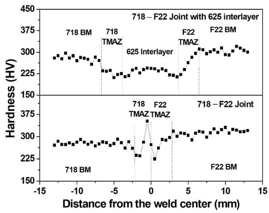
Figure 7.
The hardness distribution across the weld interface of the 718-F22 friction weld joint with and without 625 interlayer.
Inconel 718/F22 friction welded joints with and without the Inconel 625 interlayer failed in the base metal of the F22 during the tensile testing (Figure 8). The typical tensile plots of the Inconel 718/F22 friction welded joints with and without the Inconel 625 interlayer are shown in Figure 9. The tensile test results of the base metals and the welded joints, viz., yield strength (YS), ultimate tensile strength (UTS), and percentage elongation (%El) values are tabulated in Table 3. The YS and UTS of the welded joints were comparable to the F22 base metal and lower than the Inconel 718 base metal. It is worth noting that the Inconel 718/F22 friction welded joints showed lower ductility compared to that Inconel 718/F22 friction welded joints with Inconel 625 interlayer. Further, a narrow region that was not deformed can be observed at the interface of the Inconel 718/F22 friction welded joints without the Inconel 625 interlayer (Figure 8a). The formation of carbides and strain hardening in the intermixing zone resulted in the lower plastic deformation of the intermixing zone of the Inconel 718/F22 friction welded joints. It can be suggested that the Inconel 625 interlayer present between the alloys being joined, viz., Inconel 718 and F22, arrested the formation of the carbides and subsequent hard intermixing zone. The Inconel 718/F22 friction welded joints with the Inconel 625 interlayer displayed higher %El values (14 ± 0.2%) compared to the weld joint without the interlayer (12 ± 1.5%). This higher ductility of the weld joints prepared using the Inconel 625 interlayer could be attributed to the absence of the weld interface’s embrittlement because of the interlayer’s presence between Inconel 718 and F22. From the failed tensile samples (Figure 8) it can be seen that the tensile deformation was mainly on the F22 side of the weld joint. F22 displayed lower strength compared to the Inconel 718 and plastically deformed at lower stresses during the tensile testing.
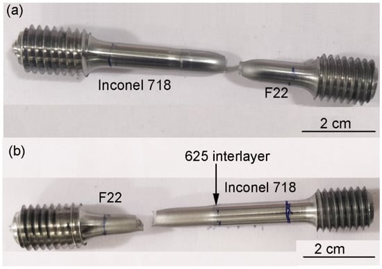
Figure 8.
Tensile failure location of the (a) 718-F22 friction weld joint and (b) 718-F22 friction weld joint with 625 interlayer.
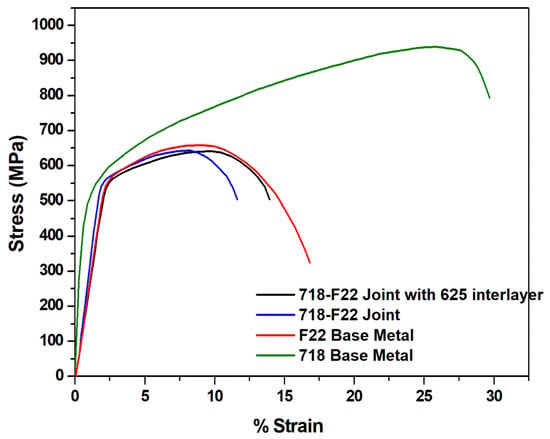
Figure 9.
Typical tensile curves of base metals and friction weld joints.
Table 3.
Results of tensile testing of base metals and 718-F22 friction weld joints with and without 625 interlayer (average properties from three tests in each case).
Charpy impact energy values of the base metals and the weld joints are shown in Table 3. F22 base metal absorbed higher energy during the impact testing compared to the other samples. The Inconel 718/F22 weld joint without the interlayer absorbed lower energy compared to the either of the corresponding base metals. This embrittlement of the Inconel 718/F22 weld joint at the weld interface can be attributed to the carbon diffusion at the intermixing zone and strain hardening. It is interesting to note that the tensile weld samples failed in the F22 base metal during the tensile testing of the weldments prepared with and without the interlayer, and hence the elongation values were close to the F22 base metal. Alloy F22 yielded at lower tensile stresses compared to the Inconel 718, and as a result, the tensile deformation was observed predominantly on the F22 side, as seen in Figure 8. However, the notch was machined at the weld interface for the Charpy impact testing of the weldments. The Inconel718/F22 weld joint absorbed the lowest energy among all the samples due to the embrittlement of the weld interface by the carbide formation. For the welds prepared using the interlayer, the notch was positioned at the Inconel 718/Inconel 625 interface for half of the samples, while the other half notch was at the Inconel 625/F22 interface. It can be seen that the Inconel 625/F22 interface displayed higher impact strength compared to the Inconel 718/Inconel 625 interface for the Inconel 718/F22 weld joints prepared using the Inconel 625 interlayer. Further, the impact strength of the Inconel 718/F22 weld joints prepared using the Inconel 625 interlayer was significantly higher compared to the dissimilar welds prepared without the interlayer. The presence of the Inconel 615 interlayer had eliminated the formation of the embrittled region at the weld interface. It improved the impact strength of the weldment when Inconel 625 interlayer was used for the weld joint preparation.
The tensile fracture surface of the base metals at weld joints is shown in Figure 10. Inconel 718 fracture surface showed fine dimpled fracture features indicative of the ductile fracture. However, the carbides present in the Inconel 718 showed brittle cleavage fracture features. F22 base metal and the welded joints showed fibrous and dimples fracture features indicative of the ductile fracture. Both the weld joints prepared in this study failed in the F22 base metal, and hence the fracture features were similar to the F22 base metal. In this study, F22 was joined with the Inconel 625 during the first stage of the joint preparation. Subsequently, F22/Inconel 625 joint was welded with Inconel 718 to produce the weldment with an interlayer. However, studies are needed with similar joints prepared by welding Inconel 718 to Inconel 625 in the first stage of experiment, which is to be welded with F22 in the second stage. This kind of change in sequence could have a significant impact on the weldment properties. Further, future studies are needed to investigate the effect of the second weld heating cycle on the microstructure of already formed first weld for the Inconel 718/F22 weld joints with Inconel 625 interlayer. In the investigation of the precipitate formation during welding, detailed high-resolution, microscopic studies would shed more light on the microstructure–property correlations.
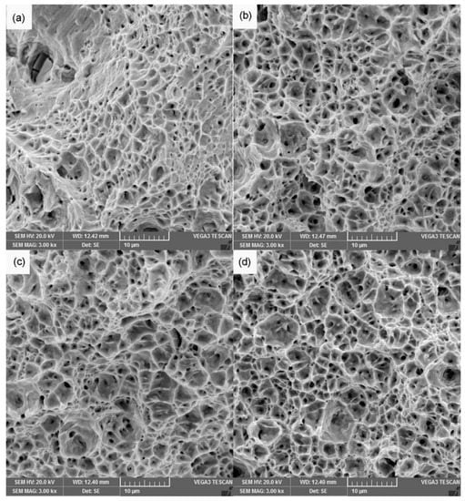
Figure 10.
Room temperature tensile fracture morphology of (a) 718 base metal, (b) F22 base metal, (c) 718-F22 joint, and (d) 718-F22 joint with 625 interlayer.
4. Conclusions
Inconel 718/F22 rotary friction welded joints with and without Inconel 625 interlayer were successfully produced in this study. Microstructural and mechanical properties investigation of the weldments was carried out and analysed. The results of the study are summarised as follows:
- Weldments were free of weld defects such as porosity or cracks, as evidenced by optical and electron microscopic investigations.
- Higher hardness was observed at the weld interface of the Inconel 718/F22 rotary friction welded joints, while welded joints with Inconel 625 interlayer did not show such a hardness jump.
- Tensile samples failed in the F22 base metal for welds prepared with and without interlayer. Inconel 718/F22 rotary friction welded joints prepared using Inconel 625 interlayer showed higher ductility compared to the joints without an interlayer, while both the joints showed similar strength values.
- Inconel 718/F22 rotary friction welded joints displayed lower impact toughness values compared to the base metals and weld joints prepared using Inconel 625 interlayer. Carbon migration from the F22 to the Inconel 718 at the weld interface, because of the mechanical intermixing and diffusion, resulted in the formation of carbide phases in the Inconel 718 and lowered the toughness of the weld joints.
Author Contributions
Conceptualisation, A.U.R., Y.U., A.M.A.-S. and S.A.; methodology, A.U.R., N.K.B., M.K.T., S.A. and Y.U.; formal analysis, A.U.R., N.K.B., M.K.T., Y.U., A.M.A.-S. and S.A.; investigation, A.U.R., N.K.B., M.K.T., S.A. and Y.U.; resources, A.U.R., Y.U., A.M.A.-S. and S.A.; data curation, A.U.R., N.K.B., S.A. and M.K.T.; writing—original draft preparation, A.U.R., N.K.B., S.A. and M.K.T.; writing—review and editing, A.U.R., N.K.B., M.K.T., Y.U., A.M.A.-S. and S.A.; visualisation, A.U.R., N.K.B., S.A. and M.K.T.; supervision, A.U.R., N.K.B. and M.K.T.; project administration, A.U.R. and Y.U.; funding acquisition, A.U.R., Y.U., A.M.A.-S. and S.A. All authors have read and agreed to the published version of the manuscript.
Funding
National Plan for Science, Technology and Innovation (MAARIFAH), King Abdulaziz City for Science and Technology, Kingdom of Saudi Arabia, Award number 15-ADV3717-02.
Institutional Review Board Statement
Not applicable.
Informed Consent Statement
Not applicable.
Data Availability Statement
Data are contained within this article.
Acknowledgments
This project was funded by the National Plan for Science, Technology and Innovation (MAARIFAH), King Abdulaziz City for Science and Technology, Kingdom of Saudi Arabia, Award number 15-ADV3717-02.
Conflicts of Interest
The authors declare no conflict of interest.
Abbreviations
Thermo-mechanically affected zone (TMAZ); scanning electron microscope (SEM); energy-dispersive X-ray spectroscopy (EDS); yield strength (YS); ultimate tensile strength (UTS); percentage elongation (%El).
References
- Escrivà-Cerdán, C.; Ooi, S.W.; Joshi, G.R.; Morana, R.; Bhadeshia, H.K.D.H.; Akid, R. Effect of Tempering Heat Treatment on the CO2 Corrosion Resistance of Quench-Hardened Cr-Mo Low-Alloy Steels for Oil and Gas Applications. Corros. Sci. 2019, 154, 36–48. [Google Scholar] [CrossRef]
- De Bartolomeis, A.; Newman, S.T.; Jawahir, I.S.; Biermann, D.; Shokrani, A. Future Research Directions in the Machining of Inconel 718. J. Mater. Process. Technol. 2021, 297, 117260. [Google Scholar] [CrossRef]
- Yang, X.; Wang, B.; Jiang, W.; Chen, S.N.; Wang, J. The Superplasticity Improvement of Inconel 718 through Grain Refinement by Large Reduction Cold Rolling and Two-Stage Annealing. Mater. Sci. Eng. A 2021, 823, 141713. [Google Scholar] [CrossRef]
- Hosseini, E.; Popovich, V.A. A Review of Mechanical Properties of Additively Manufactured Inconel 718. Addit. Manuf. 2019, 30, 100877. [Google Scholar] [CrossRef]
- Henderson, M.B.; Arrell, D.; Larsson, R.; Heobel, M.; Marchant, G. Nickel Based Superalloy Welding Practices for Industrial Gas Turbine Applications. Sci. Technol. Weld. Join. 2004, 9, 13–21. [Google Scholar] [CrossRef]
- Ferretti, S.; Valenzano, G.; Cugno, W. International Space Station External Active Thermal Control System Lines Manufacturing. In Proceedings of the AIAA 57th International Astronautical Congress, Valencia, Spain, 2–6 October 2006; Volume 5, pp. 2952–2955. [Google Scholar] [CrossRef]
- Mortezaie, A.; Shamanian, M. An Assessment of Microstructure, Mechanical Properties and Corrosion Resistance of Dissimilar Welds between Inconel 718 and 310S Austenitic Stainless Steel. Int. J. Press. Vessel. Pip. 2014, 116, 37–46. [Google Scholar] [CrossRef]
- Balakrishnan, M.; Balasubramanian, V.; Reddy, G.M. Effect of Hardfaced Interlayer Thickness and Low Hydrogen Ferritic Capping on Ballistic Performance of Shielded Metal Arc Welded Armour Steel Joints. J. Iron Steel Res. Int. 2013, 20, 82–91. [Google Scholar] [CrossRef]
- Meshram, S.D.; Madhusudhan Reddy, G. Friction Welding of AA6061 to AISI 4340 Using Silver Interlayer. Def. Technol. 2015, 11, 292–298. [Google Scholar] [CrossRef] [Green Version]
- Madhusudhan Reddy, G.; Venkata Ramana, P. Role of Nickel as an Interlayer in Dissimilar Metal Friction Welding of Maraging Steel to Low Alloy Steel. J. Mater. Process. Technol. 2012, 212, 66–77. [Google Scholar] [CrossRef]
- Xin, J.; Zhang, H.; Sun, W.; Huang, C.; Wang, S.; Wei, J.; Wang, W.; Fang, Z.; Wu, D.; Li, L. The Microstructures and Mechanical Properties of Dissimilar Laser Welding of Copper and 316L Stainless Steel with Ni Interlayer. Cryogenics 2021, 118, 103344. [Google Scholar] [CrossRef]
- Gao, X.L.; Li, L.K.; Liu, J.; Wang, X.; Yu, H. Analysis of Ni Interlayer Effects on Laser Beam Welding of Dissimilar Pure Mo Alloy to Stainless Steel. Int. J. Refract. Met. Hard Mater. 2021, 100, 105654. [Google Scholar] [CrossRef]
- Hu, Y.; Wu, L.; Zhou, P.; Ye, Y.; Wang, B. Fiber Laser Welding of Ti-6Al-4V to Inconel 718 Bimetallic Structure via Cu/Ta Multi-Interlayer. Vacuum 2021, 192, 110461. [Google Scholar] [CrossRef]
- Cao, X.L.; Wang, G.; Xing, C.; Tan, C.W.; Jiang, J.J. Effect of Process Parameters on Microstructure and Properties of Laser Welded Joints of Aluminum/Steel with Ni/Cu Interlayer. Trans. Nonferr. Met. Soc. China 2021, 31, 2277–2286. [Google Scholar] [CrossRef]
- Singh, S.; Alok, B.S.; Manoj, K.; Meena, M.L.; Dangayach, G.S. Dissimilar Metal Welds Used in AUSC Power Plant, Fabrication and Structural Integrity Issues. IOP Conf. Ser. Mater. Sci. Eng. 2021, 1017, 012022. [Google Scholar] [CrossRef]
- Lalam, S.V.; Reddy, G.M.; Mohandas, T.; Kamaraj, M.; Murty, B.S. Continuous Drive Friction Welding of Inconel 718 and EN24 Dissimilar Metal Combination. Mater. Sci. Technol. 2009, 25, 851–861. [Google Scholar] [CrossRef]
- Hinojos, A.; Mireles, J.; Reichardt, A.; Frigola, P.; Hosemann, P.; Murr, L.E.; Wicker, R.B. Joining of Inconel 718 and 316 Stainless Steel Using Electron Beam Melting Additive Manufacturing Technology. Mater. Des. 2016, 94, 17–27. [Google Scholar] [CrossRef] [Green Version]
- Thompson, R.G.; Mayo, D.E.; Radhakrishnan, B. The Relationship between Carbon Content, Microstructure, and Intergranular Liquation Cracking in Cast Nickel Alloy 718. Metall. Trans. A 1991, 22, 557–567. [Google Scholar] [CrossRef]
- Dai, T.; Lippold, J.C. Tempering Behavior of the Fusion Boundary Region of an F22/625 Weld Overlay. Weld. J. 2017, 96, 467S–480S. [Google Scholar]
- Dai, T.; Lippold, J. Characterization of the Interface of an Alloy 625 Overlay on Steels Using Nanoindentation. J. Mater. Eng. Perform. 2018, 27, 3411–3418. [Google Scholar] [CrossRef]
- Sukumaran, A.; Gupta, R.K.; Anil Kumar, V. Effect of Heat Treatment Parameters on the Microstructure and Properties of Inconel-625 Superalloy. J. Mater. Eng. Perform. 2017, 26, 3048–3057. [Google Scholar] [CrossRef]
- Rehman, A.U.; Babu, N.K.; Talari, M.K.; Usmani, Y.S.; Al-Khalefah, H. Microstructure and Mechanical Properties of Dissimilar Friction Welding Ti-6Al-4V Alloy to Nitinol. Metals 2021, 11, 109. [Google Scholar] [CrossRef]
- Reed, R.C.; Rae, C.M.F. Physical Metallurgy of the Nickel-Based Superalloys, 5th ed.; Elsevier: Amsterdam, The Netherlands, 2014; Volume 1, ISBN 9780444537713. [Google Scholar]
- Cheepu, M.; Che, W.S. Effect of Burn-off Length on the Properties of Friction Welded Dissimilar Steel Bars. J. Weld. Join. 2019, 37, 46–55. [Google Scholar] [CrossRef]
Publisher’s Note: MDPI stays neutral with regard to jurisdictional claims in published maps and institutional affiliations. |
© 2021 by the authors. Licensee MDPI, Basel, Switzerland. This article is an open access article distributed under the terms and conditions of the Creative Commons Attribution (CC BY) license (https://creativecommons.org/licenses/by/4.0/).