Abstract
The cooling effect of turbine vane is of great importance for ensuring thermal protection and economic operation of gas turbines. This study aims to reveal the influence mechanism and performance of impingement cooling and heat transfer within a turbine guide vane cavity. Then, a turbine guide vane cavity with a complex pin fins structure is numerically investigated at a multi-hole impingement by comparison with experiment verification. The results show that the larger the Reynolds number is, the larger the average Nusselt number is on the upper and lower surfaces of the cavity. The average Nusselt number increased on the upper and lower surfaces as the impingement hole diameter increased. Comparing 1 impingement hole with 16 ones, the average Nusselt number of the lower surface of the latter is 553.9% larger than that of the former. Furthermore, the average Nusselt number of the lower surface for pin fin height of 3 mm is only improved by 11.2% for pin fin height of 24 mm. The heat transfer effect near the impingement holes is better than that far away from the impingement holes. In particular, it is recommended to have 14 impingement holes with a hole diameter of 7.2 mm, as well as circular pin fins with a height of 3 mm and spacing of 25.8 mm. In addition, the entropy generation distribution in impingement cooling is analyzed. This study can provide a reference to enhance the turbine vane cooling performance by optimization design.
1. Introduction
In order to improve thermal efficiency, the gas inlet temperature of a gas turbine is continuously improved. However, the super-high temperature resistance of the material is limited, and the research on advanced cooling methods has lower cost and is less time-consuming than the development of vane materials with ultra-high temperature resistance, therefore, turbine vane cooling technology has become one of the hot spots in the field of gas turbine research.
Jet impingement cooling is one of the most effective heat transfer enhancement technology, which is commonly used in gas turbine vane cooling, especially for the pressure side of turbine vane [1]. There are many factors affecting the flow and heat transfer of impingement cooling. In order to meet the different requirements, the heat transfer capacity can be further enhanced by changing the parameters of the impingement hole, increasing the vortex and other methods to improve the jet intensity [2].
The methods to study the flow and heat transfer of impingement cooling include numerical simulation, experiment and the combination of the above two. Kumar et al. [3] introduced the research progress of numerical simulation for impingement cooling. At present, Reynolds-averaged Navier–Stokes model is mostly used to analyze the flow and heat transfer of gas turbine vane cooling, because its computational effort is little. J. Ortega et al. [4] found that the average surface heat transfer coefficient of concave and convex target plates is significantly larger than that of flat target plate, but in the stagnation region of the impinging jet, the average surface heat transfer coefficient of flat target plate is better than concave one.
Tejero et al. [5] studied the effect of the plate thermal conductivity on the heat transfer coefficient of the impingement cooling system. There is a weak relationship between the heat transfer coefficient and the plate thermal conductivity. During the heating process, the heat transfer coefficient remains almost constant. Xi et al. [6] simulated the flow and heat transfer of turbine vane leading edge by array jet impingement cooling, and found that increasing the hole diameter ratio and reducing the hole spacing ratio can effectively improve the comprehensive heat transfer coefficient of vane leading edge impingement cooling. Haider et al. [7] investigated the effect of the jet diameter on the impingement cooling flow and heat transfer at the leading edge of the turbine vane. At a fixed Reynolds number, the wall heat transfer coefficient increases as the jet diameter increases. Zhou et al. found that the Nusselt number Nu of the effective cooling zone first increases and then decreases with the increase in jet hole diameter [8], and staggered arrangement of jet holes and film holes can improve the heat transfer of the effective cooling zone [9]. Xie et al. [10] studied the influence of the relative position of impingement holes and effusion holes on the impingement cooling, and staggered rows of holes have larger overall cooling efficiency than stacked rows of holes. Ali et al. [11] simulated the different heat transfer patterns of the jet impingement on the semicircular surface. The average temperature of the center jet surface is lower than that of the side jet, but the Nu distribution of the center jet surface is smoother, and the maximum Nu is near the impingement point. Xiao et al. [12] found that the Re of jet and nozzle diameter determine the thermal convection resistance, and the plate material and thickness determine the transverse heat conduction resistance, thus affecting the cooling effect. Lam et al. [13] simulated the flow and heat transfer of jet impingement cooling system under different jet Re, velocity ratio and channel height. The results show that when the Re and velocity ratio increases and the channel height decreases, the Nu and total entropy production increase.
Yan et al. [14] studied the heat transfer of impingement cooling at the leading edge of turbine vane by using transient liquid crystal thermal imaging technology, and found that the Nu and pressure drop increased with the increase in the Re; The biased impingement holes increases the average Nusselt number of the internal surface, reduces the resistance coefficient and significantly improves the heat transfer uniformity. Jordan et al. [15] investigated the effects of nozzle shape and different inlet conditions on the Nu distribution on the concave cylindrical surface of the channel in the leading edge of the turbine vane, and found that after rounding the nozzle holes, there is a larger stagnation zone in the channel and the maximum Nu decreases. Harrington et al. [16] found that the curvature of the target plate has no significant effect on the flow and heat transfer. Rim et al. [17] used Particle Image Velocimeter and Laser Doppler Velocimeter to monitor the impingement cooling. The Re has little effect on the field, and the length of the jet core area depends on the distance between the nozzle and the impingement cooling surface.
Hamed et al. [18] investigated impingement cooling by combining numerical simulation with experiment. With the increase in the Re and the decrease in plate spacing-impingement hole diameter ratio, the Nu of the impact zone increased. Antonio et al. [19] found that when the hole spacing is small, the impingement cooling is more sensitive to the relative position of film holes and impingement holes. Dushyant et al. [20] analyzed the impingement cooling of the turbulent circular jet by combining numerical simulation with experiment. The Nu of the target plate increases with the decrease in the ratio of impingement hole-target plate distance to impingement hole diameter, especially in the impacted area.
Turbulence structure in the leading edge of gas turbine guide vanes can enhance the flow field disturbance and improve the heat transfer. Adding pin fins can also increase the structural strength of the vane [21]. Lu et al. [22] studied the flow and heat transfer for array impingement cooling system with micro rectangular pin fins, and found that the heat transfer significantly enhanced under the influence of micro pin fins. Guo et al. [23] found that the heat transfer of turbine vane with spoiler ribs and guide vane is more uniform and the pressure drop of cooling channel is significantly reduced by using the method of numerical simulation and experiment. Li et al. [24] analyzed the physical quantities of the flow field in different channels with pin fins, such as the average velocity, the Reynolds stress tensor and the Nu distribution on the model surface. The optimization height of pin fins depends on the turbulence model. Jia et al. [25] designed a new beveled pin fin based on airfoil profile, and this pin fin can produce lasting and stable longitudinal vortices to strengthen the disturbance of flow field, yielding a good effect on enhancing heat transfer of the cooling channel. Siw et al. [26] investigated the influence of the arrangement of pin fins on impingement cooling. The total heat transfer of the best arrangement of pin fins is about four times larger than that of the smooth channel. He et al. [27] investigated the heat transfer characteristics of impingement cooling systems with diamond, cubic, circular and elliptic pin fins. The circular pin fins can be the best choice among the shapes studied by analyzing the Nu of the impact target surface. Ravanji et al. [28] found that the elliptical pin fins can reduce the local temperature in the stagnation zone and jet zone, and the average Nusselt number of the target plate is increased by about 47–54% compared with that without pin fins. Chen et al. [29] studied the flow and heat transfer of the impingement cooling system with V-ribs, and the V-ribs enhanced the secondary flow structure in the system and increased the heat flux density on the target plate by 1.34 times. Ligrani et al. [30] investigated the heat transfer of the target plate with the pin fins with different heights, and with the increase in the pin fins height, the vorticity generated by the pin fins increases, and the Nu of the target plate increases. Ravi et al. [31] studied the effect of circular pin fins on the flow and heat transfer characteristics of the system through numerical simulation and experiment. The result shows that the diameter of circular pin fins is the most important factor for its flow and heat transfer. Rao et al. [32] found through experimental research that pitting the surface of the pin fins can increase the airflow disturbance and improve the impingement cooling. The deeper the pit depth, the better the impingement cooling.
The impinging flow together with finned surfaces has also been employed when coupled with new classes of materials like metal foam, which can increase heat transfer area and promote flow mixing. Li et al. [33] proposed a concept of a metal foam heat sink with pin fins to improve the cooling performance of high-powered electronics. The metal foam heat sink with pin fins also promotes the improvement of the bottom wall temperature uniformity. Bianco et al. [34] carried out multi-objective optimization of finned metal foam heat sinks by considering heat transfer and pressure drop. At equal pumping power, the finned metal foam heat sink can enhance dissipated heat rates of about 3.3~3.5 times the metal foam heat sink.
In order to strengthen the impingement cooling heat transfer in the end wall cavity of the gas turbine guide vane, its structure and parameters have constantly been improved. In this study, the lower surface of the cavity with pin fins, and the upper surface of it is smooth with one step is designed, under the condition of multi-hole impingement and multiple air outlet holes, the heat transfer would be improved and uniform, and flow field in the cavity would be complex. The effects of the impingement hole diameter, the number of impingement holes, and the height, spacing and shape of pin fin on flow and heat transfer are studied. Finally, this study can provide a reference to enhance the turbine vane cooling performance by optimization design.
2. Simulation Model and Method
2.1. Simulation Model
Taking 1/26 of the turbine guide vane (i.e., 360°/26 = 13.8° sector) as the research object. The impingement cavity is inclined, and the upper and lower surfaces of the impingement cavity have an angle of 32° with respect to the horizontal plane. The schematic of the impingement cavity model is shown in Figure 1. It includes the impingement cavity, the pin fins and the air inlet and outlet. The lower surface in the impingement cavity has pin fins, and the smooth surface with a step above the cavity is called the upper surface, and the flow and heat transfer affect each other.
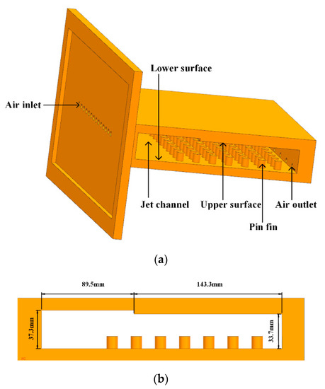
Figure 1.
Schematic of impingement cavity model. (unit: mm). (a) Impingement cavity model. (b) Size of impingement cavity.
The cold air passes through the impingement holes to the impingement cavity and carries out heat transfer on the lower surface. At the same time, the air flow is reflected and diffused to the upper surface for heat transfer, finally, the air flows out of the air outlet. The impingement holes and outlet holes are on the different side surfaces. There is an angle between them, ensuring that the air flow covers the impingement cavity better and improves heat transfer.
The numerical simulation model has 14 impingement holes with a hole diameter of 7.2 mm, and a hole spacing of 17.48 mm. There are 6 outlet holes with a diameter of 6.6 mm. The thickness of the impingement hole plate is 30 mm. The diameter of pin fin is 10.8 mm, the height of pin fin is 12 mm, and the number of pin fin is 12 × 7. The pin fins spacing in the horizontal and vertical is 23.4 mm. Figure 1b is the size of the impingement cavity.
The research results [35] show that the impingement cooling of the row arrangement of the pin fins is more significant than that of the staggered arrangement, and the comprehensive heat transfer efficiency is greatly improved. The investigation chooses the row arrangement of the pin fins.
2.2. Governing Equation
The following assumptions are made in the simulation calculation: (1) the flow is steady-state; (2) the fluid is continuous; (3) the fluid is incompressible; (4) there is no source term in the energy equation. Therefore, the governing equations of incompressible flow in the numerical simulation can be simplified:
Mass conservation equation:
where ∇ is gradient operators and V is the velocity vector.
Momentum conservation equation:
where ρ is air density, t is time, p is static pressure, τ is viscous stress and SM is dynamic source term.
Energy conservation equation:
where u is internal energy, λ is fluid thermal conductivity, T is fluid temperature, Φ is viscous dissipation function and q’ is heat flux.
2.3. Boundary Condition
Unstructured meshes are used in numerical simulation, which can make the boundary layer meshes denser. Figure 2 is the comparison of the average heat flux of the lower surface under three different mesh numbers. When the number of iterations reaches 1000, the heat flux on the lower surface begins to converge. When the number of meshes increases from 4.73 million to 6.96 million, the heat flux changes by 3%. When the number of them increases from 6.96 million to 8.52 million, the heat flux only changes by 0.28%. Finally, the number of simulation grids of the model is 6.96 million, as shown in Figure 3.
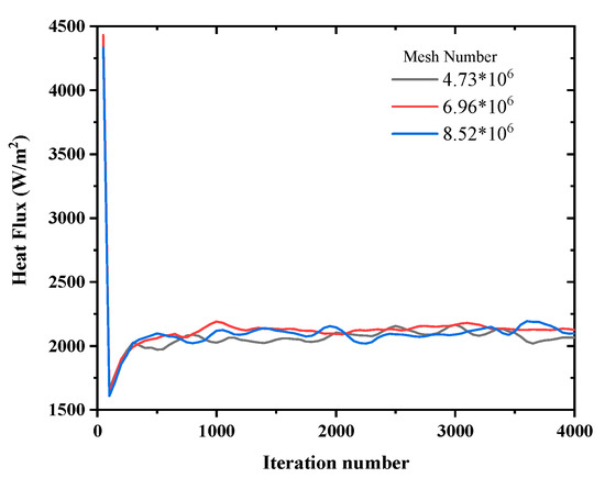
Figure 2.
Comparison of the average heat flux of the lower surface under three different mesh numbers.
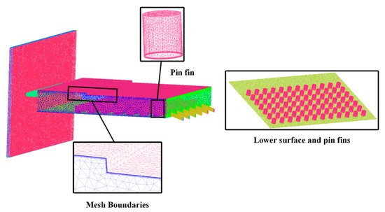
Figure 3.
Schematic mesh of numerical simulation model.
Since the Reynolds number range studied is mainly in the turbulent region, the numerical simulation adopts a realizable k-ε model, which has a high calculation accuracy in the turbulent region. Moreover, the realizable k-ε model can be extended to the calculation of transition zone. The discrete format used in this calculation is the second-order upwind discrete format, and the algorithm is simple algorithm, because they converge fast. The growth rate of the boundary layer in the simulation is 1.2. The residual standard of pressure, temperature, heat flux convergence is 1 × 10⁻⁵.
The air inlet is the mass flow inlet, and the temperature of inlet air flow T0 is 300 K. The air is an incompressible ideal gas. The air outlet is the pressure outlet. The upper and lower surface and the surface of pin fins are heated by constant temperature Tk is 340 K. Other walls are adiabatic and have no-slip boundary conditions.
2.4. Parameter Definition
The expressions of the parameters used in this paper are as follows.
Reynolds number:
where v is air velocity, D is impingement hole diameter and μ is hydrodynamic viscosity.
Heat transfer coefficient:
where q is local heat flow density, Tw is local wall temperature and T0 is local air flow temperature.
Nusselt number:
Flow resistance:
where Δp is static pressure difference, Dh is hydraulic diameter of jet channel and L is length of jet channel.
Hydraulic diameter of impact channel:
where Vt is volume of jet channel without pin fins, Vp is volume of pin fins and Af is effective heat transfer area of jet channel.
3. Results and Discussion
Under the condition that the cavity size, the diameter and number of outlet holes remain fixed, this research focuses on the effects of the number of impingement holes, the diameter of impingement hole, the pin fin height, the pin fin spacing and the pin fin shape on the heat transfer characteristics.
3.1. Verification of Numerical Simulation Method
The schematic of the experimental system is shown in Figure 4, which is composed of the blower, air tank, pressure regulator, flow regulator, discharge valve, electric heater, experimental unit and measuring instrument. The inlet air is compressed by the blower. Measure the pressure through inclined pipe differential pressure gauge and pressure digital display gauge. K-thermocouple and multi-channel temperature measuring instruments are used to measure the temperature for the pipeline and the experimental unit. The range of temperature measurement is −200~260 °C, and the accuracy of that is 0.4%. The flow is measured by an integrated ultrasonic mass flowmeter with a measuring range of 10~100 m³/h and an accuracy of 1%.
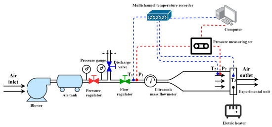
Figure 4.
Schematic of the experimental system.
Experimental measurement parameters such as temperature, temperature, pressure and rate of flow are related to the experimental results. In the experiments, the measurement errors of temperature, pressure and rate of flow are about 0.45%, 7.39%, and 7.39%, respectively. According to the error transfer principle, the experimental error is .
Take the impingement hole diameter of 6, 7.2 and 8.4 mm, respectively, for the experiment. Due to the limitation of the experimental devices working range, the Re range in the experiment is 8 × 10³~2 × 10⁴. Compare numerical simulation results of the average Nusselt number with experimental ones for the lower surface, and the results are shown in Figure 5. Under the same conditions, the numerical simulation results are consistent with the experimental ones. The heat transfer performance improves with the increase in the impingement hole diameter. The average error of the simulation results and the experimental results is about 15.83%. This includes the error between simulation results and real results, and the error between test results and real results. This is caused by the errors of experiments and simulation. The simulation method can be considered to be correct.
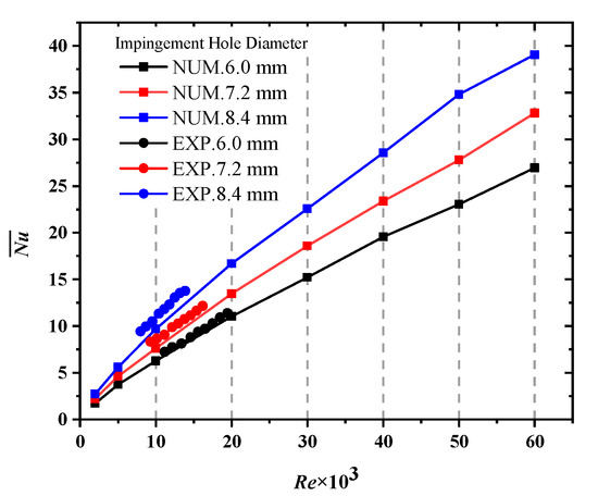
Figure 5.
Comparison of numerical simulation results of the average Nusselt number with experimental ones for the lower surface. ( is the average Nusselt number of surface).
3.2. Flow Field Distribution
The jet flow in the impingement cavity is closely related to the heat transfer. Figure 6 is the streamlines and Nu distribution with and without pin fins on the lower surface at Re = 2 × 10³, 14 impingement holes with a hole diameter of 7.2 mm.
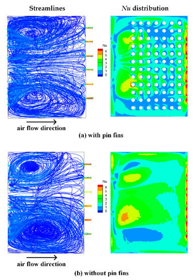
Figure 6.
Streamlines and Nu distribution with and without pin fins on the lower surface at Re = 2 × 10³.
Impinging jet flow directly affects the heat transfer in the cavity, and the Nu distribution on the lower surface corresponds to the streamline. The heat transfer near the outlet holes is good, while the heat transfer in the vortex area is poor. The impingement cavity is inclined, and the upper and lower surfaces of the impingement cavity have an angle of 32° with respect to the horizontal plane. So, there is less symmetric with respect to the flow direction, and the heat transfer at the below outlet is stronger than that at the above outlet. Comparing Figure 6a,b, the pin fins can make the heat transfer more uniform.
3.3. Effect of Impingement Hole
3.3.1. Effect of Impingement Hole Diameter
5 kinds of impingement hole diameters including 4.8 mm, 6.0 mm, 7.2 mm, 8.4 mm and 9.6 mm are investigated in this part. Figure 7 shows the average Nusselt number of the upper and lower surfaces with various impingement hole diameters at Re = 2 × 10³~6 × 10⁴. When the impingement hole diameter is constant, the average Nusselt number of the upper and lower surfaces increases with the increase in the Re. The increase in the Re indicates that the air jet velocity at the inlet of the impingement holes increases, the impact is more intense, and the Nu of the surfaces increases accordingly.
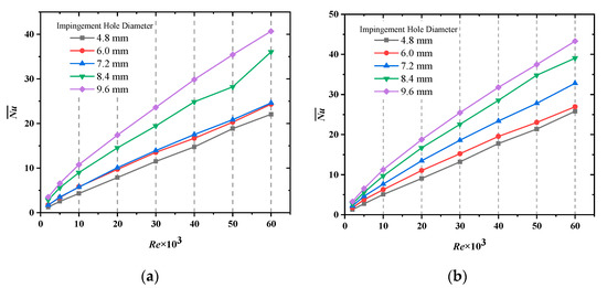
Figure 7.
Comparison of the average Nusselt number of (a) the upper surface and (b) the lower surface under various impingement hole diameters.
In the range of 4.8 mm~9.6 mm, the larger the impingement hole diameter, the larger the average Nusselt number of the upper and lower surfaces. Among the five kinds of hole diameters studied, the impingement cooling effect with 9.6 mm is the best. When the impingement hole diameters are 6.0 mm, 7.2 mm, 8.4 mm and 9.6 mm, the average Nusselt number of the upper surface is increased by 22.3%, 24.2%, 86.6% and 123.6% compared with 4.8 mm. The average Nusselt number of the lower surface is increased by 19.3%, 46.2%, 79.6% and 104.3%, respectively.
The increase in the impingement hole diameter leads to the reduction in the jet velocity, which makes the Nu decrease. However, when the impingement hole diameter increases, the coverage area of the impingement flow increases and the turbulence intensity in the impingement superposition region increases, which will improve the impingement cooling of the cavity. From the results, the influence of increasing the coverage area is greater than that of reducing the jet velocity.
In addition, it is found that when Re and the impingement hole diameter are constant, the average Nusselt number of the lower surface is higher than that of the upper surface by comparing Figure 7a,b. Because the pin fins on the lower surface can directly improve the impingement cooling, while the upper surface is mainly cooled by air reflux.
Figure 8A,B are Nu distribution of the upper and lower surfaces at Re = 2 × 10⁴ under different impingement hole diameters. At the same Re, the larger the impingement hole diameter, the larger the high Nu area, that is, the impingement cooling improves obviously. With the increase in the hole diameter, the maximum Nu on the lower surface increases, but the minimum decreases. When the hole diameter is 9.6 mm, the maximum Nu is 84.403 and the minimum Nu is 0.095. That is, there is almost no cooling and heat transfer in the local area, which may occur ablation.
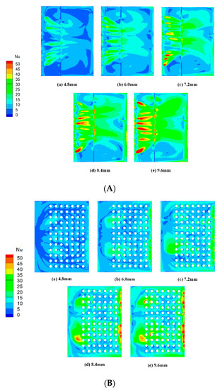
Figure 8.
Nu distribution of (A) the upper surface and (B) the lower surface under different impingement hole diameters at Re = 2 × 10⁴.
With the increase in the impingement hole diameter, Nu on the upper surface near the impingement holes increases significantly, while it is evenly distributed on the lower surface. Pin fins on the lower surface make the heat transfer more uniform, and the upper surface is smooth and unobstructed. The Nu of the cavity boundary area is small and the temperature is relatively high, where may produce local ablation.
Figure 9a,b show the Nu distribution curves of the upper and lower surfaces along the proposed geometry at Re = 2 × 10³ under the impingement hole diameter of 7.2 mm. In Figure 9a, on the upper surface, the air flow is reflected and diffused, the upstream region is directly impacted by the cooling air flow, the Nu in this region is high. Near the step and outlet, the turbulence intensity of air flow increases and the heat transfer is strengthened. In Figure 9b, on the lower surface, the heat transfer is more uniform on the lower surface than that on the upper surface because of the pin fins.
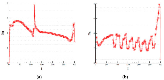
Figure 9.
Nu distribution curves of (a) the upper surface and (b) the lower surface under impingement hole diameter of 7.2 mm at Re = 2 × 10³.
Enhanced heat transfer is accompanied by a corresponding pressure drop, so the pressure drop should also be considered when realizing a better heat transfer effect. Figure 10 is a comparison of frictional resistance under various impingement hole diameters. The larger the impingement hole diameter, the greater the flow resistance. The Re has little effect on the flow resistance when the impingement hole diameter is small. The pressure drop of the impingement cavity with the impingement hole diameter of 4.8 mm is the smallest. Compared with it, the flow resistance with the hole diameter of 6.0 mm, 7.2 mm, 8.4 mm and 9.6 mm is increased by 39.7%, 123.5%, 251.7% and 459.3%, respectively.
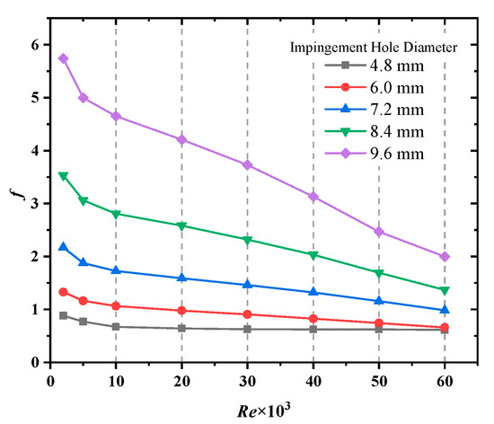
Figure 10.
Comparison of frictional resistance under various impingement hole diameters.
The average Nusselt number of the lower surface with the impingement holes diameter of 7.2 mm increases by 46.2% compared with the hole diameter of 4.8 mm. That of 7.2 mm decreases by 28.1% compared with that of 9.6 mm. The flow resistance of the impact cavity with a hole diameter of 7.2 mm is 123.5% higher than that of 4.8 mm. That of 7.2 mm is 59.1% lower than that of 9.6 mm. Considering the heat transfer and pressure loss, the impingement holes diameter can be selected as 7.2 mm.
3.3.2. Effect of Impingement Hole Number
9 kinds of impingement hole numbers including 1, 2, 4, 6, 8, 10, 12, 14 and 16 are investigated in this part. The average Nusselt number of the lower surface under various impingement hole numbers at Re = 2 × 10³~6 × 10⁴ is shown in Figure 11. In the range of 1~16, the more the impingement hole number, the larger the average Nusselt number of the lower surface. Since the distribution area of the impingement hole is fixed, the range of hole number arranged is limited. The impingement cooling effect with 16 is the best among nine kinds of hole numbers. When the impingement hole number are 2, 4, 6, 8, 10, 12, 14 and 16, the average Nusselt number of the lower surface are increased by 53.1%, 143.7%, 230.8%, 309.8%, 362.7%, 397.4%, 436.5% and 553.9% compared with one impingement hole.
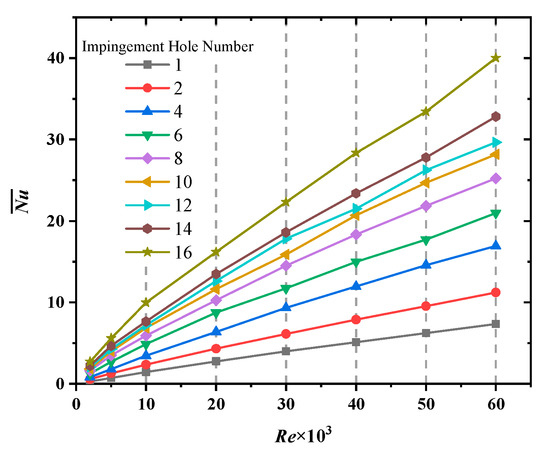
Figure 11.
Comparison of the average Nusselt number of the lower surface under various impingement hole numbers.
Because the impingement holes are distributed in the fixed area, the increase in the number of impingement holes increases the coverage area of the cooling jet and makes the heat transfer more uniform, which improves the overall heat transfer effect.
Figure 12 is Nu distribution of the lower surface at Re = 2 × 10⁴ under different impingement hole numbers.
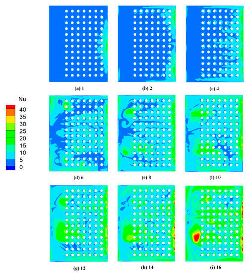
Figure 12.
Nu distribution of the lower surface under different impingement hole numbers at Re = 2 × 10⁴.
At the same Re, the more the impingement hole number, the more uniform the Nu distribution and the larger the high Nu area, that is, the impingement cooling improves obviously. The maximum Nu on the lower surface increases with the increase in the hole number. When the hole number is 16, the maximum Nu is 68.362. The minimum Nu is 0.002 when there is one impingement hole, that is, there is basically no cooling and heat transfer in some parts where may produce local ablation. When the number of impingement holes is little, the local temperature is easy to be too high, resulting in local ablation.
Figure 13 is a comparison of frictional resistance under various impingement hole numbers. The more the impingement hole number, the greater the flow resistance. The Re has little effect on the flow resistance when the impingement hole number is little. The pressure drop of the impingement cavity with one impingement hole is the smallest. Compared with it, the flow resistance with the hole number of 2, 4, 6, 8, 10, 12, 14 and 16 are increased by 3.95%, 22.9%, 52.4%, 92.7%, 141.5%, 200.8%, 258.9% and 444.2%, respectively.
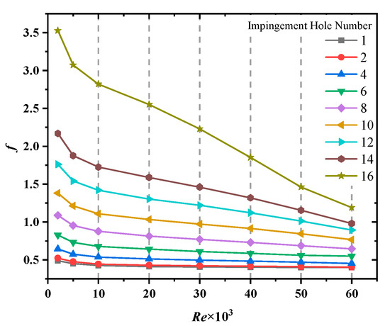
Figure 13.
Comparison of the frictional factor under various impingement hole numbers.
The average Nusselt number of the lower surface with 14 impingement holes increases by 436.5% compared with one impingement hole. That with 14 impingement holes decreases by 17.9% compared with 16 impingement holes. The flow resistance of the impingement cavity with 14 impingement holes is 258.9% higher than that with one impingement hole. That with 14 impingement holes is 31.9% lower than that with 16 impingement holes. Considering the heat transfer and pressure drop, the number of the impingement hole can be selected as 14.
3.4. Effect of Pin Fin
3.4.1. Effect of Pin Fin Height
6 kinds of pin fin heights including 0 mm, 3 mm, 6 mm, 12 mm, 18 mm and 24 mm are investigated in this part. The average Nusselt number of the lower surface under various pin fin heights at Re = 2 × 10³~6 × 10⁴ is shown in Figure 14. Due to the limitation of impingement cavity thickness, the pin fin height only includes 0 mm~24 mm. The higher the pin fin height, the smaller the average Nusselt number of the lower surface generally. Among the five kinds of pin fin heights investigated, the impingement cooling effect of 3 mm is the best. Compared with the pin fin height of 24 mm, the average Nusselt number of the lower surface with that of 3 mm is increased by 11.2%.
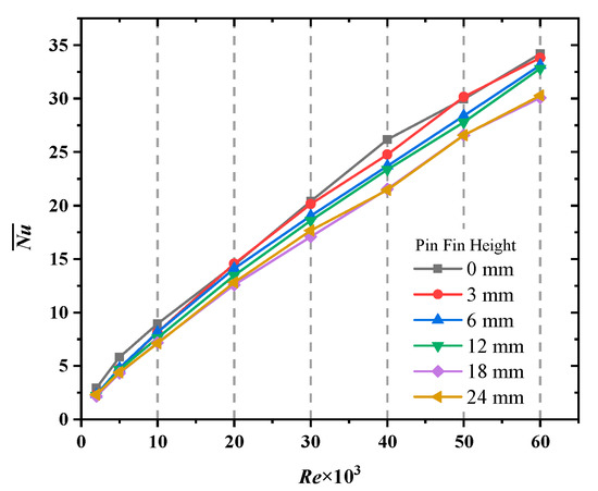
Figure 14.
Comparison of the average Nusselt number of the lower surface under various pin fin heights.
As the pin fin height increases, the air flow space decreases, and the probability of mutual collision and loss increases. Moreover, the increase in the pin fin height will cause the air flow to roll over and climb, which will reduce the cooling effect on the surfaces of the impingement cavity.
Figure 15 is Nu distribution of the lower surface at Re = 2 × 10⁴ under different pin fin heights. It can be found that when the pin fin height is 3 mm, the area of high Nu area is the largest, and the distribution is more uniform than that without pin fins. The pin fins can improve the heat transfer area where the Nu is too small, which is beneficial to avoid ablation. At this time, the maximum Nu on the lower surface reaches 62.74, which is greater than that of other pin fin heights.
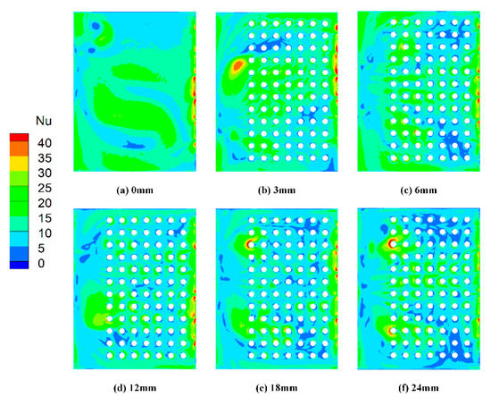
Figure 15.
Nu distribution of the lower surface under different pin fin heights at Re = 2 × 10⁴.
It is found that there is little difference between the average Nusselt number of the lower surface without pin fins and that with pin fin height of 3 mm by the above research. The pressure drop also needs to be considered when selecting the appropriate pin fin height.
Figure 16 is a comparison of frictional resistance under various pin fin heights. The pin fin height gets lower, the flow resistance increases and the pressure drop increases. The pin fins can buffer the reduction in the velocity of impingement air flow, so the pressure drop for the impingement cavity with pin fins is smaller than that without pin fins.
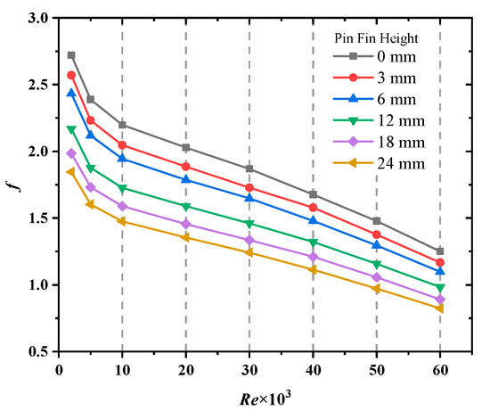
Figure 16.
Comparison of the frictional factor under various pin fin heights.
The flow resistance of the impingement cavity with the pin fin height of 3 mm is 40.1% higher than that with the pin fin height of 24 mm. That of 3 mm is 6.6% lower than that without pin fins. Considering the heat transfer and pressure drop, the pin fin height can be selected as 3 mm.
3.4.2. Effect of Pin Fin Spacing
It studied the effect of the pin fin spacing on the heat transfer at the pin fin height of 3 mm. Five kinds of pin fin spacings including 18.6 mm, 21.0 mm, 23.4 mm, 25.8 mm and 28.2 mm are investigated in this part. The average Nusselt number of the lower surface under various pin fin spacings at Re = 2 × 10³~6 × 10⁴ is shown in Figure 17. Figure 18 is Nu distribution of the lower surface at Re = 2 × 10⁴ under different pin fin spacings.
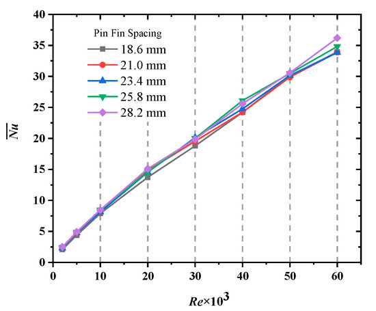
Figure 17.
Comparison of the average Nusselt number of the lower surface under various pin fin spacings.
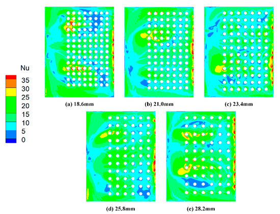
Figure 18.
Nu distribution of the lower surface under different pin fin spacings at Re = 2 × 10⁴.
When the pin fin spacing is 25.8 mm, the maximum Nu on the lower surface is 56.948, which is the largest among the five spacings. Combined with Figure 17 and Figure 18, there is little difference in the heat transfer in the range of 18.6 mm~28.2 mm. Small spacing can hinder airflow and increase viscous dissipation, which is more obvious at high Re than that at low Re. At high Re, the impingement cooling effect of large pin fin spacing is better than that of small pin fin spacing.
Figure 19 is a comparison of frictional resistance under various pin fin spacings. The larger the pin fin spacing, the greater the flow resistance and the pressure drop. The average Nusselt number of the lower surface with the pin fin spacing of 25.8 mm increases by 7.5% compared with that of 18.6 mm. That of 25.8 mm decreases by 1.1% compared with that of 18.6 mm. The flow resistance of the impingement cavity with the pin fin spacing of 25.8 mm is 3.5% higher than that of 18.6 mm. That of 25.8 mm is 1.5% lower than that of 28.2 mm. Considering the heat transfer and pressure drop, the pin fin spacing can be selected as 25.8 mm.
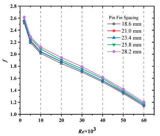
Figure 19.
Comparison of the frictional factor under various pin fin spacings.
3.4.3. Effect of Pin Fin Shape
The reference model has the circular pin fin, and this research chooses two kinds of elliptical pin fins for comparison. Two kinds of pin fins are shown in Figure 20. The major axis of the elliptical I pin fin is parallel to the air flow direction, and that of elliptical II is vertical to the air flow direction. The major diameter of the two kinds of elliptical pin fins is 10.8 mm, which is the same as the diameter of the circle pin fin. The minor diameter is 5.4 mm, which is the same as the radius of the circle pin fin.
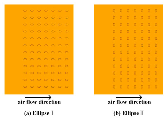
Figure 20.
Schematic of two kinds of elliptic pin fins.
The average Nusselt number of the lower surface under various pin fin shapes at Re = 2 × 10³~6 × 10⁴ is shown in Figure 21. At the low Re, there is little difference in the average Nusselt number on the lower surface under three-pin fin shapes. When Re increases to 3 × 10⁴, the average Nusselt number of the lower surface with circle and elliptical I pin fins exceeds that of elliptical II pin fins. Because the windward side of the elliptical II pin fin is large, which hinders the air flow, and increases the turbulence intensity.
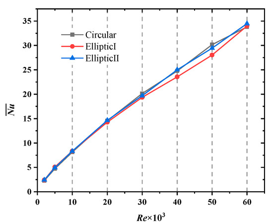
Figure 21.
Comparison of the average Nusselt number of the lower surface under various pin fin shapes.
Shown in Figure 22 is Nu distribution of the lower surface at Re = 2 × 10⁴ under different pin fin shapes. The maximum Nu on the lower surface with elliptical I pin fins is 56.171. It is the largest among the three shapes, followed by the circle.
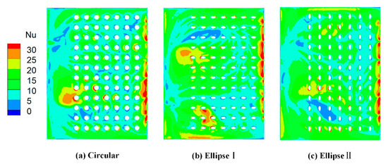
Figure 22.
Nu distribution of the lower surface under different pin fin shapes at Re = 2 × 10⁴.
Figure 23 is a comparison of frictional resistance under three kinds of pin fin shapes. The flow resistance of the impingement cavity with elliptical pin fins are 3.9% higher than that with circle pin fins. Considering the heat transfer and pressure drop, a circle pin fin can be selected.
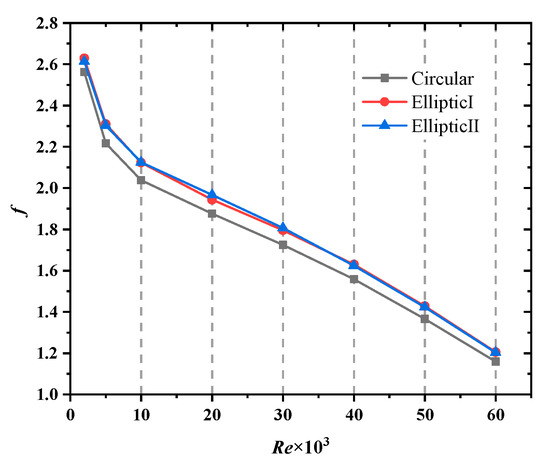
Figure 23.
Comparison of the frictional factor under various pin fin shapes.
3.5. Entropy Generation in Impingement Cooling
In the process of impingement cooling heat transfer, the entropy generation of air flow will be produced. In this study, the air is considered as the ideal gas and the heat loss is neglected. The entropy generation in the adiabatic process for the ideal gas can be defined as:
where, Cp is the isobaric specific heat capacity; γ is the specific heat ratio, taken as 1.3; Pref and Tref are the reference pressure and temperature, taking Pref and Tref as the total pressure and temperature at the inlet of impingement cavity, respectively; P and T are the pressure and temperature at any point in the flow field.
Figure 24 is one case of the entropy generation distribution with pin fins on the lower surface when Re is 2 × 10⁴, impingement hole number is 14 and the hole diameter is 7.2 mm. It can be seen from the figure that after the air flow passes through the impingement holes, the air flow area and the air mixing degree increase, so the entropy generation near the inlet is large; near the outlet holes, the air flow shrinks and the air flow area decreases suddenly, so the entropy generation near the outlet holes is large; in the region of the pin fins, for the pin fins are arranged orderly, the entropy generation is relatively uniform.
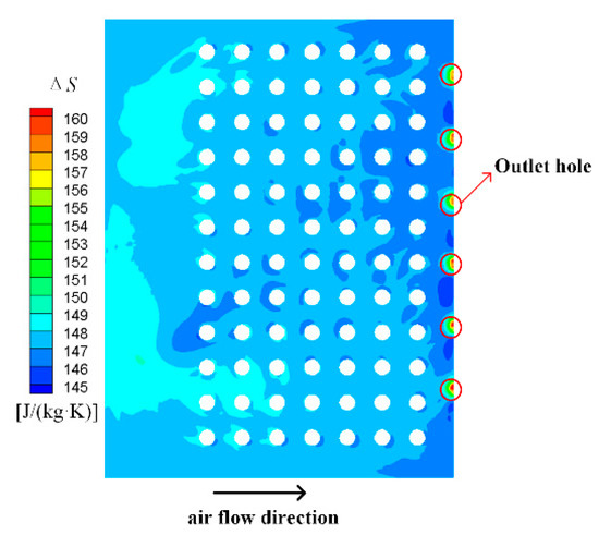
Figure 24.
Entropy generation distribution with pin fins on the lower surface at Re = 2 × 10⁴.
4. Conclusions
In order to strengthen the impingement cooling heat transfer in the end wall cavity of the gas turbine guide vane, its structure and parameters have constantly been improved. This study investigates the effects of the impingement hole diameter, the impingement hole number, and the height, spacing and shape of pin fins on the impingement cooling. The key findings of this research are as follows.
- The larger the Re, the larger the average Nusselt number of the upper and lower surfaces, and the average Nusselt number of the lower surface is larger than that of the upper surface.
- With the increase in the impingement hole diameter, the average Nusselt numbers of the upper and lower surfaces are both increased, and the minimum Nu of the lower surface is reduced, where may produce local ablation. The higher the number of impingement holes, the larger the average Nusselt number of the lower surface, the more uniform the Nu distribution. It is recommended to use 14 impingement holes with a hole diameter of 7.2 mm.
- The geometric parameters of the pin fin have less effect on heat transfer and pressure drop. Compared with the pin fin height is 24 mm, the average Nusselt number of the lower surface only improved by 11.2% when the pin fin height is 3 mm. The average Nusselt number of the lower surface with the circular pin fin is larger than that of the elliptical pin fin, and its flow resistance is smaller. It is recommended to use the circular pin fin with a height of 3 mm and spacing of 25.8 mm.
- The jet flow in cavity is closely related to the heat transfer. The heat transfer near the impingement holes is better, while the heat transfer in the vortex area is poor. Due to the turbulence effect of the pin fins, the air flow turbulence intensity increases rapidly, and heat transfer is enhanced.
Author Contributions
Conceptualization, L.Z.; methodology, L.Z. and G.C.; software, G.C. and K.F.; validation, L.Z., G.C. and K.F.; formal analysis, G.C. and K.F.; investigation, G.C., K.F. and Y.J.; data curation, Y.J. and Z.Z.; writing—original draft preparation, G.C. and L.Z.; writing—review and editing, L.Z. and G.C.; visualization, Z.Z.; supervision, L.Z. All authors have read and agreed to the published version of the manuscript.
Funding
This research received no external funding.
Institutional Review Board Statement
Not applicable.
Informed Consent Statement
Not applicable.
Conflicts of Interest
The authors declare no conflict of interest.
References
- Musa, M.N.; Khalid, M. Jet Impingement Cooling System on the Pressure Side of Turbine Vane. Appl. Mech. Mater. 2015, 695, 503–507. [Google Scholar] [CrossRef]
- Kumar, S.; Amano, R.S. An Investigation in the Numerical Approach to Solve the Heat Transfer Phenomenon in Gas Turbine. J. Energy Resour. Technol. 2021, 143, 1–23. [Google Scholar] [CrossRef]
- Patill, C.R.; Dandotiya, D.; Pal, B.; Banker, N. Numerical Investigation of Heat Transfer in Aircraft Engine Vane Using k-ε and SST k-ω Model. IOP Conf. Ser. Mater. Sci. Eng. 2021, 1013, 012027. [Google Scholar] [CrossRef]
- Ortega-Casanova, J.; Granados-Ortiz, F.J. Numerical simulation of the heat transfer from a heated plate with surface variations to an impinging jet. Int. J. Heat Mass Transf. 2014, 76, 128–143. [Google Scholar] [CrossRef]
- Tejero, F.; Flaszyński, P.; Szwaba, R.; Telega, J. Unsteady conjugate heat transfer analysis for impinging jet cooling. J. Phys. Conf. Ser. 2016, 760, 012034. [Google Scholar] [CrossRef] [Green Version]
- Xi, L.; Gao, J.M.; Xu, L.; Zhao, Z. Numerical Study on Flow and Heat Transfer Characteristics of Jet Array Impingement Cooling in Turbine Vane Leading Edge. J. Eng. Thermophys. 2021, 42, 430–437. [Google Scholar]
- Haider, S.A.; Yan, X.T. Jet Diameter Effect on Impingement Jet Cooling on the Leading Edge of a Turbine Vane. In Proceedings of the 54th AIAA Aerospace Sciences Meeting, San Diego, CA, USA, 4–8 January 2016; p. 0905. [Google Scholar]
- Zhou, J.F.; Wang, X.F.; Li, J. Influences of effusion hole diameter on impingement/effusion cooling performance at turbine vane leading edge. Int. J. Heat Mass Transf. 2019, 134, 1101–1118. [Google Scholar] [CrossRef]
- Zhou, J.F.; Wang, X.F.; Li, J.; Li, Y.D. Effects of film cooling hole locations on flow and heat transfer characteristics of impingement/effusion cooling at turbine vane leading edge. Int. J. Heat Mass Transf. 2018, 126 Pt. B, 192–205. [Google Scholar] [CrossRef]
- Xie, G.; Liu, C.L.; Ye, L.; Wang, R.; Niu, J.J.; Zhai, Y.N. Effects of impingement gap and hole arrangement on overall cooling effectiveness for impingement/effusion cooling. Int. J. Heat Mass Transf. 2020, 152, 119449. [Google Scholar] [CrossRef]
- Abdulla, R.; Al, A.; Isam, J. Numerical Simulation of Turbine Vane Cooling via Jet Impingement. Energy Procedia 2015, 75, 3220–3229. [Google Scholar]
- Zhu, X.W.; Zhu, L.; Zhao, J.Q. An in-depth analysis of conjugate heat transfer process of impingement jet. Int. J. Heat Mass Transf. 2017, 104, 1259–1267. [Google Scholar] [CrossRef]
- Prasanth, A.K.L.; Prakash, K.A. A numerical investigation and design optimization of impingement cooling system with an array of air jets. Int. J. Heat Mass Transf. 2017, 108 Pt A, 880–900. [Google Scholar]
- Yan, H.J.; Chen, G.J.; Rao, Y. Experiment on Flow and Heat Transfer of Impingement-Film Cooling for Leading Edge of Turbine Vane. J. Eng. Thermophys. 2020, 41, 2970–2976. [Google Scholar]
- Neil, J.C.; Wright, L.M.; Crites, D.C. Impingement Heat Transfer on a Cylindrical, Concave Surface with Varying Jet Geometries. J. Heat Transf. 2016, 138, 122202. [Google Scholar] [CrossRef]
- Harrington, J.; Hossain, J.; Wang, W.P.; Kapat, J.; Maurer, M.; Thorpe, S. Effect of Target Wall Curvature on Heat Transfer and Pressure drop From Jet Array Impingement. J. Turbomach. 2017, 139, 051004. [Google Scholar] [CrossRef]
- Rim, B.K.; Sabra, H.; Nejla, M.S.; Hervé, B.; Georges, L.P. Parametric analysis of a round jet impingement on a heated plate. Int. J. Heat Fluid Flow 2016, 57, 11–23. [Google Scholar]
- Hamed, S.; Shahab, M.; Moham-madkazem, S.; Mehdi, A. Experimental and numerical study on heat transfer characterist-ics of various geometrical arrangement of impinging jet arrays. Int. J. Therm. Sci. 2016, 102, 26–38. [Google Scholar]
- Antonio, A.; Lorenzo, C.; Bruno, F.; Lorenzo, M.; Alessio, P. Experimental and numerical investigation on the role of holes arrangement on the heat transfer in impingement/effusion cooling schemes. Int. J. Heat Mass Transf. 2018, 127 Pt A, 645–659. [Google Scholar]
- Dushyant, S.; Premachandran, B.; Sangeeta, K. Experimental and numerical investigation of jet impingement cooling of a circular cylinder. Int. J. Heat Mass Transf. 2013, 60, 672–688. [Google Scholar]
- Han, J.C.; Dutta, S.; Ekkad, S. Gas Turbine Heat Transfer and Cooling Technology; CRC Press: Boca Raton, FL, USA, 2012. [Google Scholar] [CrossRef]
- Lu, X.F.; Li, W.H.; Li, X.Y.; Ren, J.; Jiang, H.D. Influences of Micro Pin-Fin on Jet Array Impingement Heat Transfer. J. Eng. Thermophys. 2018, 39l, 1447–1452. [Google Scholar]
- Guo, Z.Q.; Li, Y.L.; Rao, Y. Flow and Heat Transfer Characteristics in Multi-pass Channel Cooling Structure with Ribs and Turning Vanes of Turbine Vanes. J. Eng. Thermophys. 2020, 41, 2225–2232. [Google Scholar]
- Li, W.H.; Ren, J.; Jiang, H.D.; Luan, Y.G.; Ligrani, P. Assessment of six turbulence models for modeling and predicting narrow passage flows, part 2: Pin fin arrays. Numer. Heat Transf. Part A Appl. 2016, 69, 445–463. [Google Scholar] [CrossRef]
- Jia, N.; Jin, W.; Wu, J.M.; Lei, J.; Ji, W.T. Numerical investigation on flow and heat transfer of beveled pin fins based on airfoil profile in a cooling channel. J. Aerosp. Power 2021, 36, 61–69. [Google Scholar]
- Siw, S.C.; Fradeneck, A.D.; Chyu, M.K. The Effects of Different Pin-Fin Arrays on Heat Transfer and Pressure drop in a Narrow Channel. In Proceedings of the ASME Turbo Expo 2015: Turbine Technical Conference and Exposition, Montreal, QC, Canada, 15–19 June 2015. [Google Scholar]
- He, Y.G.; Guo, Z.J.; Li, R.D.; Li, S.B.; Yang, T.H. Numerical Simulation of Efficiency Index of Impingement Cooling System with Different Pin Fins Shapes. J. Propuls. Technol. 2019, 40, 624–634. [Google Scholar]
- Ravanji, A.; Rajabi, Z.M. Effects of pin-fin shape on cooling performance of a circular jet impinging on a flat surface. Int. J. Therm. Sci. 2020, 161, 106684. [Google Scholar] [CrossRef]
- Chen, L.L.; Robin, G.A.; Brakmann, B.W.; Jose, R.; Michael, C.; Rico, P. Experimental and numerical heat transfer investigation of an impingement jet array with V-ribs on the target plate and on the impingement plate. Int. J. Heat Fluid Flow 2017, 68, 126–138. [Google Scholar] [CrossRef]
- Phillip, M.L.; Ren, Z.; Warren, C.B. Impingement jet array heat transfer with small-scale cylinder target surface roughness arrays. Int. J. Heat Mass Transf. 2017, 107, 895–905. [Google Scholar]
- Ravi, S.J.; Balaji, C. Fluid flow and heat transfer characteristics of a vertical channel with detached pin-fin arrays arranged in staggered manner on two opposite endwalls. Int. J. Therm. Sci. 2016, 105, 57–74. [Google Scholar]
- Rao, Y.; Wan, C.Y.; Xu, Y.M. An experimental study of pressure drop and heat transfer in the pin fin-dimple channels with various dimple depths. Int. J. Heat Mass Transf. 2012, 55, 6723–6733. [Google Scholar] [CrossRef]
- Bianco, N.; Iasiello, M.; Mauro, G.M.; Pagano, L. Multi-objective optimization of finned metal foam heat sinks: Tradeoff between heat transfer and pressure drop. Appl. Therm. Eng. 2021, 182, 116058. [Google Scholar] [CrossRef]
- Li, Y.T.; Gong, L.; Xu, M.H.; Joshi, Y. Thermal Performance of Metal Foam Heat Sink with Pin Fins for Nonuniform Heat Flux Electronics Cooling. J. Electron. Packag. 2021, 143, 011006. [Google Scholar] [CrossRef]
- Rao, Y.; Chen, P.; Wan, C.Y. Experimental and numerical investigation of impingement heat transfer on the surface with micro W-shaped ribs. Int. J. Heat Mass Transf. 2016, 93, 683–694. [Google Scholar] [CrossRef]
Publisher’s Note: MDPI stays neutral with regard to jurisdictional claims in published maps and institutional affiliations. |
© 2021 by the authors. Licensee MDPI, Basel, Switzerland. This article is an open access article distributed under the terms and conditions of the Creative Commons Attribution (CC BY) license (https://creativecommons.org/licenses/by/4.0/).