1. Introduction
With the increasing complexity of product structures in industry fields, such as automobile, machine tools, and aerospace, the quality consistency and machining accuracy of key parts is constantly improving, and high-performance tool products are urgently needed to meet machining needs. End milling cutters have attracted the attention of scholars because of their good processing quality, processing efficiency, and economical efficiency [
1,
2]. Their dynamic characteristic are the key factor affecting the quality of milling. The structure design of an end milling cutter, based on dynamic characteristics, is the key to improve machining quality and machining efficiency and reduce machining costs [
3,
4,
5].
The conventional end milling cutter can easily cause vibrations and affect the machining quality and efficiency because the milling force waveforms of each cutter tooth are exactly the same [
6]. In order to improve tool performance, Slavicek [
7] came up with the idea of a variable pitch end milling cutter in 1965. It was found that an irregular tooth end milling cutter can obviously reduce vibrations in the milling process. Since then, research on the structural design and dynamic characteristics of irregular tooth end milling cutter has been widely performed by scholars. Tu [
8] found that an end milling cutter with a variable helix could reduce workpiece deformation more effectively than the variable pitch end milling cutter. Budak [
9] put forward a new structural design method based on the optimization of a pitch angle distribution of an irregular tooth end milling cutter, and experiments showed that a reasonably designed irregular tooth end milling cutter can improve stability in the milling process. Olgac et al. [
10] used the eigenvalue clustering method to analyze the stable and unstable boundaries, and this mathematical method could obtain a more reasonable pitch angle distribution and cutting parameters. Ahmad et al. [
11] used two algorithms to optimize the angle of a variable helix end milling cutter to suppress flutter. Through the above research, it was found that the milling stability of the irregular tooth end milling cutter is better than that of the ordinary end milling cutter, and the machining quality of the parts could be effectively improved by optimizing the structure design of the irregular tooth end milling cutter.
However, the structure of the variable pitch angle and helix angle will lead to an uneven mass distribution of the irregular tooth end milling cutter, which will lead to its poor stability compared with some high-performance equal pitch and helix end milling cutters in high-speed milling [
12]. Therefore, the eccentricity and centroid distribution caused by the asymmetric structure of the irregular tooth end milling cutter cannot be ignored [
13,
14]. Our team put forward a helical flute design method for irregular tooth end milling cutters, based on dynamic balance accuracy, which aims at minimum eccentricity and eliminates the principle error of dynamic balance design caused by uneven distributions of cutter pitch, as shown in
Figure 1 [
15]. The overall eccentricity of the end milling cutter approaches infinitesimal. According to the formula of unbalancing of rotating body and accuracy of dynamic balance:
where
U is the unbalanced amount of the revolving body (kg·mm);
m is the mass of the revolving body (kg);
e is the mass eccentricity of the rotor (mm);
n is the rotation speed (rpm).
G is the dynamic balance accuracy (mm/s) [
16]. When the eccentricity approaches infinitesimal, a higher dynamic balance accuracy can be achieved and the cutting stability can be improved. However, whether the centroid distribution of the irregular tooth end milling cutter with an equal overall eccentricity is the same or not, as well as the influence of the centroid distribution of the irregular tooth end milling cutter on the tool vibration characteristics and dynamic performance are rarely mentioned by scholars and need to be studied further.
Finite element analysis has been continuously developed and improved since the 1960s. It has attracted a great deal of attention from scholars because of its high degree of reduction and accurate calculations [
17,
18,
19]. Modal analysis and harmonic response analysis are two commonly used and effective methods for investigation of the dynamic characteristics of tools [
20]. Modal analysis aims to discretize the vibration problem of an elastic continuum into a multi-degree-of-freedom system with finite node displacements as a generalized coordinate system [
21]. Harmonic response analysis is mainly based on the excitation of the external load, and then the response of the structure under the excitation is determined, which provides an important reference for the dynamic characteristic analysis and structural optimization of the structure [
22]. The advantages of the finite element method in the process of tool research and development are as follows: (a) using finite element method to analyze and predict the natural frequency, vibration mode, and stiffness of cutting tools can reduce the number of tests on the finished products and effectively reduce the research and development cycle; (b) data information, which are inconvenient to collect from the actual machining process can be obtained by analyzing the dynamic characteristics of the cutting tool through simulations; (c) the finite element simulation makes data generation more intuitive, convenient, and accurate, and reduces the cost of research and development [
23]. Yen et al. [
24] established cemented carbide tool models, with and without coatings, and performed finite element simulation analyses to conclude that cemented carbide tools with coatings can reduce the cutting force and cutting temperature. Kivanc et al. [
25] carried out modal analyses of a milling cutter and milling system components, and proposed generalized equations for predicting static and dynamic characteristics of milling system components. Zhai [
26] conducted finite element modal analyses on an insert milling cutter, and concluded that the total deformation of the cutter was minimal when the axial front angle and radial front angle of the cutter are 5° and −5°, respectively, and the working frequency reached 10,012 HZ. Vytautas et al. [
27] analyzed the harmonic response of tools with different lengths using the finite element method, and found that the excitation of specific tool modes was the prerequisite for realizing the maximum efficiency of the vibration milling process. Delporta [
28] used the finite element method to study the suppression effects of two different clamps on the deformation of TC4 thin-walled parts, and the conclusion proved that the total deformation of parts was reduced by 24.3% and the maximum principal stress was reduced by 61.5% using the clamping fixture. It can be seen that the use of the finite element method to explore the dynamic characteristics of irregular tooth end milling cutter is an effective research method.
In summary, scholars have accomplished some research achievements on flutter suppression mechanism and the design criteria of irregular tooth end milling cutters, such as angle design optimization, milling force waveform, mass eccentricity, and so on. Through previous studies, it can be known that reducing mass eccentricity makes the centroid of the end milling cutter approach the infinitesimal, which can effectively solve the problem of the dynamic characteristics of irregular tooth end milling cutters being limited by their structure. However, it is not known whether the structural design of the irregular tooth end milling cutter has an effect on the centroid distribution, whether the centroid distribution is the same, or whether the centroid distribution affects the dynamic characteristics of the end milling cutter. Therefore, according to the parameterized design of a helical flute on the end face of an end milling cutter, this paper deduces a general mathematical model for calculating the centroid of an irregular tooth end milling cutter, and calculates the position coordinates of the centroid in each section for four types of end milling cutters (A-type variable pitch-variable helix, B-type variable pitch-equal helix, C-type equal pitch-variable helix, and D-type equal pitch-equal helix). It provides a theoretical basis for subsequent research on the centroid distribution of end milling cutters. The centroid distribution of all types of end milling cutters with the same overall eccentricity and different structure is investigated and analyzed. The influence of the tool structure on the dynamic characteristics of a milling cutter is studied using finite element analysis with ABAQUS and ANSYS software. The natural frequency and mode shape of each type of end milling cutter are obtained through modal analyses. Under the same dynamic excitation, the resonance frequency band of four types of end milling cutters and the response displacement of each type of end milling cutter are obtained by harmonic response analysis. Under the premise of fixing the overall eccentricity of the tool, the influence of the tool structure on centroid distribution and dynamic performance is explored. This provides a theoretical reference for the accurate design of an irregular tooth end milling cutter, and this research content is a meaningful exploration.
3. Study on Centroid Distribution of End Milling Cutter
3.1. Geometric Model of End Milling Cutter
The irregular tooth end milling cutter can be divided into variable pitch variable helix, variable pitch equal helix, and equal pitch variable helix. In this section, the centroid distribution of irregular tooth end milling cutters and equal pitch equal helix end milling cutter with equal eccentricity are presented.
3.1.1. Model of Irregular Tooth End Milling Cutter
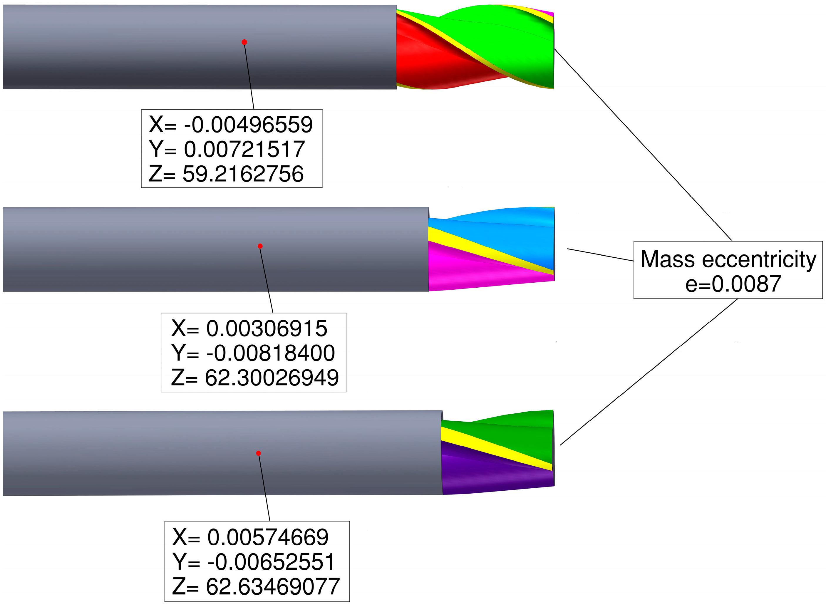
The geometric model of irregular tooth end milling cutters was established on the premise of ensuring that the overall quality eccentricity, pitch difference angle, helix difference angle, full length, bar diameter, tool material, core thickness, and other parameters of the end milling cutter are consistent. Because the influence of design details, such as rear angle, cutting edge, and chamfer, on the research content of this paper is negligible, the structure of the end milling cutter can be reasonably simplified, as shown in
Figure 4, where
X,
Y, and
Z are the coordinates of the overall centroid position of the tool.
3.1.2. Model of Equal Pitch Equal Helix End Milling Cutter
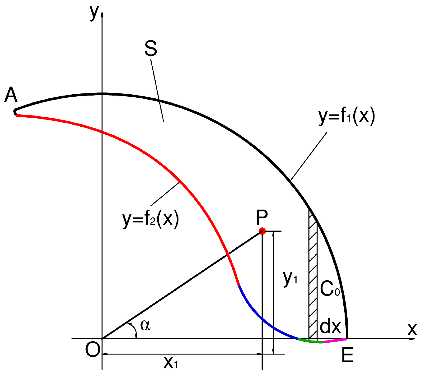
In this section, the shape of helical flute was changed to make the equal pitch equal helix end milling cutter have an eccentricity based on the radial section design in
Section 2. The specific approach is shown in
Figure 5. The coordinates of points A, B, C, D, and E of helical flute curve in
Figure 2 were kept unchanged. Only the curvature radius of arc AB in helical flute ① was changed, so that the overall eccentricity was the same as that of the irregular end milling cutter.
It needs to be explained that the position of the centroid could be controlled by adjusting the curve of the helical flute [
15], so the overall eccentricity of each end milling cutter is the same. The geometric parameters of the four types of end milling cutters, A, B, C, and D, are shown in
Table 1.
3.2. Centroid Distribution
The centroid change of each type of end mill depends on the mass distribution of the bar material removed though the grinding helical flute. Therefore, to study the centroid distribution of the end mill, we only needed to calculate the centroid position of each section of the blade length. The irregular tooth end milling cutters were discretized at equal distances along the axial direction. According to
Table 1 and Equations (9)–(13), the abscissa and ordinate,
and
, of the cross-section centroid of the end milling cutters at any length h can be obtained:
where
,
. The formula for the abscissa and ordinate of the centroid of the equal pitch equal helix end milling cutter becomes:
where
S1 is the area of helical flute ①
S is the area of the other ones.
are the abscissa and ordinate of the centroid after rotating along the helical flute. The eccentricity of each section of the end milling cutter can be expressed as:
According to Equations (15)–(17), the abscissa and ordinate distribution of the end milling cutters can be obtained, as shown in
Figure 6 and
Figure 7.
As can be seen from
Figure 6, the centroid abscissas (from head to neck) of each section of the A-type, C-type, and D-type end milling cutters gradually decreased with a change in height
h. The centroid abscissas of each section of the B-type end milling cutter decreased at first and then increased with a change in height
h. The centroid abscissas of both the A-type and B-type milling cutters were −0.038020 mm in the end section of the cutter head at
h = 0 mm. The centroid abscissa at the
h = 0 mm section of C-type end milling cutter coincided with the origin. The centroid abscissa of
h = 0 mm section of D-type cutter was 0.024342 mm. For the A-type end milling cutter, the centroid coordinate was farthest from the origin in the
h = 15 mm section, which was −0.29070 mm. The boundary section of the B-type end milling cutter decreased and the increase in abscissa was
h = 13.2 mm, and the coordinate was the farthest from the origin, which was −0.057100 mm. For the C-type end milling cutter, the centroid coordinate was farthest from the origin in the
h = 13 mm section, which was −0.22910 mm. For the D-type end milling cutter, the centroid coordinate was farthest from the origin in the
h = 30 mm section, which was −0.067900 mm.
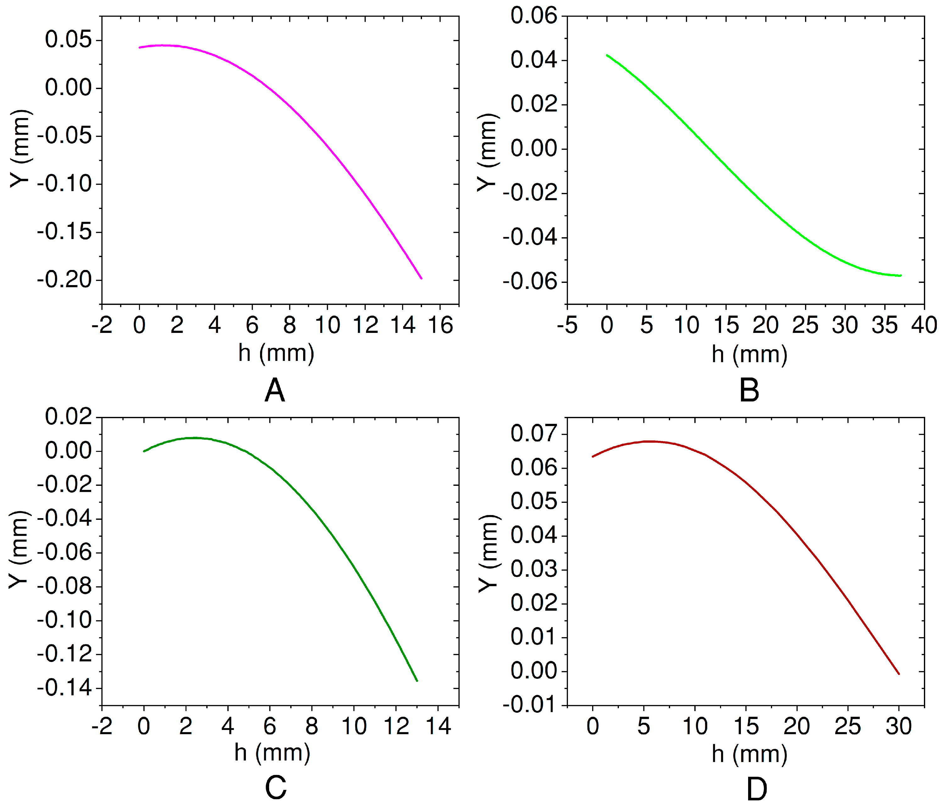
As can be seen from
Figure 7, the centroid ordinates of each section of the A-type, C-type and D-type end milling cutters increased at first and then decreased as the height
h increased. The centroid ordinate of each section of the B-type end milling cutter decreased with the increase in height
h. The ordinate of the centroid in the
h = 0 mm section (end section) of the A-type and B-type end milling cutters were all 0.042450 mm. The ordinate of centroid in the
h = 0 mm section of C-type end milling cutter coincided with the origin of the coordinate. The ordinate of the centroid in the
h = 0 mm section of the D-type end milling cutter was 0.063459 mm. The boundary section between the increase and decrease in the ordinate of the A-type end milling cutter was
h = 1.2 mm and the ordinate was 0.044800 mm. At section
h = 15 mm, the ordinate was farthest from the origin, which was −0.19813 mm. For the B-type end milling cutter, the ordinate was farthest from the origin at the
h = 37 mm section, which was −0.056900 mm. The boundary section between the increase and decrease of the ordinate of the C-type end milling cutter was
h = 2.4 mm and the ordinate was 0.007900 mm. At section
h = 13 mm, the ordinate was farthest from the origin, which was −0.13548 mm. The boundary section between the increase and decrease of the ordinate of the D-type end milling cutter was
h = 6 mm and the ordinate is 0.067900 mm, which was farthest from the origin.
The boundary section between the increase and decrease of the ordinate of the D-type end milling cutter was h = 6 mm and the ordinate was 0.067900 mm, which was farthest from the origin.
The centroid distribution of type A–D end milling cutters are shown in
Figure 8. Red curve e is the eccentricity of each cross section of the end milling cutter and blue curve θ is the eccentric angle of each section.
The distance between the centroid coordinate and the coordinate origin of each section can be calculated according to the calculation formula of eccentricity and the cross-section centroid coordinate of the end milling cutter. It is known that the distance between the centroid position and the coordinate origin of each section of the A-type and C-type end milling cutters increased gradually with an increase in h from the tool head to the tool neck, while the distance between the centroid and the coordinate origin of each section of the B-type and D-type end milling cutters varied a little. The eccentric angle of the centroid position of each section of the A-type end milling cutter gradually changed from −48.151° in the h = 0 mm section to 34.277° in the h = 15 mm section. As h increased from 0 mm to 15 mm, the eccentricity increased gradually from 0.056987 mm to 0.35180 mm. The eccentric angle of the centroid position of each section of the B-type end milling cutter changed from −48.151° in h = 0 mm section to 89.697° in the h = 37 mm section. The eccentricity of each section was about 0.050000 mm, almost unchanged.
For the C-type end milling cutter, the eccentric angle of each section changed gradually from 0° in the h = 0 mm to −17.278° in the h = 0.1 mm section, and then gradually to 30.598° in h = 13 mm section. In the h = 0 mm section, the centroid coincided with the coordinate origin, and in the h = 13 mm section, the eccentricity reached a maximum value of 0.26616 mm. The eccentric angle of the D-type end milling cutter changed from 69.01° in the h = 0 mm section to 87.6° in the h = 5 mm section, then to −88.63° in the h = 6 mm section, and finally to 0.58° in the h = 30 mm section. The eccentricity was about 0.067000 mm.
The centroid positions of each section of the designed type A–D end milling cutters were calculated by using the centroid calculation mathematical model. It was found that although the overall eccentricity of the type A–D end milling cutters were the same, the centroid distributions are different: the centroid position of each section was different, the change trend of the abscissas and ordinates of the centroid ere different, the eccentricity angles of each section were different, the maximum eccentricities were different, and the sections of the maximum eccentricity were different.
4. Dynamic Characteristics Analysis
The dynamic characteristics of the end milling cutter determine the degree of milling vibration to a certain extent. In this section, the dynamic performance of the irregular tooth end milling cutter are studied using modal analysis and harmonic response analysis.
4.1. Principle of Modal Analysis
The free vibration mode can be used to synthesize any motion of a multi-degree-of-freedom structural system. The essence of the analysis is to solve the natural frequency and mode shape of the free vibration of a discrete elastic continuum under the conditions of no damping and no external load with finite degrees of freedom. The modal coordinates of the principal modes of each order of the analytical body are made to replace the physical coordinates, the independent differential equations are decoupled, and the free vibration equations could be obtained. The basic equation of dynamics can be expressed as [
21]:
where
is system quality matrix,
is system stiffness matrix,
is node displacement matrix,
is the second derivative of node displacement with respect to time. Equation (19) can be regarded as the superposition of
n different harmonic vibrations, and its solution is:
where
is modal shape of nth order,
is natural frequency, and
t is time variable. It can be seen from (20) that the degrees of freedom of all vibrating structures move synchronously, and only the amplitude of the analytical body structure changes, but its basic shape does not change. The characteristic equation can be obtained by substituting it into (19):
If there is a non-zero solution, then:
where
λ is the eigenvalue. Assuming that the elastic continuum is discretized into i groups, each group corresponds to an eigenvalue
, and the determinant is 0 at only one set of eigenvalues, then (21) becomes:
where
n is the dimension of the stiffness matrix
,
is the
ith eigenvalue of the characteristic equation,
is the
ith natural frequency corresponding to the eigenvalue,
is the
ith modal shape corresponding to the eigenvalue. The stiffness matrix and the real number matrix are real symmetric matrices, according to the mathematical orthogonality [
29]:
where
is generalized mass, and
generalized stiffness. From the above formula, it can be known that any modal shape cannot be obtained by linear combination of other modes. Each natural frequency corresponds to a mode shape. The higher the order of the mode shape is, the smaller the vibration amplitude is and the smaller the deformation is.
4.2. Modal Simulation Analysis of End Milling Cutter
In this section, the finite element modal analysis method is used to solve the eigenvalues and eigenvectors of the system, and the eigenvalues and eigenvectors obtained are the natural frequencies and vibration modes of the end milling cutter. According to the actual milling speed range of the end milling cutter, the first six natural frequencies and modal shapes of the type A–D end milling cutters are calculated in this section. The finite element model established in
Section 3.1 was imported into finite element software, and the material properties of end milling cutter were set, as shown in
Table 2.
According to the actual clamping situation of milling, the end of end milling cutter handle was set to full constraint. After the analysis types and options were specified, the first six-order natural frequencies of the type A–D end milling cutters were obtained, as shown in
Table 3. The natural frequency is the main factor considering the stability of the milling process. When the external excitation frequency is the same as the natural frequency of the end milling cutter, resonance will occur and vibrations will increase.
From the first six natural frequencies of the solution, it can be found that the difference between the first and second natural frequencies of theA-type and B-type end milling cutters is only 0.1 Hz. The first-order and second-order natural frequencies of the C-type and D-type end milling cutters are equal. For each type of end milling cutter, there is little difference between the third- and fourth-order natural frequencies, while the fifth- and sixth-order natural frequencies varies a lot. The third- and fourth-order natural frequencies of the A-type end milling cutter are near 6746.0 Hz, which are higher than those of the B-type and C-type end milling cutters and lower than the D-type end milling cutter. The fifth natural frequency of A-type end milling cutter is lower than that of the B-type end milling cutter, slightly higher than the C-type end milling cutter, and smaller than the D-type end milling cutter. The sixth natural frequency of the A-type end milling cutter is lower than that of the B-type end milling cutter, similar to the C-type end milling cutter, and slightly lower than the D-type end milling cutter. On the whole, the frequency of each order of the type A–D end milling cutters changes: the first- and second-order frequencies are similar, the third- and fourth-order frequencies are not much different, and the fifth- and sixth-order frequencies are far apart. The frequency values of each order, among each end milling cutter, are roughly the same. The results show that the tool structure has little effect on the natural frequency of different orders. In addition, the range of frequencies that can be used as the basis for harmonic response analysis is shown in the following passage.
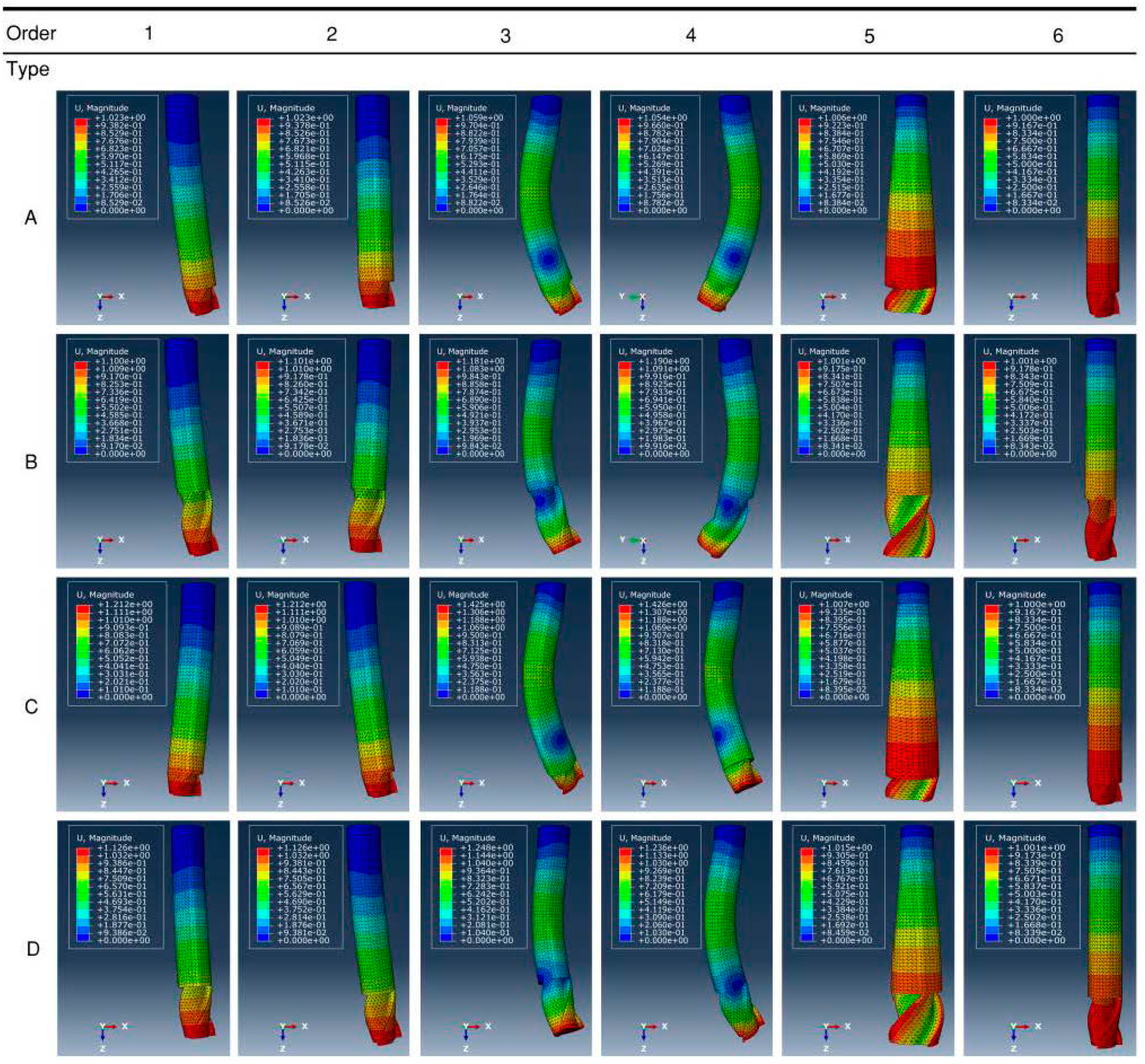
The first six mode shapes of the type A–D end milling cutters are shown in
Figure 9. From the modal diagram, it can be seen that the first and second vibration modes of the type A–D end milling cutters are similar to each other, and they all swing in the XZ plane, but the swing directions are slightly different. The vibration modes of the third-order and fourth-order end milling cutters are all integral torsion. Among them, the torsion direction of the fourth-order of the A-type and B-type end milling cutters are in the YZ plane, and the C-type and D-type are in the XZ plane. The fifth modal of all types of end milling cutters are the vibration deformation in the direction of rotation. The vibration modal is enlarged radially from the handle to the head. The vibration mode of the sixth-order end milling cutter changes evenly in the whole tool, and the deformation is mainly caused by overall expansion. From the vibration mode, there is no bending and torsion. It is known that the vibration modes of the A, B, C and D end milling cutters are similar and the vibration directions are similar.
4.3. Principle of Harmonic Response Analysis
The end milling cutter works periodically with the rotation of the spindle, and the milling force also changes periodically. The modal analysis method alone cannot well reflect the response characteristics of the end milling cutter caused by dynamic excitation in the actual milling process. In this section, the harmonic response analysis method is used to simulate the response characteristics caused by dynamic excitation in the end milling process, so as to further analyze the dynamic characteristics of end milling cutters.
Harmonic response analysis is used to determine the steady-state response of structures excited by sinusoidal loads with known frequencies and amplitudes. The response displacement of structures under different frequency loads can be obtained by harmonic response calculation [
22]. Considering the actual milling situation, the harmonic response analysis of this section is based on steady-state forced vibration, and the system is subjected to continuous periodic loads. Assuming that the analyzed end milling cutter is an elastic material, the small deformation in the analysis process is regarded as a linear process, and external excitation load F varies sinusoidally according to the given frequency; the general equation of motion is as follows:
In the harmonic response analysis, both the force
and the displacement
are simple harmonic, and
is the frequency, so the displacement and frequency can be expressed as:
where
Umax is the amplitude of displacement,
Fmax is the amplitude of force,
ϕ is the phase of angular displacement,
ω is the circumferential frequency. Substitute (29) into (28) to obtain:
4.4. Harmonic Response Analysis
The harmonic response analysis is also called frequency sweep analysis. Through applying the load boundary condition to the opposite milling cutter, the amplitude of the end milling cutter in different natural frequency range is obtained. Two kinds of load boundary conditions are mainly used in frequency sweep analysis: (a) concentrated force is applied at the tool tip and (b) a linear load is applied at the cutting edge. Considering the actual working conditions of the end milling cutter, with reference to previous studies [
30], in this paper, a single concentrated 2
n force was applied at the tip of the irregular tooth end milling cutter to replace the actual load. From the results of the
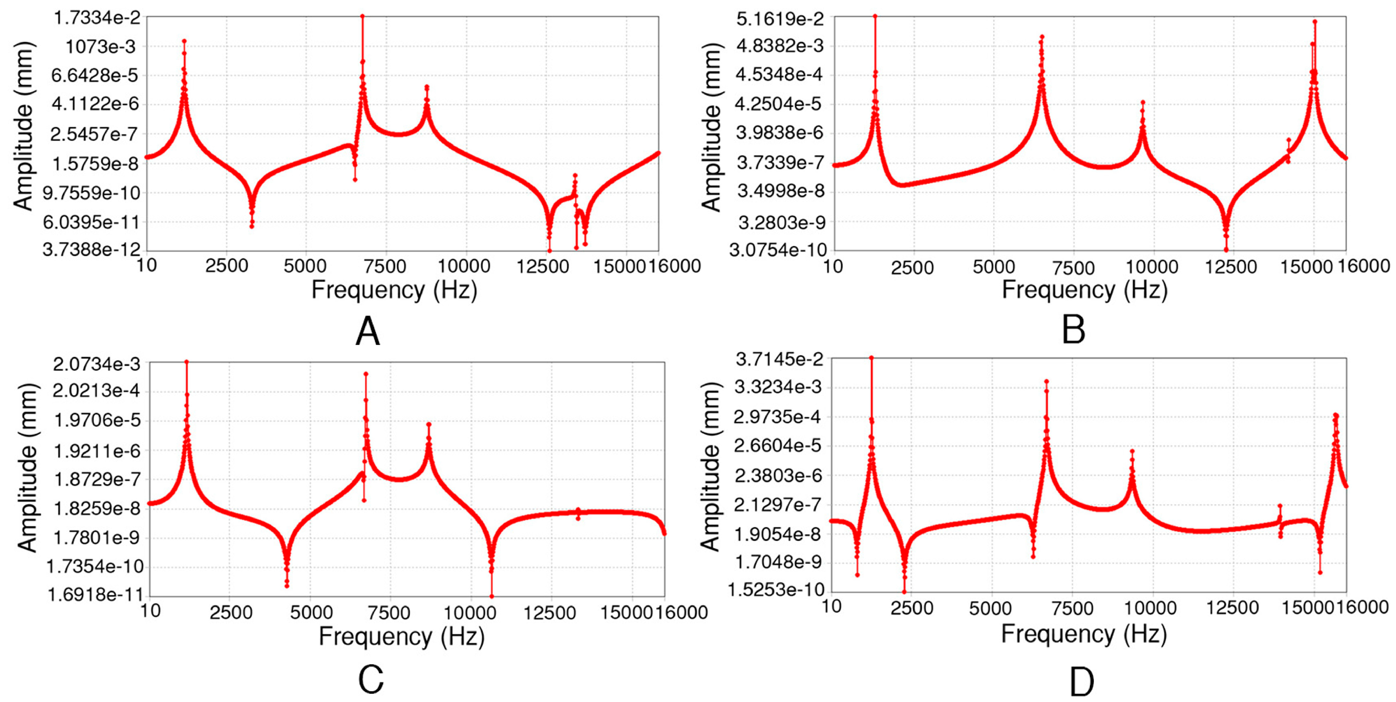
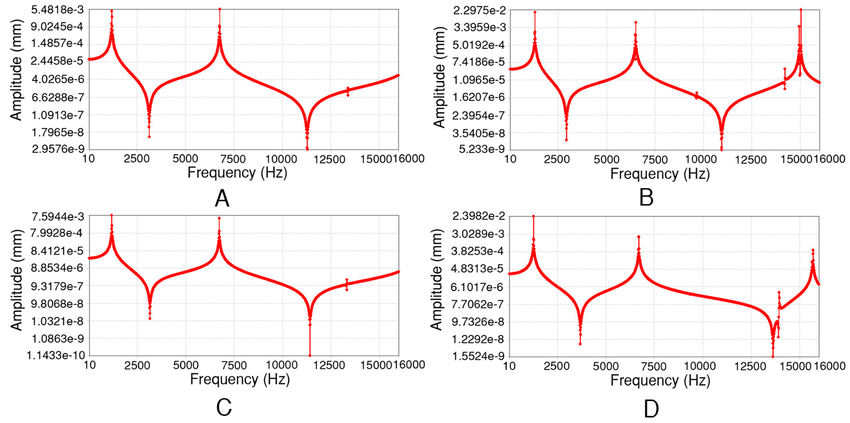
Section 4.2 modal analysis, it is known that the frequency range of 1 to 6 modal orders is 1170.4 Hz–14,192 Hz. In order to ensure the accuracy of analysis, the analysis frequency range 0–16,000 Hz and frequency interval 10 Hz were set. The amplitude response curves of the type A–D end milling cutters in the directions of
x,
y, and
z are shown in
Figure 10,
Figure 11 and
Figure 12.
From the amplitude response curve, it can be seen that the maximum amplitude response of the end milling cutter appears near the first and second natural frequencies. According to the modal analysis results in the previous section, the frequency of the external excitation load range is 1000 Hz–1500 Hz, and the total displacement harmonic response curves of A, B, C and D end milling cutters are pertinently calculated, as shown in
Figure 13.
It can be seen from the figure that when the milling frequency is lower than 1100 Hz and higher than 1300 Hz, the amplitude of the A–D type end milling cutters tends to be infinitesimal. When the frequency range is from 1100 Hz to 1300 Hz, the A-type end milling cutter resonance frequency band is from 1160 Hz to 1200 Hz, the resonance frequency band of the B-type end milling cutter is higher than that of the A-type end milling cutter in 1270 Hz–1310 Hz, the resonance frequency band of the C-type end milling cutter is similar to that of the A-type end milling cutter in 1150 Hz–1190 Hz, and the resonance frequency band of the D-type end milling cutter is in 1240 Hz–1280 Hz. When the frequencies of the type A–D end milling cutters are at 1180 Hz, 1290 Hz, 1170 Hz, 1260 Hz, the displacement of each type of end milling cutter reaches a peak at 0.043800 mm, 0.17930 mm, 0.072100 mm, and 0.22670 mm, respectively. The response displacement of each type of the end milling cutters under the same dynamic excitation: A < C < B < D. It can be known from the results that there is little difference in the frequency corresponding to the maximum response displacement of end milling cutters with different structures. Moreover, the range of their resonance frequency bands are similar. Thus, the dynamic performance of the type A end milling cutter is the best.
Combined with the finite element modal analysis, the first six natural frequencies of the type A, B, C and D end milling cutters have little difference among the same orders, and the modal shapes are as follows: first- and second-order integral swing, third- and fourth-order integral torsion, fifth-order radial expansion and sixth-order uniform expansion. It is known that the vibration modes of the same order of the A–D end milling cutters are the same. From the analysis of the amplitude response curve of the end milling cutter, we can know the resonance frequency band and the maximum response displacement of each type of end milling cutter. According to Equations (1) and (2), combined with the results of the finite element analysis, when the quality of the end milling cutter is constant, the unbalance of all types of end milling cutters with the same overall eccentricity is fixed. When the milling speed is determined, the dynamic balance accuracy grade is determined, that is, for the end milling cutter with a certain dynamic balance accuracy grade, the dynamic performance of the A-type end milling cutter is the best.
5. Conclusions
In this paper, the centroids of each radial section of an end milling cutter with the same eccentricity and different structures are calculated and analyzed, and the dynamic characteristics of the cutters are studied using the finite element method. The main conclusions are as follows.
(1) A new general mathematical model for calculating the centroid of the radial section of an end milling cutter is established, and the proposed mathematical model can be widely used other kinds of end milling cutters. The centroid of each section of the designed end milling cutter is calculated. According to the calculations, it is found that the centroid distribution of the type A–D end milling cutters with the same overall eccentricity are different: the position of the centroid of each section are different, the change trend of the abscissas and ordinates of the centroid are different, the eccentricity angles of the centroid position in each radial section are different, and the maximum eccentricities are different, which are 0.35180 mm, 0.050000 mm, 0.26616 mm, 0.067000 mm, respectively. In addition, the sections of the maximum eccentricity are different. For the A-type end milling cutter it is at the h = 15 mm section, for the C-type it is at the h = 13 mm section, and the eccentricity of each section of the B-type and D-type end milling cutters do not change much.
(2) Combined with finite element modal analysis, all types of end milling cutters with the same eccentricity have the same modal shapes and similar natural frequencies in the same orders. Through finite element harmonic response analysis, the resonance frequency bands of various types of end milling cutters are obtained. Under the same dynamic excitation, each type of end milling cutter responds to displacement: A = 0.043800 mm < C = 0.072100 mm < B = 0.17930 mm < D = 0.22670 mm.
(3) Through investigation, it is found that the dynamic characteristics of the end milling cutter with the same eccentricity but different structure are different. The dynamic performance of each type of end milling cutter with the same overall eccentricity and the same level of dynamic balance accuracy: the A-type end milling cutter is the best, followed by the C-type end milling cutter, and the B-type end milling cutter is better than the D-type end milling cutter. This shows that the centroid distribution may have an effect on the dynamic characteristics of the milling cutter. Without changing the overall eccentricity, it provides a new idea for the structural design with the goal of improving the dynamic characteristics of the end milling cutter, and provides a theoretical basis and reference for the high precision design of the end milling cutter.


