1. Introduction
Multiphase electric machines have been frequently discussed in recent years by professionals worldwide, where the term “multiphase” refers to machines with more than three phases. The results of various authors have described an improvement in efficiency, the harmonic spectrum of MMF, a lower phase current and torque ripple, and, most significantly, parameters related to the system’s fault tolerance and redundancy [
1,
2,
3,
4,
5]. Multiphase machines are used in high-power applications for a reduction in phase current stress, e.g., huge cargo ships, mills, and wind power plants [
6,
7]. All these advantages are, of course, dependent on many variables, especially based on the particular design of a machine. Various numbers of phases are used for applications involving 5-, 6-, 9-, 12-, and 15-phase machines. The most preferred ones are six-phase machines. They are simple to control, are easy to use, and can be driven by two pairs of well-known three-phase converters. Today, six-phase electrical machines dominate in the field of critical applications, where a higher level of redundancy, safety, and fault-tolerant behavior is required [
8,
9,
10].
Permanent−magnet synchronous machines (PMSMs), in general, are used in a large set of applications, and the automotive industry is no exception. PMSMs can be found in window lifts, water pumps, seat and mirror positioning elements, fans, and other auxiliary drives; the most well-known PMSM is the automotive body segment. The body segment represents the lower corner case of PMSM use. Other applications such as electrical starters, brakes, e-turbo, power steering, and main traction drive units represent middle and upper corner cases of PMSM use. This kind of electrical machine is often controlled by a well-known field-oriented control.
Field-oriented control can be accomplished using a six-phase PMSM via several methods. In various applications and research works, two main approaches can be recognized according to the number of current controllers used for torque− and flux−producing components of a whole machine.
One approach is where the six-phase machine is reflected as one entity, where the torque/flux control works in one orthogonal system. In [
11], a vector space decomposition (VSD) method was introduced as a control of torque/flux components in one orthogonal subspace, with current harmonics elimination. Modulation techniques for this control topology were discussed in [
12], while realization of the VSD method with control in a stationary reference frame was proposed in [
13]. A method with only two current sensors for the field-oriented control of a six-phase machine was shown in [
14]. In [
5], the post-fault behavior was investigated for a one-phase fault in a six-phase induction machine. The same transformations as for healthy conditions were used, whereby
z1z2 reference currents in the VSD method were recalculated according to coefficients on the basis of the criteria of maximal torque or minimal losses. An investigation of VSD harmonics control was presented in [
15], where asymmetries were created through the addition of external passive components. In [
16], general VSD transformations were proposed. The algorithm works for multiphase machines with an optional number of phases.
Another approach considers the six-phase machine as two three-phase machines in parallel, and the control is divided into two orthogonal systems, one for each set. In [
17], such an approach was used, where mutual coupling between two sets of three-phase windings was investigated. A decoupling for this phenomenon was proposed in [
18]. A sensorless technique with separated three-phase winding control was shown in [
19]. In [
20,
21,
22,
23], a method was presented for multiphase machines with
n × 3-phase windings (
n = 2, 3, 4, …). Both techniques have been realized in the past three decades by several authors with various high-level additional algorithms for drive quality improvement.
A method involving two individual current controllers, without a harmonics elimination technique, was compared to the VSD method with harmonics elimination in [
24]. The proposed results showed the same harmonics behavior of both techniques.
This paper demonstrates the inability to achieve natural harmonics reduction when using the method involving two individual current controllers, especially with reduced load. Automotive market target applications such as steering control or main traction drive do not operate at the rated power level all the time. A working cycle of these applications includes operation below the rated power, where the pure two-controller method will not fulfill the best qualitative parameters of the drive, since phase current harmonics lead to additional losses. This paper summarizes the characteristics, advantages, and disadvantages of the abovementioned methods through a comparison, mainly from the software control application point of view. In
Section 2 and
Section 3, the control methods are introduced. In
Section 4, further details, drawbacks, and benefits are discussed. Lastly, the pros and cons are summarized in a discussion.
Experimental verification is demonstrated in the setup depicted in
Figure 1a, whereas the phase configuration of the six-phase PMSM is sketched in
Figure 1b. Multiple unconnected research articles have preferred six-phase machines with a 30° shift between a star-connected winding with unconnected neutral points as the most beneficial option. The airgap space harmonic content is significantly reduced, as well as the ripple component, in terms of torque and speed, due to the 30° shift winding configuration [
1,
2]. This configuration of the six-phase machine with a mechanical shift between three-phase sets of windings different from 0° or 60° is often called an asymmetrical six-phase machine. In addition, the machine used in this experiment has a 30° shift between both sets of star-connected three-phase windings, with a so-called dual-star configuration, which means that each three-phase star has a separate neutral point. If these points are joined together, the whole machine has one common neutral point for all six phases, which is called a single-star configuration. The machine was supplied by two standard three-phase converters, with one common DC bus. Both converters were controlled by one microprocessor
MPC5643L (NXP). Currents were sensed using shunt resistors, and a resolver was used as a speed sensor.
2. Control in Two Orthogonal Systems
For a better overview, the abbreviation “2 d-q” is established in this paper as two orthogonal systems. This approach is also known as dual, modular, or multiple three-phase control of
n × 3-phase machines (
n = 2, 3, 4, …), as presented in [
17,
18,
19,
20,
21,
22,
23]. As mentioned, three-phase field-oriented control is well known among engineers of electric drives, even for the control of two separated three-phase PMSMs by one microprocessor. Such an approach was adopted for the control of the six-phase machine, where a control structure was adapted to a common speed loop, as depicted in
Figure 2.
Two identical control structures were run in parallel, one for each three-phase system, where, in the second system, the transformation angle was shifted by −30° in direct and inverse Park transformations. Similarly, an n × 3-phase system can be controlled using functions intended for the control of conventional three-phase machines, limited by MCU power and a peripheral set. The point of connection for two parallel systems is in the speed loop, because the machine still contains just one shaft and produces one mechanical torque. In the 2 d-q control, all functions involved in the control of three-phase machines can be used, and the shape of the Clarke transformations or modulation function can remain unchanged.
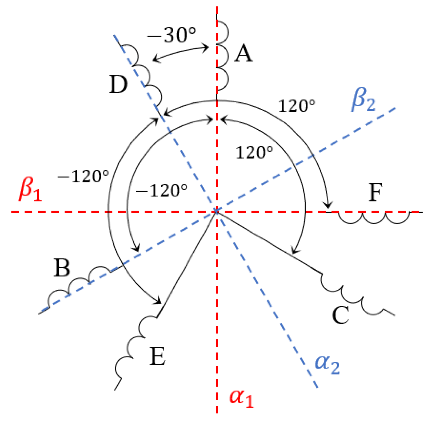
As a result of the 2 d-q control approach, two aligned sets of d-q currents/voltages in the rotor reference frame can be observed as two current loops run in parallel, controlled by separated, individual current controllers. Furthermore, two sets of α−β orthogonal values in the stator reference frame can be recognized, where α1 is aligned to phase
A, and β1 leads α1 by 90°, whereas the second orthogonal set α2, β2 is shifted by −30° from the first, as shown in
Figure 3.
3. Control in a One Orthogonal System
Furthermore, for a better overview, the abbreviation “1 d-q” is established in this paper as one orthogonal system. This approach is also known as the two-controller method, where various modulation techniques might be applied, as shown in
Section 4. With an inclusion of higher harmonic control, it is known as the vector space decomposition (
VSD) method [
5,
11,
12,
13,
14,
15,
16,
25,
26,
27,
28,
29,
30,
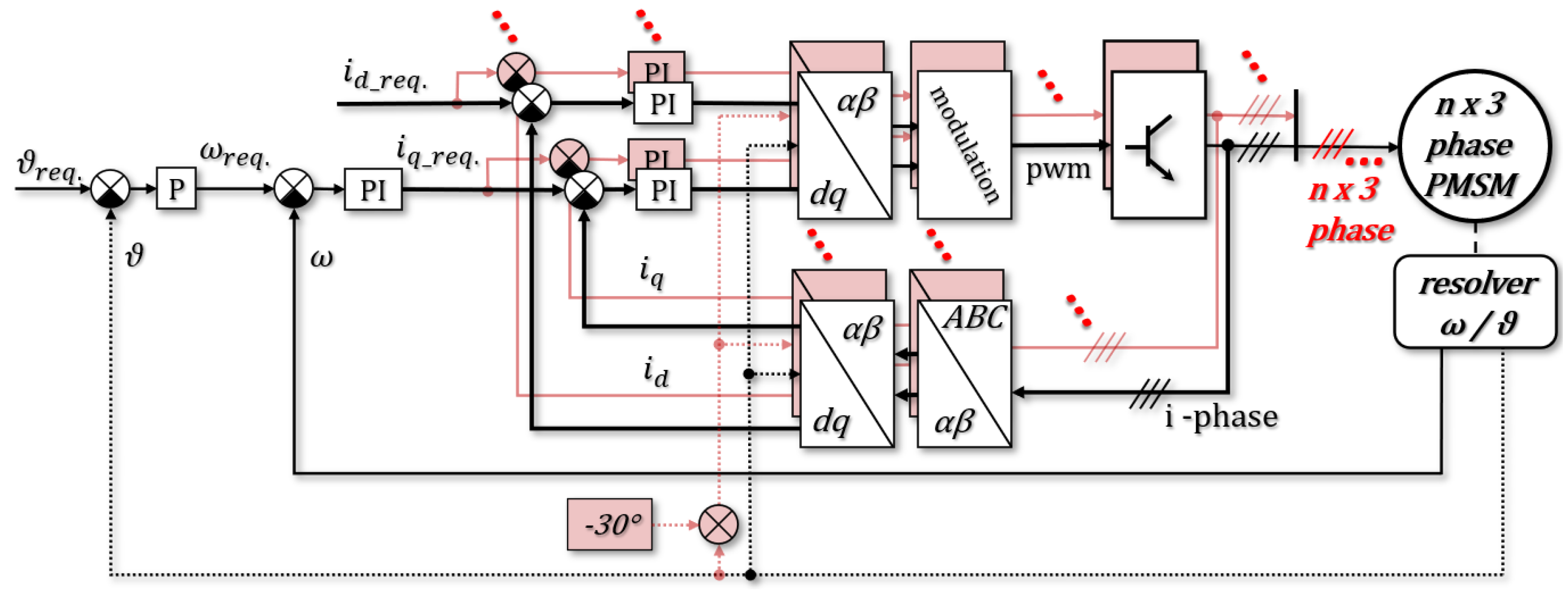
31]. An approach of the 1 d-q field-oriented control, specified to a six-phase system, is shown in
Figure 4. The whole control structure is shaped similarly to a standard one for three-phase machine control. Parallel operation of current loops is not required, since the structure contains just one set of flux/torque−producing components for the whole six-phase system. On the other hand, transition sections between the six-phases and one orthogonal system in both direct and inverse directions depend on the functions specified for a number of phases in a controlled machine.
Park transformations between an orthogonal rotor reference frame d-q and a stationary α−β reference frame are the same as those used in the standard field-oriented control of the three-phase PMSM. In this case, just the one orthogonal α−β system can be recognized, where α is aligned to phase
A, and β leads α by 90°, as depicted in
Figure 5. Moreover, just one set of d-q stator currents/voltages can be observed.
Clark transformations in inverse and direct directions were reconstructed under the rule of the generalized Park transformation with a zero position reference frame (
Figure 5). This approach can be used for any number of phases according to the following known parameters: angles between phases, number of phases, and an arbitrary parameter taken as the reference frame position of the orthogonal α−β system. With the use of the six-phase machine where at least one three-phase star is a convectional, balanced, symmetrical system with 120° between phases, an advantage can be taken into an account. This first system can be calculated using the standard three-phase Clark transformations, and the other phases can be added into transformation equations according to their angles to the reference frame.
The transformation between the
n-phase and the orthogonal system is always recalculated by coefficients of a proportion. For example, with
kd =
kq = 2/3 for three-phase machines, the transformed system is power noninvariant (an amplitude invariant), and the same applies to the 2 d-q system, as described in the previous section. Transformations to the 1 d-q system with
kd =
kq = 2/3 will lead to a system behavior with double gain, thus neither the power nor the amplitude is invariant. With the requirements of amplitude−invariant behavior, the coefficients of proportion
kd =
kq = 2/6 were used [
32]. The proposed transformation can be used for a variable angle (
ϑshift) between two symmetrical three-phase systems. For the machine examined in this paper,
ϑshift = −30°.
4. System Realization and Comparison
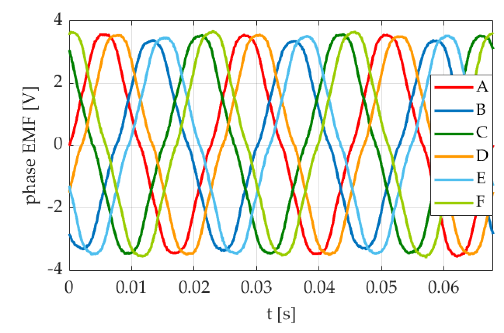
The aim of standard electric motor control is to supply a machine with phase voltages in the same order, shift, and shape as the EMF of the supplied machine. Transformations have a large impact on this requirement in field-oriented control. Their correctness can be verified by a comparison of the phase current order, shift, and shape in a motor mode with the phase EMF sensed using an oscilloscope in generator mode, over the same direction of a shaft rotation (
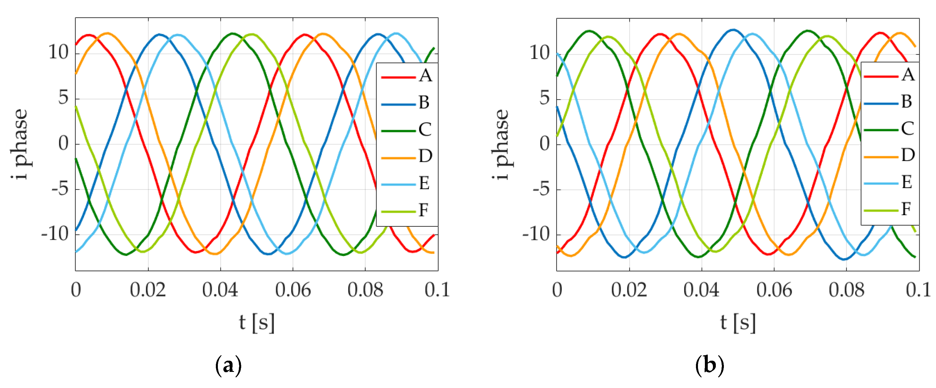
Figure 6). For a correct phase identification, the record of the EMF is also required. The same applies to PWM references, except for the shape, which is dependent on the modulation technique used and does not always follow the shape of the EMF. In most real applications controlled by a microprocessor, PWM references are inputs for a timer compare unit, which generates control signals for power transistors. PWM references can be accomplished using many modulation techniques, a few of which are discussed in the next section as a review of the state of the art, with emphasis on the six-phase design implementation. The measured currents of the six-phase PMSM investigated in this experiment are shown in
Figure 7 and
Figure 8.
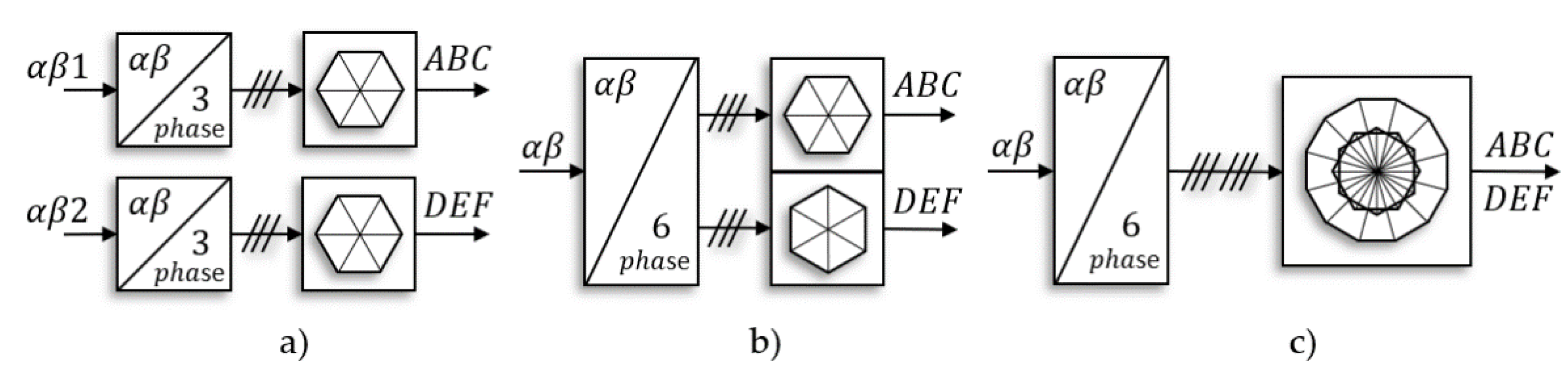
Modulation of the 1 d-q control can be accomplished, for example, using a 12-sector diagram [
11,
12,
33] (
Figure 9c), with separated 2 × 6 sector diagrams [
12,
28] (
Figure 9b) or even a 24-sector diagram [
33]. The vector space decomposition (VSD) method is often used in the 1 d-q control approach, which was introduced in probably the most referenced article by worldwide authors in the field of multiphase machines [
11] with a stationary reference frame. This technique is focused on the harmonic spectra of stator currents, which might arise in a six-phase machine because of asymmetries, and their elimination can be achieved using various approaches, where the most beneficial for the impact of any kind of asymmetry (inverter, motor) is a VSD transformation to both a synchronous and an anti-synchronous reference frame [
15]. VSD control of the six-phase machine is based on a transformation of phase values to an orthogonal
z1z2 frame (
xy frame according to some authors [
15]) through fifth harmonic arguments of goniometric functions. The transformation leads to a separation of currents i
z1, i
z2 from fundamental component. This separated subspace represents unwanted higher-harmonic currents of the fifth order, which are not torque/flux−producing components in a six-phase machine with the configuration shown in
Figure 1b, but which cause additional copper losses. For this reason, i
z1, i
z2 are regulated to zero, as explained in [
11,
15].
As a matter of machine design, asymmetries do not have to be present with values demonstrated in [
11] for every machine or work condition. The phase current shows that the impact of higher harmonics is minor in conditions near to a nominal load, as shown in
Figure 7, while they are quite significant for a lower level of stator currents, as shown in
Figure 8. These harmonics might be caused by various system asymmetries, including a dead-time effect.
In the case of 2 d-q control, it is standard to use the well-known six-sector modulation for the control of three-phase machines, with separately controlled inputs (
Figure 9a). To avoid the impact of controlled system asymmetries, quite large decoupling algorithms are often used [
34]. Some of the decoupling effects might be achieved via appropriate transformations, where the control structure starts to follow the VSD approach, since the required currents for the second orthogonal d-q system have ratings of zero [
35]. The VSD approach was used also for separated three-phase control structures in [
36].
A so-called double zero-sequence injection, which means a third harmonic signal injected into every three-phase system, can be utilized for better DC bus voltage use, as is known from the control of three-phase machines; this is also reusable in
n × 3-phase machines with separated neutral points for every symmetrical three-phase system [
12,
28]. In the case of a six-phase machine, that is an option for a dual-star configuration.
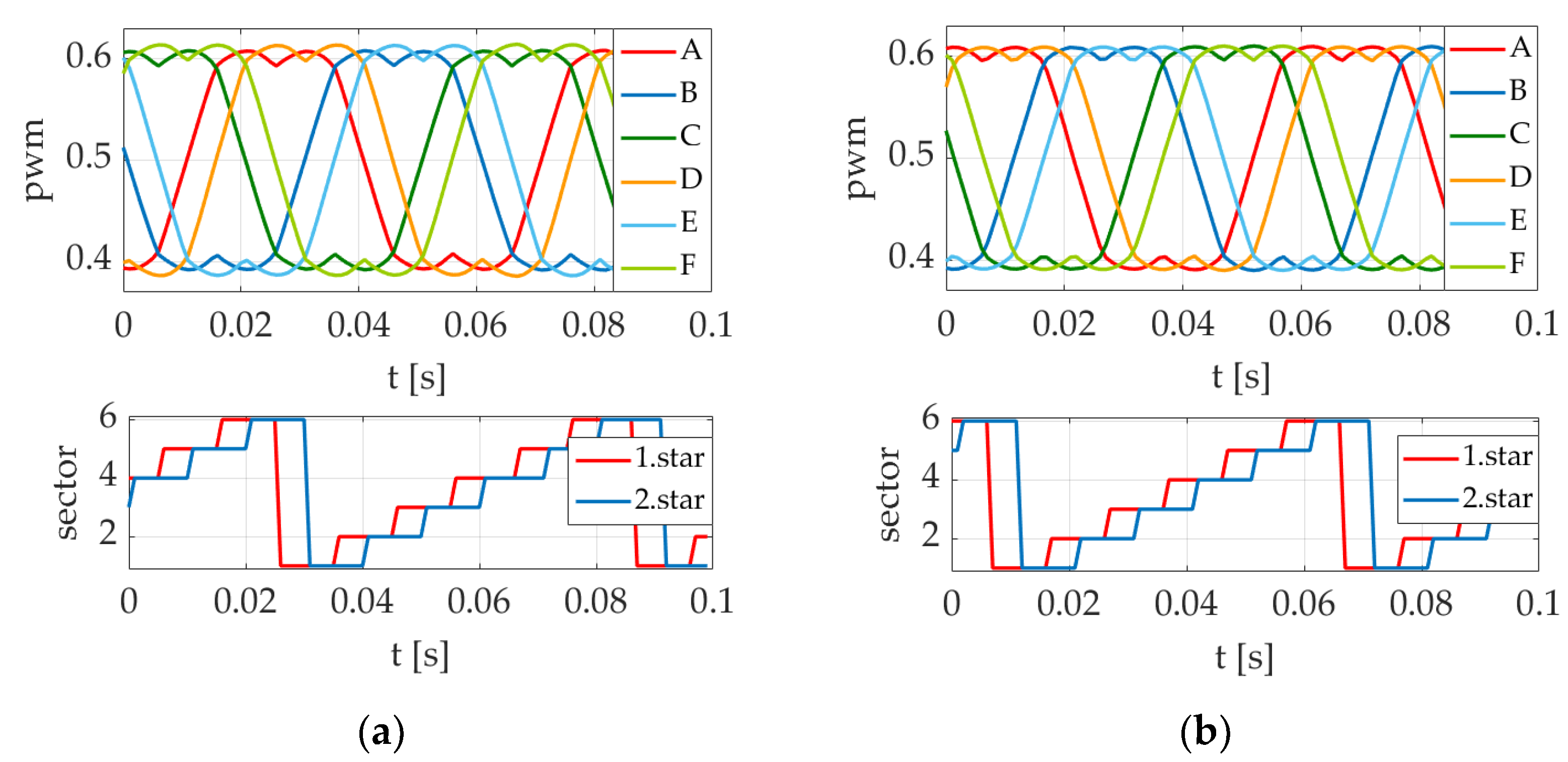
The modulation techniques shown in
Figure 9a for 2 d-q control and
Figure 9b for 1 d-q control were realized, using the double zero-sequence injection in both cases, as depicted in
Figure 10. The steady-state current responses of these techniques are shown in
Figure 7 and
Figure 8.
Another issue in multiphase systems is current sharing. As shown in
Figure 8, if hardware asymmetries are present in the
n × 3-phase electric drive (
n = 2, 3, 4,
…), then, for a better current/power sharing, between three-phase sets of windings, 2 d-q control or
n d-q control is more convenient. This is because individual RL circuits, which represent three-phase windings, are controlled separately (dual-star configuration is considered). This behavior is almost negligible around a nominal load, as shown in
Figure 7, but it becomes quite crucial with reduced load, as shown in
Figure 8. It can be seen from
Figure 10 that to keep amplitudes of phase currents at the same level, PWM references, as a result of required voltages, have various amplitudes for the first and the second three-phase systems when applying 2 d-q control. On the other hand, for 1 d-q control, the current sharing problem may be effectively handled when using the VSD method, even when it is designed by default for higher-harmonics elimination [
11,
15].
The speed and position loops were adjusted using a pole-placement method [
37], where the zero in the transfer function of the speed loop caused by the speed PI controller, was canceled by a first-order filter. Coefficients
kd =
kq = 2/6 were considered for the 1 d-q control system as explained in
Section 3, which led to the same machine parameters transformed in the d-q system for both 2 d-q and 1 d-q control, since the 1 d-q system also became amplitude-invariant. The machine parameters are shown in
Table 1. Measured data were captured using the run-time
FreeMaster tool (
NXP), imported into
Matlab, and compared to a simulation based on a mathematical model [
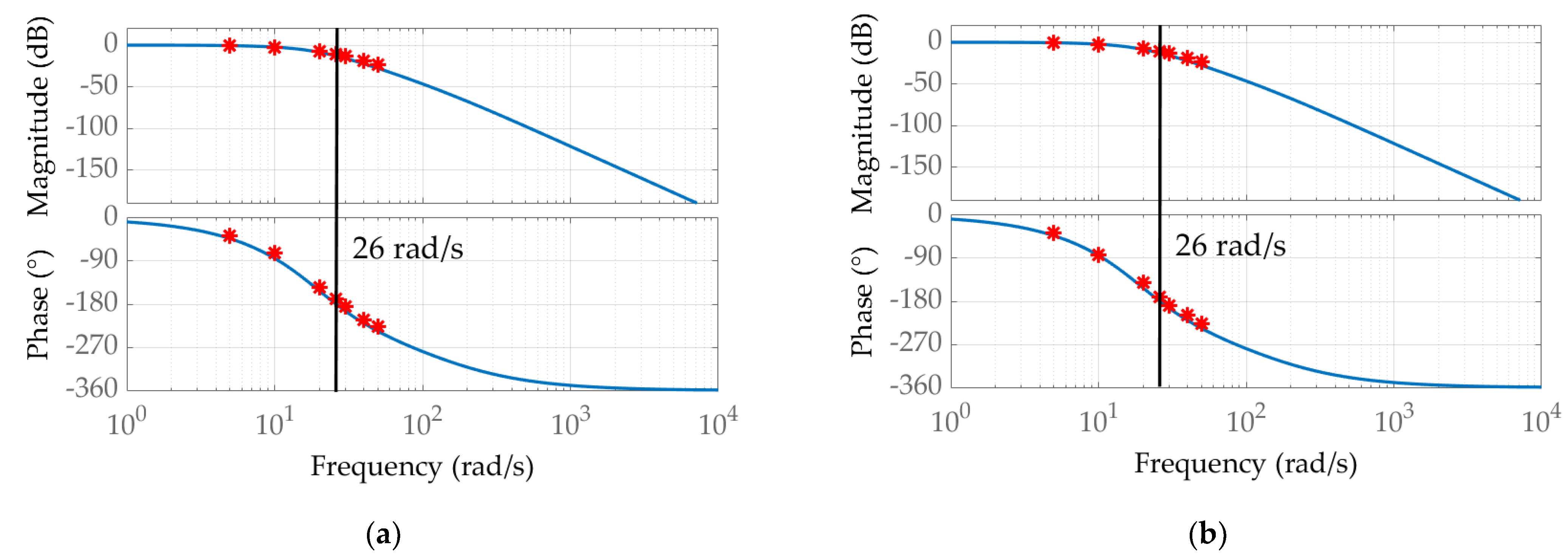
37]. Frequency analysis was executed for every control loop to verify the behavior of the system in dynamic states.
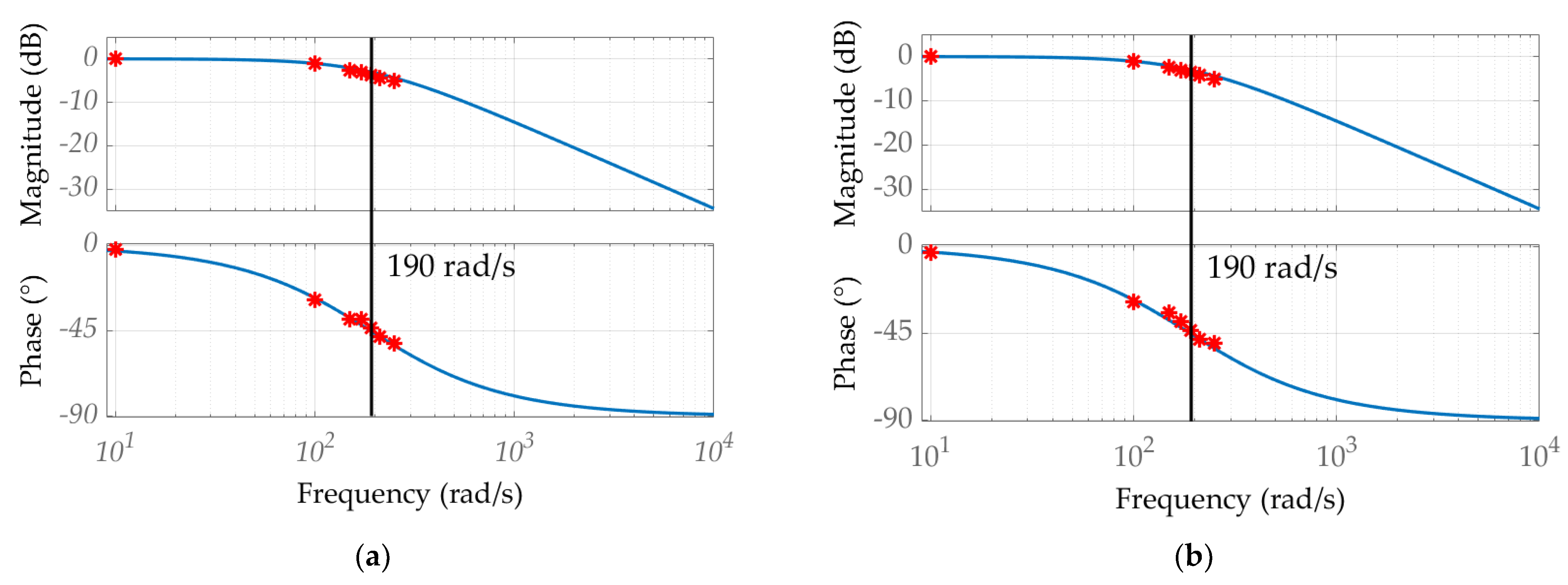
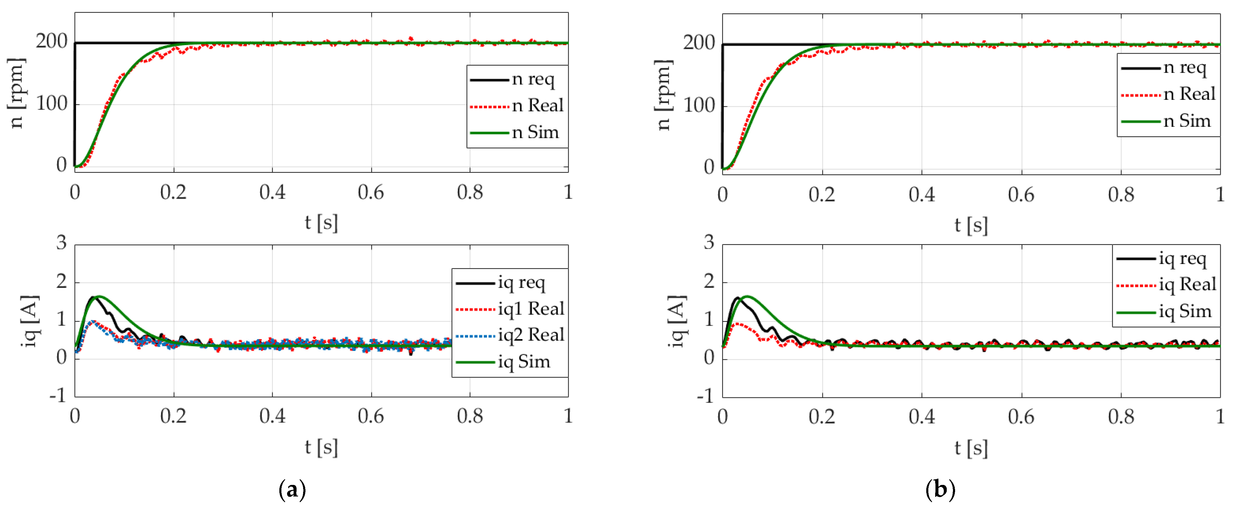
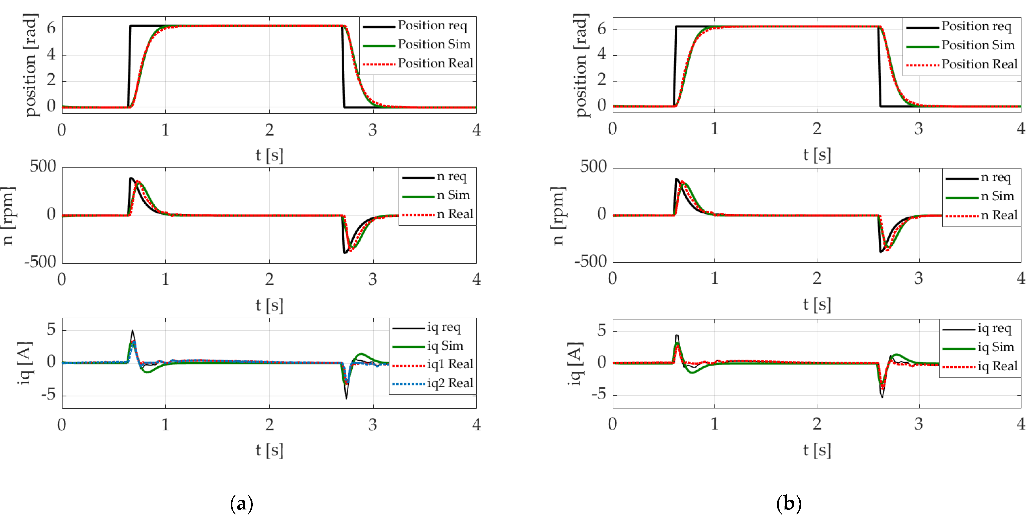
The results are demonstrated as a comparison of the two field-oriented control approaches for six-phase electrical machines discussed in this paper. The measurements in
Figure 11 and
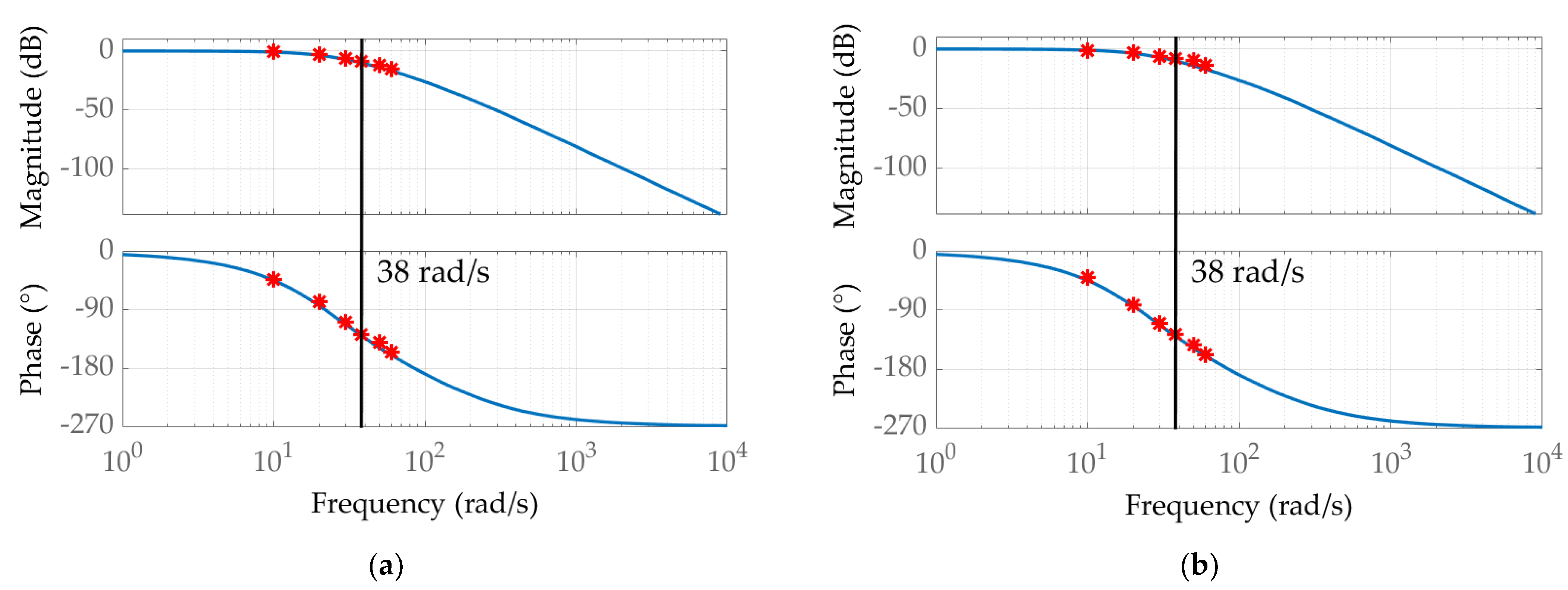
Figure 12 were performed in a fixed rotor state. This approach allowed us to neglect the negative effect of back-EMF voltage since, in the current loop, back-EMF is an error value. The speed loop behavior is presented in
Figure 13,
Figure 14 and
Figure 15, while the position loop results are shown in
Figure 16 and
Figure 17. Frequency analysis was conducted by applying the required sinusoidal values with frequencies corresponding to red asterisks (*) depicted in
Figure 12,
Figure 14 and
Figure 17.
4.1. Current Loop
The current loop was adjusted using the inverse dynamic method on the basis of the PI controller integrational time constant and the time constant of the motor electrical part being equal (in the 2 d-q system, each current loop was tuned separately).
4.2. Speed Loop
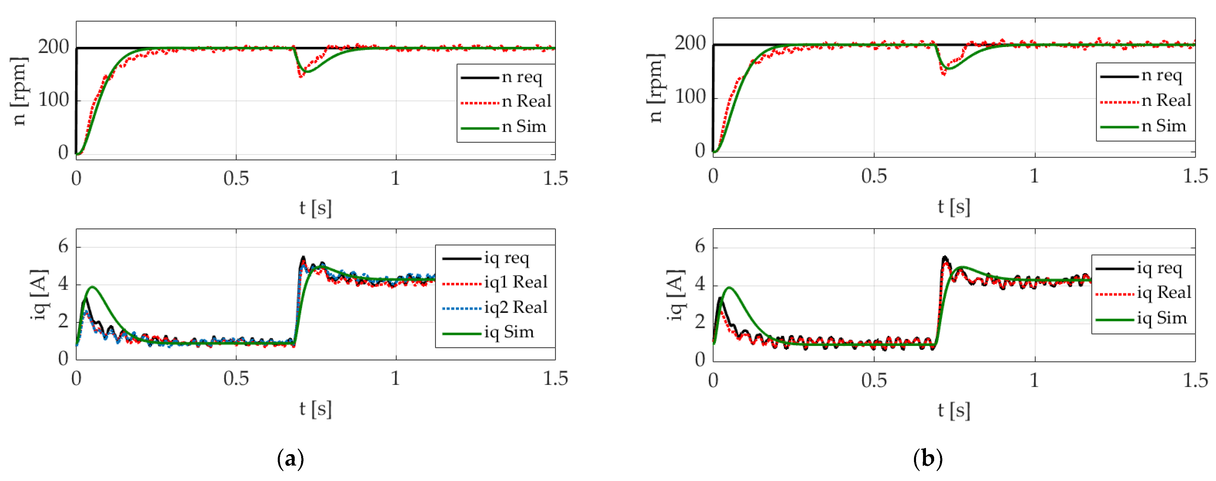
Losses in no-load conditions were embedded into the simulation using an initial torque load value of 0.07 Nm. Experiments were fulfilled with reduced power due to hardware limitations.
A speed control test with load (
Figure 15), was realized via coupling to a three-phase permanent magnet synchronous machine. As the moment of inertia and friction of the load would affect the test throughout the process, they were added as parameters of the loaded machine for controller adjustment, as well as to the simulations. At time 0.7 s, the setup was loaded with an electronic load connected to a winding of the three-phase PMSM load. The measured results were significantly disturbed by a cogging torque of the three-phase PMSM used as a load. Nevertheless, speed control was functional for both 2 d-q and 1 d-q control, without any significant differences.
A dynamic model never perfectly follows a real system. Errors are caused by the measurement accuracy during parameters investigation. The following parameters can be affected by measurement accuracy: resistance and inductance of stator winding, inertia, voltage, and torque constant. These errors also affect the PI parameters. Using a PI gains calculation methods, we could observe a slightly different behavior in the dynamic states of the step response. The transient behavior was also affected by the inverter’s nonlinearities (dead-time, voltage drop over semiconductors, etc.). Other aspects which influence the transient behavior are core saturation, parameters changes due to temperature, the skin effect, and other parasitic effects. These influences were not included in the PMSM d-q dynamic models [
37] when used for PI gains calculation and simulation results.
4.3. Position Loop
Experiments and simulations (
Figure 16 and
Figure 17) were proposed without any load on the shaft. Both control techniques were found to be useful for all levels of cascade control (current−speed−position) constructed as field-oriented control. The stator electrical values transformed to the synchronous rotational orthogonal reference frame, e.g., stator currents, indicated the same behavior for both control approaches; however, their real phase values varied, as shown in
Figure 8, especially with reduced load.
5. Discussion
Two approaches of field-oriented control for a six-phase PMSM were segregated according to the number of current controllers for flux- and torque-producing components. An overview of voltage modulation techniques was presented for both cases, where double zero-sequence modulation was realized. To ensure a transparent and meaningful comparison of these two approaches and to highlight their real differences and drawbacks in the examined six-phase PMSM, control structures were demonstrated using a basic shape, without additional algorithms for drive quality improvement.
Because two loops of a control algorithm were run in parallel for control in two orthogonal systems (2 d-q), as shown in
Figure 2, the execution time of the application might be longer than in one orthogonal system (1 d-q), shown in
Figure 4. Such an application requires a more powerful MCU, which would lead to a higher price of the control unit or a longer sample time, thus leading to inaccuracies. This problem becomes more significant in
n d-q control, for 9-, 12-, and 15-phase machines. The 1 d-q control technique requires a shorter computation time and brings the advantage of a standard field-oriented control system, with only one set of torque/flux-producing components. On the other hand, the 2 d-q technique allows using a standard, well-known transformation for the control of three-phase machines. Requirements for the execution time of a control algorithm would of course vary when utilizing advanced algorithms, such as VSD or various decoupling methods.
The 2 d-q technique is beneficial for natural current sharing between two three-phase windings across all load conditions (
Figure 8). Since each three-phase winding is controlled separately, various decoupling methods between them can be managed directly in the d-q control system. Nevertheless, the influence of the phase current higher-harmonic spectra over the whole-load conditions will not be cancelled in 2 d-q, neither 1 d-q control without additional algorithms. To control harmonics and consequently decrease losses, the VSD method can be utilized, with a shorter execution time for 1 d-q control, whereas the current sharing problem can be solved using the VSD method too.
Both control approaches are able to achieve the same results in terms of current in the synchronous reference frame, speed, and position, as shown in
Figure 11,
Figure 12,
Figure 13,
Figure 14,
Figure 15,
Figure 16 and
Figure 17. This applies to standard operation in both steady and dynamic states. However, the two approaches do not behave similarly in terms of phase current, as shown in
Figure 8.
In addition, the proposed results show the correctness of the mathematical models and transfer functions for both approaches, previously presented by the author of this paper in [
37]. The simulations of dynamic models are displayed in
Figure 11,
Figure 13,
Figure 15 and
Figure 16 as green plots and in
Figure 12,
Figure 14 and
Figure 17 as blue plots, where red dots represent measured data.
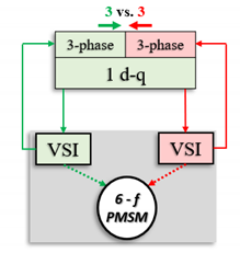
As previously mentioned and highlighted, a strong reason for the application of multiphase machines is redundancy, not only machine redundancy, but also parallelization of the whole system, because of an increase in the safety attribute. For this reason, the 2 d-q control technique seems to be more convenient. However, it becomes a software architecture question, whereby a drive system with 1 d-q control can be assembled for high safety requirements, and software control parallelization can maintain its function, even in the fault state of one three-phase hardware part, as depicted in
Table 2. Hardware power parts are shaded in gray sections, power paths are denoted by dotted lines, and signal paths are denoted by solid lines.
In the case of a fault in one or more phases in a three-phase system, the system is identified and usually whole disconnected. A machine can continue with another three-phase system in overloaded conditions or with half power. Following the information paths in the control diagrams shown in
Table 2, in the case of a fault in one three-phase system (power switch, wire, winding, connector, etc.), the fault can be identified. In 2 d-q control, this is achieved via a comparison of
iq1 and
iq2 currents. In 1 d-q control, this option is not valid since only one
iq current exists. However, this does not make 1 d-q control any less valuable, since the fault logic for every phase current is standard in almost every motor control application.
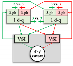
On the other hand, the correctness of the control unit function, as another safety requirement, can be verified through a comparison of the algorithms running in parallel paths (
Table 2). Signals 3 vs. 3 represent the comparison of three-phase systems. This can be accomplished with speed or torque, but is often done using current, since its high dynamic. Microcontroller or software functionality was the point of comparison shown in
Table 2, where the same control algorithms (for the same three-phase star) were run in parallel and compared. Any difference within a system denotes an error in the control unit (physical layer of processor or software). Such a technique should be available even in conditions of one three-phase system fault, which can be more elegantly demonstrated using the 1 d-q control structure, because 2 d-q control would have to run four three-phase control loops to achieve the same asset. For the
n × 3-phase machine controlled in
n d-q control frames,
2 × n control loops would be required, necessitating quite a large algorithm for control unit safety compliance.


