Article

Virtual and Physical Prototyping of Reconfigurable Parallel Mechanisms with Single Actuation

1
Mechanisms Theory and Machines Structure Laboratory, Mechanical Engineering Research Institute of the Russian Academy of Sciences (IMASH RAN), 101000 Moscow, Russia
2
LARM2: Laboratory of Robot Mechatronics, University of Rome “Tor Vergata”, 00133 Rome, Italy
*
Authors to whom correspondence should be addressed.
Appl. Sci. 2021, 11(15), 7158; https://doi.org/10.3390/app11157158
Submission received: 27 June 2021 / Revised: 27 July 2021 / Accepted: 28 July 2021 / Published: 3 August 2021
(This article belongs to the Special Issue Innovative Robot Designs and Approaches)

Abstract

:
The paper presents novel models of reconfigurable parallel mechanisms (RPMs) with a single active degree-of-freedom (1-DOF). The mechanisms contain three to six identical kinematic chains, which provide three (for the tripod) to zero (for the hexapod) uncontrollable DOFs. Screw theory is applied to carry out mobility analysis and proves the existence of controllable and uncontrollable DOFs of these mechanisms. Each kinematic chain in the synthesized mechanisms consists of planar and spatial parts. Such a design provides them with reconfiguration capabilities even when the driving link is fixed. This allows reproduction of diverse output trajectories without using additional actuators. In this paper, the model of a mechanism with six kinematic chains (hexapod) has been virtually and physically prototyped. The designing and assembling algorithms are developed using the detailed computer-aided design (CAD) model, which was further used to carry out kinetostatic analysis considering complex geometry of mechanism elements and friction among all contacting surfaces of joints. The developed virtual prototype and its calculation data have been further applied to fabricate mechanism elements and assemble an actuated full-scale physical prototype for future testing.

1. Introduction

Currently, designing full-scale models (physical prototyping) is often associated with the development of their digital twins (virtual prototyping), which, in fact, allows for beginning the product development process. Virtual prototyping is the process of designing a mechanical system in the form of a numerical model, while physical prototyping is the process of creating a real full-scale model. A virtual prototype allows for carrying out many numerical experiments using a computer functionality, which significantly reduces the time, physical and financial costs for creating a real model.
The processes of virtual and physical prototyping complement each other and allow for creating more advanced structures, providing maximum opportunities for consideration of the design requirements [1]. Today, advanced technologies allow for creating a real prototype based on a digital model of a mechanical system in quite a short time. Rapid prototyping technologies are widely used in this direction, in particular, 3D printing technologies with application of various materials [2]. In this field, the use of 3D printing technologies is quite popular both for soft [3,4,5] and solid [6,7,8] systems.
Let us consider some examples of using 3D printing technologies for parallel mechanisms and robots. Authors of [9] present a 6-DOF parallel mechanism designed as a cm sized six-component force sensor that measures the force information in space, including three-dimensional forces and three-dimensional torques. The mechanism has eight legs, each with grooves at both ends serving as spherical joints. A 5R 2-DOF parallel robotic arm for handling paper pot seedlings in a vegetable transplanter is proposed in [10]. The elements of the arm, including a gear box for its actuation, are 3D printed. Authors of [11] demonstrate a 3-DOF spatial compliant parallel mechanism for high-precision manipulation that was 3D printed from alloy Ti-6Al-4V. Authors of [12] present a spherical 3-RRR manipulator with coaxial input shafts. The manipulator design allows for unlimited rotational capability around the vertical axis. Another 3D printed spherical 3-RRR manipulator is shown in [13]. It applies as a shoulder of a prosthetic device. Authors of [14] consider the optimal design of one more spherical 3-RRR manipulator. The structure of one leg was changed to reduce the singularities within the workspace. Authors of [15] present a reconfigurable parallel mechanism with RRPS chains, where only prismatic joints are actuated and a base-coupled revolute joint in each chain can lock or turn during the mechanism motion. Authors of [16] show a 3-DOF parallel manipulator designed as a tripod. This manipulator can be used as a leg for walking systems.
The presented research is directed at virtual and physical prototyping of the mechanism, which belongs to a class of reconfigurable parallel mechanisms (RPMs). Mechanisms of this type can change their configurations to reproduce various end-effector trajectories or vary workspace dimensions. These mechanisms can also change the number of DOFs when their structure remains unchanged [17,18]. Some RPMs provide change-type of end-effector movements when passing through singular positions [19]. Such mechanisms also have the key advantages of parallel systems: high rigidity, ability to manipulate heavy loads and high positioning accuracy [20,21,22]. Possible practical applications of RPMs include rehabilitation medicine [23], gripping operations [24], additive technologies [25,26], machine elements processing [27,28,29] and force sensors [30].
One should note that the RPMs in the studies mentioned above include multiple actuators. It makes their structure and control more complex. In this study, we present a model of a novel RPM with the least possible number of actuators, i.e., with one actuator. In contrast to the known RPMs, the presented one does not have additional kinematic chains or modular elements, which are used only for reconfiguration.
In this regard, the proposed study aims to develop the virtual and physical prototyping algorithms for the RPMs actuated from a single drive. The physical prototyping is based on the 3D printing technologies.
The rest of the paper is organized as follows. Section 2 discusses different mechanism designs of the created RPMs having three to six legs and mobility from four to one. Section 3 follows next and provides structural analysis performed via screw theory. Section 4 shows a virtual prototyping algorithm for the hexapod with a single active DOF. This section also includes CAD calculations of the moment on the driving link (kinetostatic analysis). Based on the previous parts, a physical prototyping algorithm that includes 3D printing technologies finishes Section 4. Section 5 finalizes the study and provides conclusions.

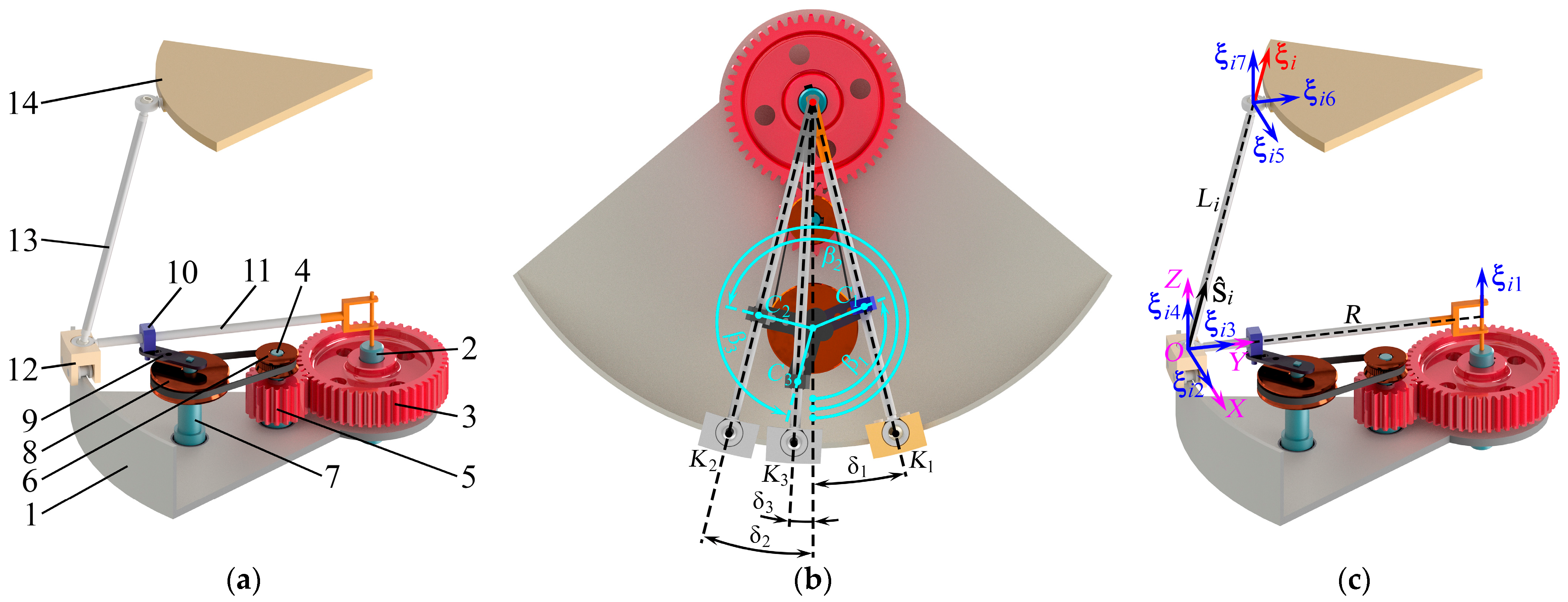
2. Mechanisms Design

This paper proposes a new kinematic chain design that provides reconfigurability. Figure 1a shows this kinematic chain that consists of links 4–13 and is coupled between the fixed (circular guide 1), driving (shaft 2 and wheel 3 forming a single element) and output (platform 14) links. This chain includes the following elements: shaft 4, gear 5 and driving pulley 6, which form a single link (rigid connection); shaft 7, driven pulley 8 and crank 9, which also organize a single link (rigid connection); slide block 10; swinging arm 11 and carriage 12, which also form a single link (rigid connection); and leg 13, which ends with the spherical joints at both sides. Figure 1b demonstrates reconfigurable capabilities of the chain. Here, the same carriage can provide different displacements δ1, δ2 and δ3, which correspond to the crank angles β1, β2 and β3 with the fixed driving wheel.
We can synthesize different mechanisms by connecting the output link to the base with several kinematic chains, shown in Figure 1a. Figure 2a–d present possible mechanisms as CAD models with three to six kinematic chains. In each chain, the input motion passes from driving links 2–3 to a link group of shaft 4, gear 5 and driving pulley 6. Next, the motion passes through the belt to a link group of shaft 7, driven pulley 8 and crank 9, which actuates swinging arm 11 through slide block 10. Swinging arm 11 displaces carriage 12 along circular guide 1. After that, the motion transmits to leg 13 and then to platform 14. Thus, the dependently actuated kinematic chains change position and orientation of platform 14 in space. In the following section, we will perform a mobility analysis of the obtained mechanisms and determine their number of DOFs.

3. Mobility Analysis

In this section, we will apply instantaneous screw theory to analyze mechanisms mobility. This theory is common for the analysis of parallel mechanisms and highly developed in recent years. Authors of [22,31,32] thoroughly discuss the features of this approach, and we recap the basics in Appendix A. We recommend the reader novel to the subject of instantaneous screws to look through these works or at least the appendix to appreciate the material of this section.

3.1. Analysis for a Single Kinematic Chain

First, we consider one kinematic chain and the unit twists that correspond to it. We will study only the spatial part: the planar part of each chain is a 1-DOF coulisse mechanism, and the rotational angle of the driving wheel uniquely determines the carriage position.
To begin with, we define coordinate system OXYZ, of which center O is in the center of the carriage spherical joint, as shown in Figure 1c. Let axis X be tangent to the circular guide, axis Y be directed along the swinging arm to its rotation axis and axis Z be orthogonal to the circular guide plane. Let ŝ i = [ s i x s i y s i z ] T be a unit vector directed from one spherical joint to the other, where i = 1…ni is an index of a kinematic chain, and ni = 3…6 is a number of chains depending on the mechanism structure shown in Figure 2a–d. Then, the platform twist system for one kinematic chain can be written as follows in this coordinate system:
ξ i 1 = [ 0 0 1 R 0 0 ] T , ξ i 2 = [ 1 0 0 0 0 0 ] T , ξ i 3 = [ 0 1 0 0 0 0 ] T , ξ i 4 = [ 0 0 1 0 0 0 ] T , ξ i 5 = [ 1 0 0 0 L i s i z L i s i y ] T , ξ i 6 = [ 0 1 0 L i s i z 0 L i s i x ] T , ξ i 7 = [ 0 0 1 L i s i y L i s i x 0 ] T ,
where ξi1 corresponds to the carriage motion along the circular guide; ξi2, ξi3 and ξi4 relate to the spherical motion in the carriage joint; ξi5, ξi6 and ξi7 relate to the spherical motion in the platform joint; R is a radius of the circular guide; and Li is a distance between the spherical joints (leg length).
We can compose matrix Ti, whose columns are twists (1), and examine its rank to determine if the kinematic chain constrains the platform motion or not. To obtain the rank, we can perform a Gaussian elimination procedure [33] (p. 97) and transform initial matrix Ti to the following upper triangle Ui:
U i = [ 1 1 0 0 1 0 0 0 R 0 0 R L i s i z L i s i y 0 0 1 0 0 1 0 0 0 0 1 0 0 1 0 0 0 0 L i s i z 0 L i s i x 0 0 0 0 0 L i s i x L i s i x s i y / s i z ] ,   if   s i z     0 , U i = [ 1 1 0 0 1 0 0 0 R 0 0 R 0 L i s i y 0 0 1 0 0 1 0 0 0 0 1 0 0 1 0 0 0 0 L i s i y L i s i x 0 0 0 0 0 0 0 L i s i x ] ,   if   s i z = 0 .
For a general chain configuration, there are no zero rows in matrix Ui; hence, the rank equals six. This means the chain does not impose any constraints on the platform motion (see Equation (A3) in Appendix A: only a zero wrench will satisfy it). However, in some configurations, the matrix can be rank deficient. For example, when s i x = 0 (the leg projects directly on the swinging arm), the rank equals five, and the chain imposes one constraint on the platform. Such configurations are known as leg singularities [34] and should be avoided during motion planning.
Let us consider the situation when the driving wheel is fixed. As we will see in the following subsection, this case is important for analyzing the mobility of the output link concerning several kinematic chains. In this case, the carriage does not move, and we can perform a similar analysis as above, leaving twist ξi1 out from matrix Ti. Corresponding upper triangle matrix Ui will have a form as below:
U i = [ 1 0 0 1 0 0 0 1 0 0 1 0 0 0 1 0 0 1 0 0 0 L i s i z 0 L i s i x 0 0 0 0 L i s i z L i s i y 0 0 0 0 0 0 ] .
The matrix above has a rank equal to five, and there exists one constraint on the platform by the chain. This constraint has wrench ζi reciprocal to twists ξi2ξi7 that can be found using Equation (A3) from Appendix A. Using this equation, we find:
ζ i = [ ŝ i T 0 T ] T .
The obtained wrench corresponds to a force directed along the leg and preventing the platform translation along this direction.

3.2. Analysis for Several Kinematic Chains

Now, let us consider the output link connected to the base by several kinematic chains. In the discussed mechanisms, all the chains are coupled through the driving wheel. To operate properly, the mechanism number of DOFs in a general (nonsingular) configuration should be equal to zero when the drive is fixed [22] (p. 40). If we fix the drive, each chain will impose wrench (4) on the output link. We can compose matrix W, whose columns represent these wrenches, and the number of columns will depend on the number of kinematic chains.
In the mechanisms with three, four and five kinematic chains (Figure 2a–c), there will be three, four and five wrenches ζi, respectively, acting on the platform. Hence, the rank of matrix W will always be less than six. This means we can find reciprocal twists, which will correspond to the uncontrolled movements (or uncontrolled DOFs) of the mechanism output link. Thus, the mentioned structures shown in Figure 2a–c cannot operate correctly with a single drive.
Fixing the drive in the mechanism with six kinematic chains shown in Figure 2d will lead to six wrenches ζi, and matrix W will have six columns. If the matrix has a full rank, the platform configuration is completely determined. The mechanism operates properly and has one (controlled) DOF. In some configurations, matrix W can be rank deficient, and the platform will obtain additional and uncontrolled DOFs. Such configurations represent another type of singularities common for parallel mechanisms [34] that should also be avoided for proper mechanism performance.
Table 1 summarizes the results of the mobility analysis, describing the reconfigurable solutions of the proposed kinematic chain. Thus, the only workable mechanism structure of the suggested ones is the one with six kinematic chains and single DOF shown in Figure 2d. We will study exactly this mechanism in the following sections.
Though the considered mechanism has only one DOF, a simple reconfiguration procedure, implying disconnecting the belts and reorienting the cranks (Figure 1b), allows for reproducing various output link trajectories, as we will see later in the paper. This is the key feature of the proposed design and the major benefit among other known reconfigurable mechanisms mentioned earlier in the introduction.

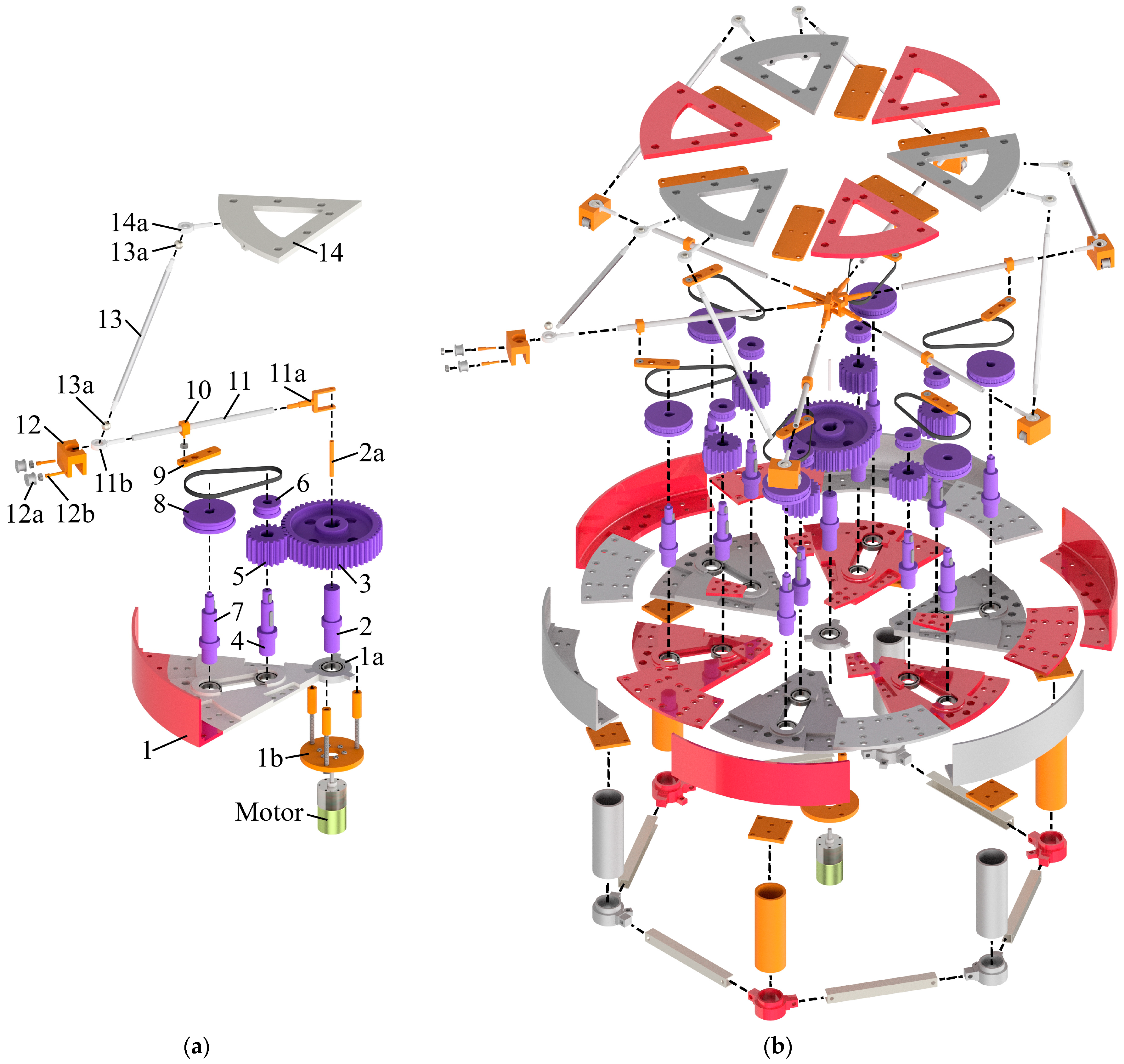
4. Virtual and Physical Prototyping

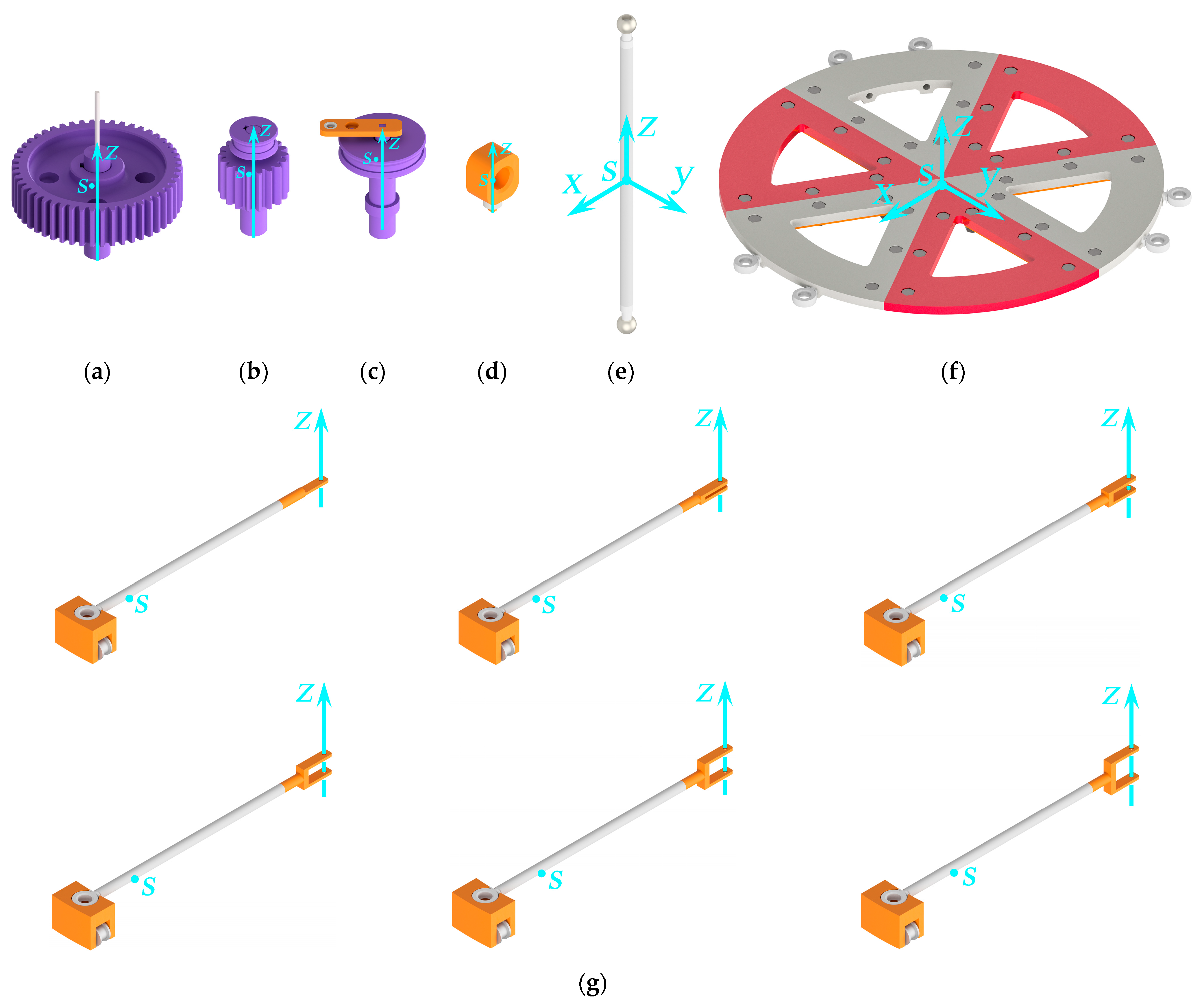
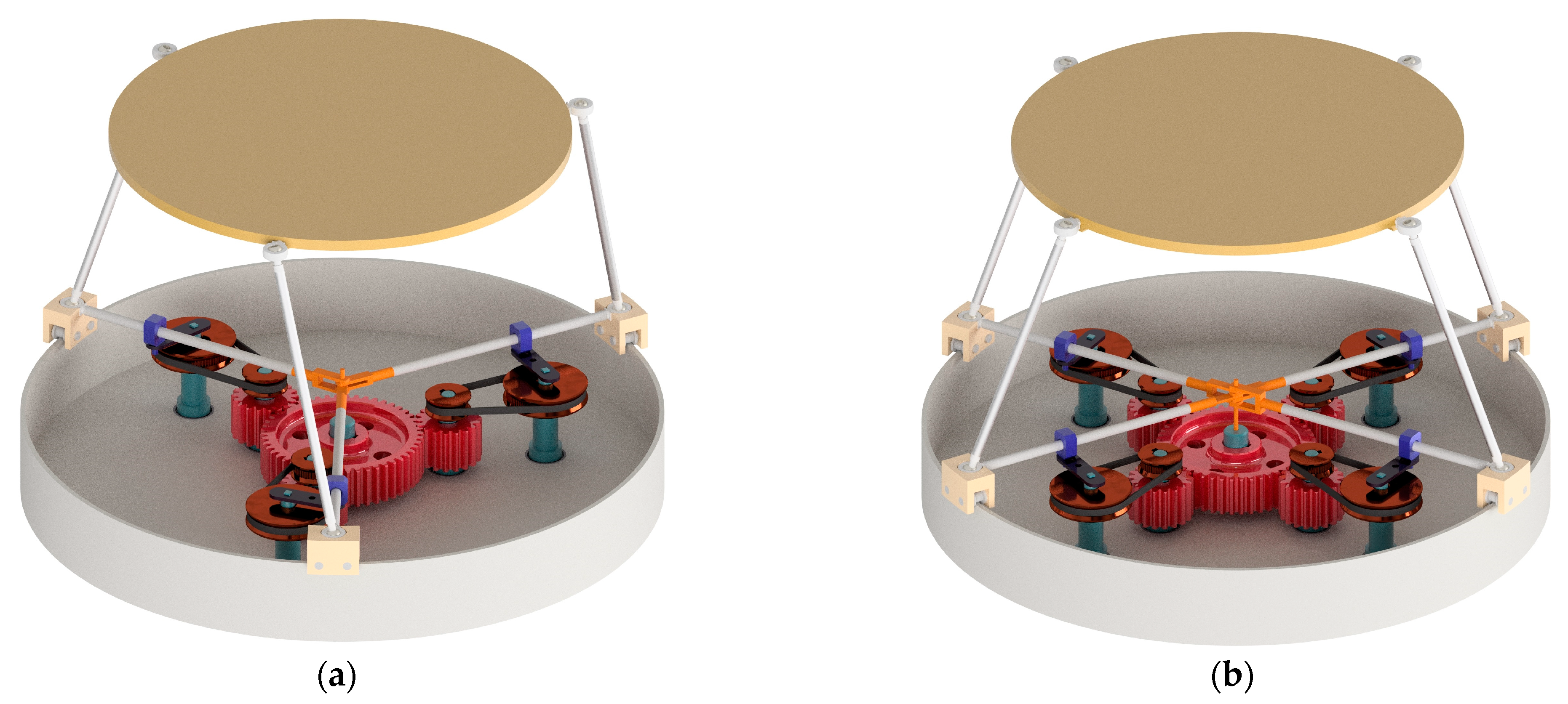
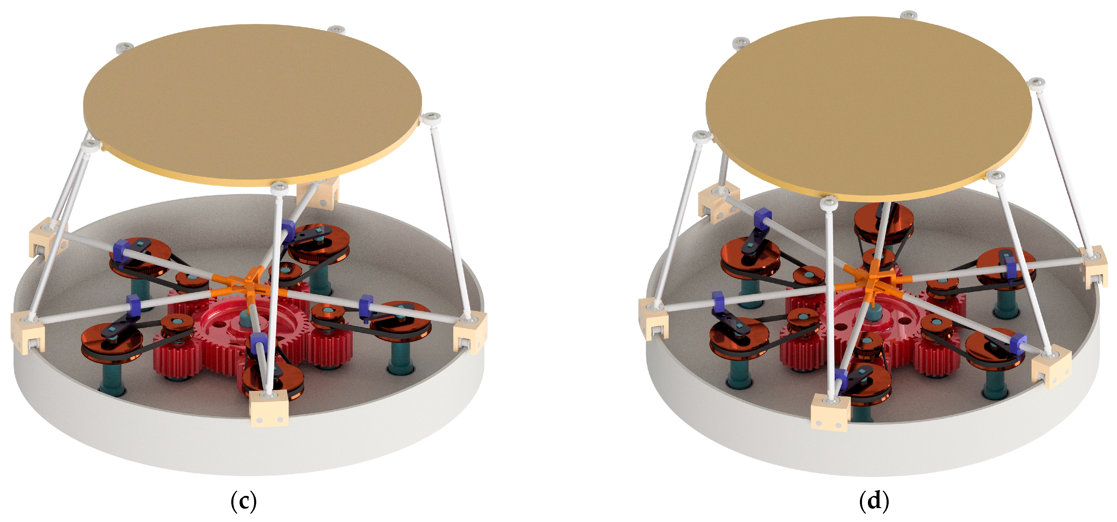
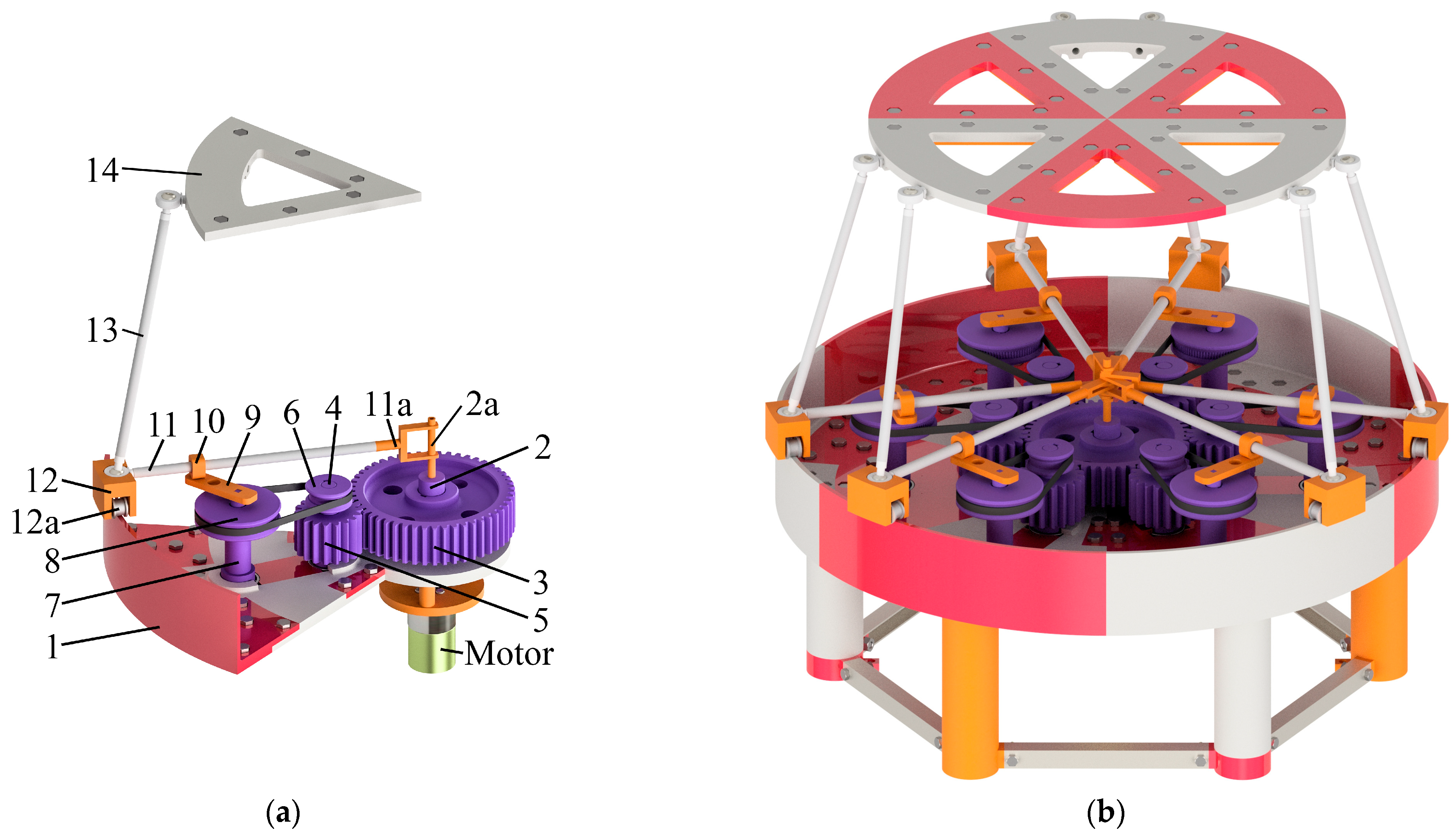
4.1. Development of the Hexapod CAD Model (Virtual Prototyping)

Based on the kinematic scheme of the 1-DOF hexapod shown in Figure 2d, we created its virtual prototype using CAD system Autodesk Inventor. Figure 3a,b show the exploded view of the hexapod assembly, considering the alignment and arrangement of all structural elements. This assembly allows for further manufacturing of these elements by 3D printing and using the standard machine elements.
The procedure for assembling the CAD model of the hexapod is as follows. It begins with assembling circular guide 1, divided into six sectors, comprising several parts, and central ring 1a with a rolling bearing pressed into it. Then, we mount a base consisting of six columns under circular guide 1. The columns connected by metal profiles absorb the load and give additional stability to the entire system. Next, a group of links that includes shaft 2 and driving wheel 3, forming a single link, is rigidly fixed in the center of circular guide 1. After that, we connect the electric motor shaft with shaft 2 under circular guide 1.
Further, we mount a group of links including shaft 4, gear 5 and driving pulley 6 in circular guide 1 through a rolling bearing. This group also forms a single link. After that, similarly, shaft 7 connects rigidly with driven pulley 8 and crank 9 and then becomes fixed in an adjacent bearing in circular guide 1. Next, we stretch the belt between driving 6 and driven 8 pulleys and install a spacer between the bearings of their shafts. Crank 9 and slide block 10 are connected by a rolling bearing.
The next group of links is a rigid connection of swinging arm 11 and carriage 12. Swinging arm 11 ends with fork 11a at one side for coupling with shaft 2a in the center of circular guide 1 and with lunule 11b of the spherical joint at another side. Fork 11a at each swinging arm has an individual geometry for locating them in one plane. Carriage 12 moves on the edge of circular guide 1 by a pair of rollers 12a, which are supported by shafts 12b. Lunule 11b is pressed into carriage 12, forming a single link of swimming arm 11 and carriage 12.
Similarly, we press balls 13a of the spherical joints into leg 13 on both sides. Platform 14, like circular guide 1, is divided into six sectors, connected by coupling plates. Further, three of these sectors connect rigidly with a pair of lunules 14a of the platform spherical joints.
Figure 4a,b show the assembled CAD model of the hexapod with all the structural elements discussed above. This model allows 3D printing its elements and using standard mechanical parts. Table 2 presents the geometrical dimensions of the hexapod elements.

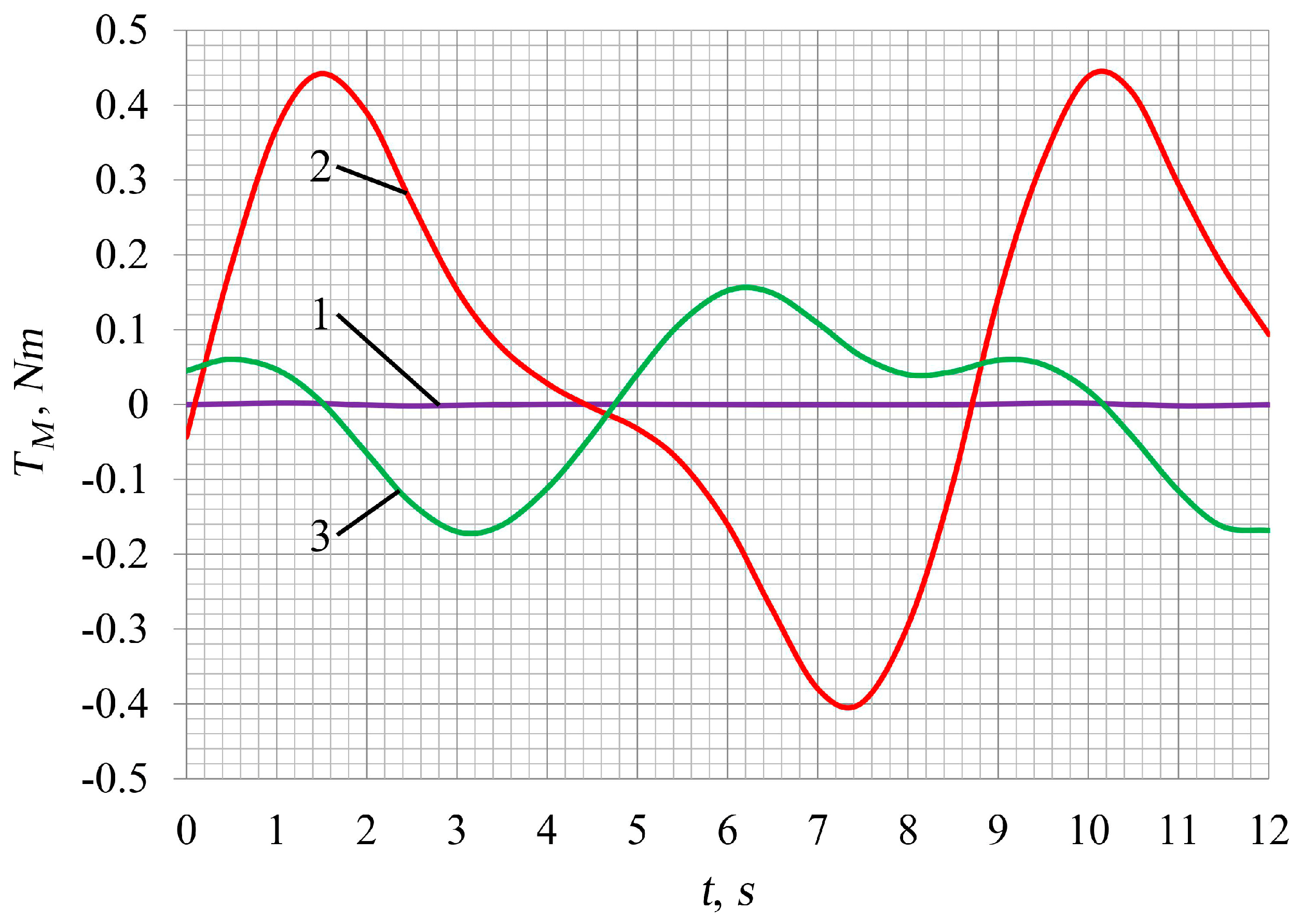
4.2. Kinetostatic Analysis of a Hexapod Using CAD Modeling

To select an appropriate electric motor for the hexapod, we need to perform its kinetostatic analysis and define a motor torque on the driving shaft 2. Let us accept the driving wheel rotates at a speed of 5 rpm. Due to the mechanism ability to reproduce differing trajectories of the output link, we consider several cases corresponding to our previous study [35]:
  • the output link performs a pure rotation around the vertical axis: βi = 255.8°, i = 1…6;
  • the output link performs a simultaneous rotation and displacement relative to the vertical axis: β1 = β3 = β5 = 104.2° and β2 = β4 = β6 = 255.8°;
  • the output link follows a spatial trajectory changing all six coordinates: β1 = 287.6°, β2 = 103.3°, β3 = 278.4°, β4 = 263.8°, β5 = 260.6°, β6 = 242.4°.
We have found these values of angles βi experimentally in CAD simulation. However, we could also apply a kind of inverse kinematics algorithm to find the angles. In this case, there exists a nontrivial numerical algorithm which can provide different solutions depending on an initial guess. We have touched on this problem in work [36]. The Supplementary Materials section presents movie of the CAD model operation with respect to the cases mentioned above.
We have performed the kinetostatic calculations using an Autodesk Inventor Dynamic Simulation module, which provides dynamic modeling with various parameters of the assembling CAD model. Table 3 presents the materials and inertial parameters of the mechanism structural elements. Inertia moments of the links in the planar part of the mechanism are determined relative to their rotational axes, and inertia tensors of the links that perform a spatial movement (legs 13 and platform 14) are calculated in their mass centers relative to the axes shown in Figure A1 (Appendix B).
The calculation included the friction between all mechanism elements. We set the following friction coefficients kf for the calculations: kf = 0.002 for the rolling bearings in the planar part; kf = 0.02 for sliding joints 10–11 (aluminum over ABS plastic); kf = 0.1 for spherical joints 12-13 and 13-14 (steel over steel); kf = 0.02 for the couplings of forks 11a with shaft 2a at the center of circular guide 1 (steel over ABS plastic). We also took efficiency ratios 0.98 and 0.95 for the gear and belt couplings, respectively.
Given the parameters above, we prepared the mechanism assembly (Figure 4) for dynamic modeling. Simulation results shown in Figure 5 present the calculated value of the motor torque (TM) for the different cases of cranks initial positions. Notice how the torque increases to compensate for the weight contribution of the links when the platform displaces along the vertical axis.
One should note that using CAD software to perform calculations allows for considering the links geometry and material as accurately as possible. Thereby, the CAD functionality can significantly simplify the solution process and lead to more accurate results in comparison with the analytical methods.

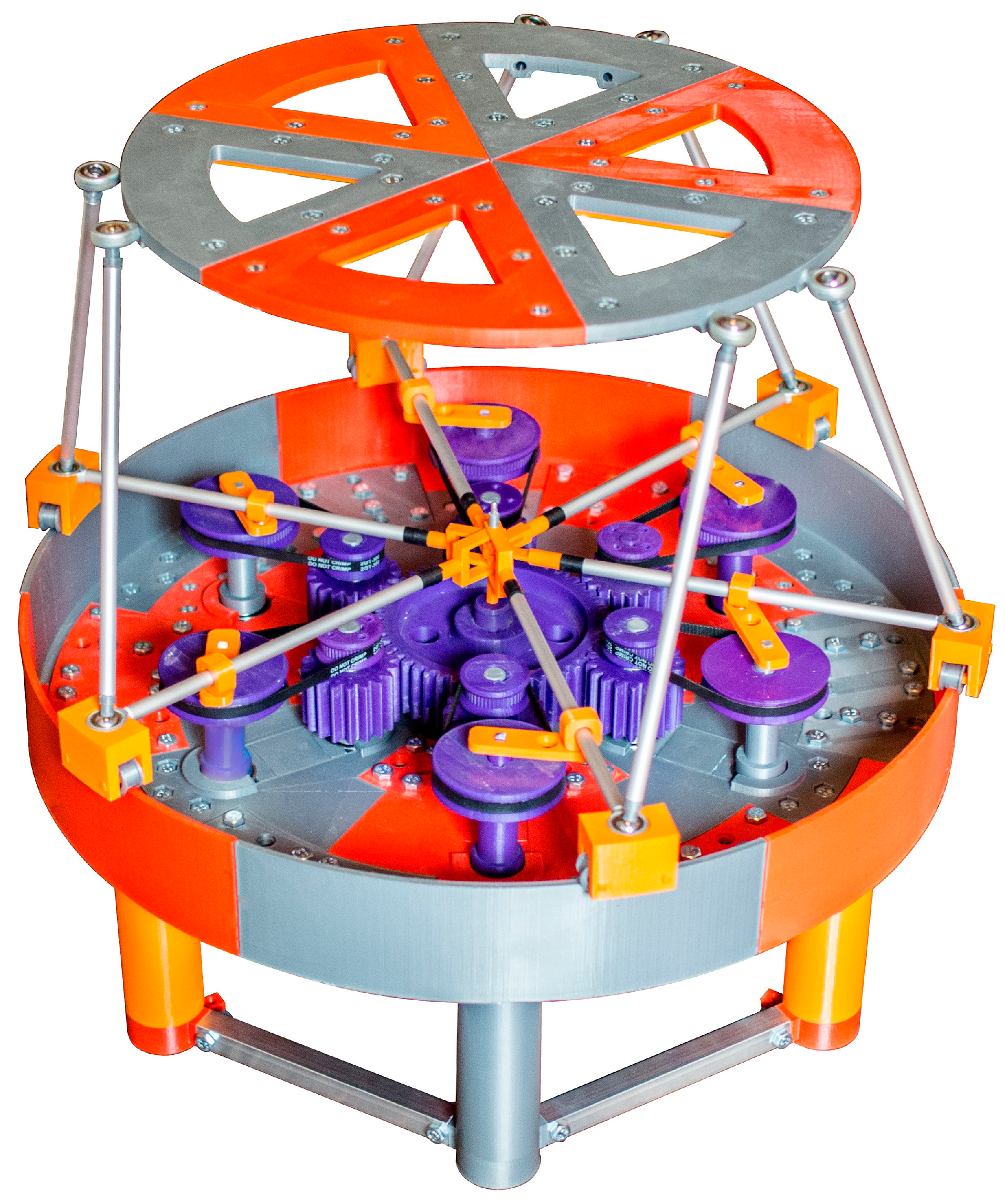
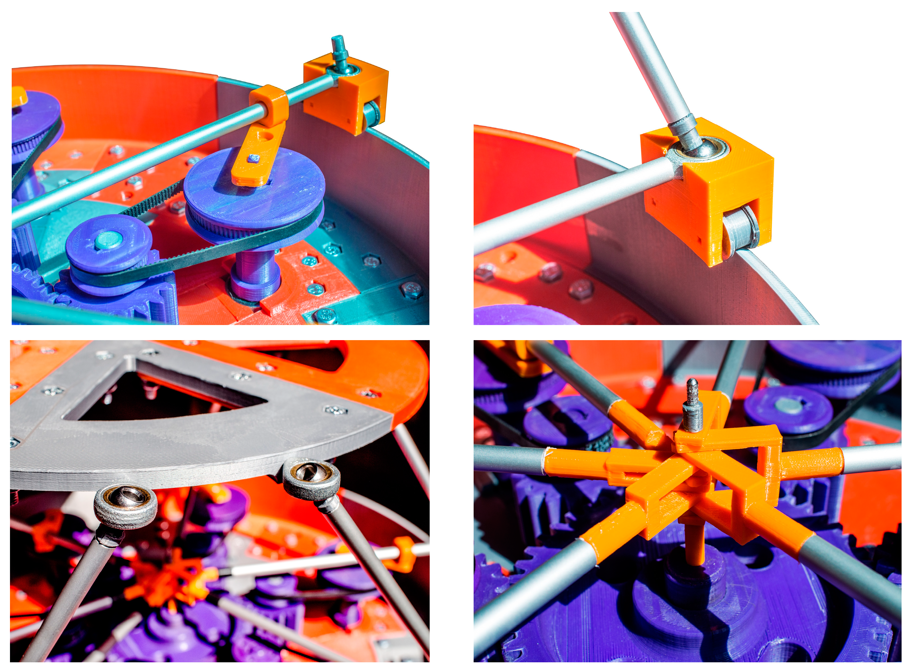
4.3. Development of a Hexapod Full-Scale Model (Physical Prototyping)

Based on the assembling model of the mechanism shown in Figure 4, we produced its physical prototype. Figure 6 shows the prototype picture, and the Supplementary Materials section presents a movie of the prototype functioning. Thus, the virtual prototype serves as a digital twin of the produced physical prototype. Most of the prototype links and couplings were 3D printed on Flsun QQ-S. Other components were easy-to-access standard elements, including legs 13 and swinging arms 11 made of round aluminum profiles, steel spherical joints and bearings. The mechanism drive was selected based on the motor torque calculation given in Section 4.2.
The major advantage of such a design is in using easy-to-access materials and components. Figure 7 shows some mechanism components: the belt drive; connection of the swinging arm, carriage and leg; the platform spherical joints; swinging arms connection in the center of the circular guide. The fork-like design of the swinging arms allows positioning all the arms in one plane. Geometrical parameters of the physical prototype correspond to its digital twin (virtual prototype) presented in Figure 4.
We have two opportunities to control the hexapod. The first and the simplest one is to rotate the motor at some constant speed. The output link will perform a cyclic motion, which depends on the initial orientations of the cranks. This method was presented in Section 4.2 and [35]. The second approach implies solving an inverse kinematics problem where we set the platform trajectory and calculate the required control law for the drive. However, since the mechanism has only one DOF, we can set the motion only for one platform coordinate, while the others are calculated from the inverse kinematics together with the drive motion. We addressed this problem in [36].

5. Conclusions

This paper has presented novel variations of RPMs with similar structure and a different number of kinematic chains. The mobility analysis of the mechanisms carried out via screw theory has provided a calculation of controllable and uncontrollable DOFs. It was found that 4-DOF tripod has three uncontrollable DOFs, 3-DOF quadropod has two uncontrollable DOFs, 2-DOF pentapod has one uncontrollable DOF and 1-DOF hexapod is fully controllable.
The reconfigurability of the mechanisms allows for changing the output link trajectories without using additional kinematic chains or drives. The proposed mechanisms have such design advantages as a drive fixed on the base, absence of the possibility of collisions between the adjacent carriages due to correctly chosen cranks lengths and diverse reconfigurable capabilities due to having a flexible coupling in each kinematic chain.
Based on the obtained mechanisms structures, the hexapod one (the mechanism with six kinematic chains) has been developed as an assembling CAD model, which allowed us to perform a numerical kinetostatic analysis and then fabricate an actuated physical prototype. The developed CAD model was adapted to using 3D printing technologies in prototype production.
The conducted research confirms that virtual and physical prototyping processes relate to each other, and their cooperative execution is very effective in product deve- lopment. In addition, rapid prototyping technologies, which are one of the most optimal ways to develop physical prototypes, can be often realized only with virtual prototyping.
Having the physical prototype built, we can aim our further research at its experimental study, including accuracy and repeatability tests, rigidity and load capacity analyses, tests for maximum operating speed and others. Additional research can be associated with an analysis of the presented hexapod for specific practical applications, such as rehabilitation procedures, where the hexapod platform could provide various types of cyclic motions. In this regard, the analysis would aim to calculate the initial cranks configuration and the motion laws of the driving link based on the predetermined platform displacements.

Supplementary Materials

The following are available online at: https://www.mdpi.com/article/10.3390/app11157158/s1, Video S1: Movie of the CAD model operation, Video S2: Movie of the physical prototype operation.

Author Contributions

Conceptualization, A.F. and A.A.; methodology, A.F. and A.A.; software, A.F. and D.P.; validation, A.F. and D.P.; formal analysis, A.F. and A.A.; investigation, A.F., D.P. and A.A.; resources, A.F., D.P., A.A. and V.G.; writing—original draft preparation, A.F., A.A. and M.C.; writing—review and editing, A.F. and A.A.; visualization, A.F. and D.P.; supervision, A.F., A.A. and V.G.; project administration, A.F.; funding acquisition, M.C. All authors have read and agreed to the published version of the manuscript.

Funding

This research was supported by Russian Science Foundation (RSF) under grant № 21-79-10409, https://rscf.ru/project/21-79-10409/.

Institutional Review Board Statement

Not applicable.

Informed Consent Statement

Not applicable.

Data Availability Statement

The data presented in this study are available on request from the corresponding author.

Conflicts of Interest

The authors declare that they have no conflict of interest.

Appendix A. Basics of Instantaneous Screw Theory

The major idea of screw theory relies on Chasles’ theorem [32] (p. 26), by which any finite motion of a rigid body can be represented as a combination of rotation about some axis and translation parallel to it. This axis is called a screw axis. If the motion is infinitesimal, we can consider it instantaneous, and the screw axis becomes an instantaneous screw axis. This instantaneous screw motion can be characterized by three basic elements: the axis itself, the angular speed about this axis and the linear speed along it. We can combine these elements into a 6-D vector called (instantaneous) screw ξ [32] (p. 40):
ξ = ω [ ŝ r × ŝ ] + υ [ 0 ŝ ] ,
where ŝ is a unit vector directed along the screw axis; r is a vector pointed from the origin of the coordinate system to any point on the screw axis; ω is an angular speed relative to the screw axis; and υ is a linear speed about the screw axis.
An alternative common notation for a screw implies using scalar parameters: magnitude s and pitch h = υ/ω. In this case, a screw can be defined as follows [22] (p. 19):
ξ = s [ ŝ r × ŝ + h ŝ ] ,   if   h     , ξ = s [ 0 ŝ ] ,   if   h =   .
Similarly, all the forces and moments acting on a rigid body can be reduced to a force directed along some axis and a moment about the axis. We can define screw ζ representing this resulting force and moment using relations similar to (A1) and (A2). To differ between these screws, terms twist and wrench are usually applied for ξ and ζ, respectively. Twists and wrenches of zero pitch (h = 0) correspond to pure rotations and forces. Twists and wrenches of infinite pitch (h = ∞) correspond to pure translations and moments.
Screws can be summed with each other and multiplied by a scalar—these properties allow screws to form vector spaces. Thus, the space of twists can define the possible velocities of the rigid body, while the space of wrenches represents all the forces and moments acting on it. If each twist ξ from the twist space and each wrench ζ from the wrench space satisfy the following condition [22] (p. 24):
ξ     ζ = ( P ξ ) T ζ = 0 ,
where P is a permutation matrix of the form:
P = [ 0 3 × 3 I 3 × 3 I 3 × 3 0 3 × 3 ] ,
then the wrench space represents all forces and torques that constrain the body motion. Operation “∘” is known as a reciprocal product, and screws ξ and ζ that satisfy condition (A3) are reciprocal.
If two bodies are connected by a series of joints, we can associate unit twist ξj (s = 1 in expression (A2)) j = 1…m with each joint, where m is a number of joints. Then, twist system T comprising twists ξ1, ξ2, …, ξm will define the space of possible velocities of one body relative to the other. The reciprocal wrench system W (each wrench of which is reciprocal to each twist of system T) corresponds to constraints between the bodies.
For a parallel mechanism with n kinematic chains, each having mi joints, i = 1…n, we can define twists systems Ti of unit twists ξij, j = 1…mi, associated with each chain. Wrench system Wi reciprocal to Ti corresponds to constraints that the i-th chain imposes on the motion of the output link. Considering all the kinematic chains, the output link motion will be constrained such that its resulting wrench system W is a union of all wrench systems Wi. Finally, twist system T reciprocal to W will define all the possible velocities the output link can attain. One should never forget that all the screws are instantaneous, and the results of the analysis performed above depend on a particular mechanism configuration. In some configurations, twist or wrench systems can include linearly dependent screws. Such situations are known as singularities, and the mechanism can lose or gain degrees of freedom in singular configurations, or even change its motion type when passing through them. Authors of [34] present a thorough analysis of this topic.

Appendix B. Hexapod Elements Geometry

Figure A1 shows hexapod links with identified mass centers and axes used to calculate the inertia parameters. The links shown in Figure A1a–d,g rotate around the fixed axes, and their inertia moments are calculated relative to these axes. The inertia tensors for the links having spatial motion shown in Figure A1e,f are calculated with respect to the depicted coordinate systems placed at the mass centers. The links in Figure A1a,b have displaced mass centers because of the shaft keys.
Figure A1. Definition of the inertia terms based on the hexapod elements geometry.
Applsci 11 07158 g0a1

References

  1. Gibson, I.; Gao, Z.; Campbell, I. A comparative study of virtual prototyping and physical prototyping. Int. J. Manuf. Technol. Manag. 2004, 6, 503–522. [Google Scholar] [CrossRef]
  2. Chen, L.; Daly, M.C.; Sabelhaus, A.P.; Janse van Vuuren, L.A.; Garnier, H.J.; Verdugo, M.I.; Tang, E.; Spangenberg, C.U.; Ghahani, F.; Agogino, A.M.; et al. Modular elastic lattice platform for rapid prototyping of tensegrity robots. In Proceedings of the ASME 2017 International Design Engineering Technical Conferences and Computers and Information in Engineering Conference, Volume 5B: 41st Mechanisms and Robotics Conference, Cleveland, OH, USA, 6–9 August 2017. V05BT08A026. [Google Scholar] [CrossRef] [Green Version]
  3. Wallin, T.J.; Pikul, J.; Shepherd, R.F. 3D printing of soft robotic systems. Nat. Rev. Mater. 2018, 3, 84–100. [Google Scholar] [CrossRef]
  4. Gul, J.Z.; Sajid, M.; Rehman, M.M.; Siddiqui, G.U.; Shah, I.; Kim, K.-H.; Lee, J.-W.; Choi, K.H. 3D printing for soft robotics—A review. Sci. Technol. Adv. Mater. 2018, 19, 243–262. [Google Scholar] [CrossRef] [PubMed] [Green Version]
  5. Skylar-Scott, M.A.; Mueller, J.; Visser, C.W.; Lewis, J.A. Voxelated soft matter via multimaterial multinozzle 3D printing. Nature 2019, 575, 330–335. [Google Scholar] [CrossRef]
  6. Lapeyre, M.; Rouanet, P.; Grizou, J.; Nguyen, S.; Depraetre, F.; Le Falher, A.; Oudeyer, P.-Y. Poppy Project: Open-Source fabrication of 3D printed humanoid robot for science, education and art. In Proceedings of the Digital Intelligence, Nantes, France, 17–19 September 2014. [Google Scholar]
  7. Chavdarov, I.; Nikolov, V.; Naydenov, B.; Boiadjiev, G. Design and control of an educational redundant 3D printed robot. In Proceedings of the 2019 International Conference on Software, Telecommunications and Computer Networks (SoftCOM), Split, Croatia, 19–21 September 2019. [Google Scholar] [CrossRef]
  8. Ficht, G.; Farazi, H.; Brandenburger, A.; Rodriguez, D.; Pavlichenko, D.; Allgeuer, P.; Hosseini, M.; Behnke, S. NimbRo-OP2X: Adult-sized open-source 3D printed humanoid robot. In Proceedings of the 2018 IEEE-RAS 18th International Conference on Humanoid Robots (Humanoids), Beijing, China, 6–9 November 2018; pp. 1–9. [Google Scholar] [CrossRef] [Green Version]
  9. Yao, J.; Zhang, H.; Xiang, X.; Bai, H.; Zhao, Y. A 3-D printed redundant six-component force sensor with eight parallel limbs. Sens. Actuator A Phys. 2016, 247, 90–97. [Google Scholar] [CrossRef]
  10. Rahul, K.; Raheman, H.; Paradkar, V. Design and development of a 5R 2DOF parallel robot arm for handling paper pot seedlings in a vegetable transplanter. Comput. Electron. Agric. 2019, 166, 105014. [Google Scholar] [CrossRef]
  11. Pham, M.T.; Teo, T.J.; Yeo, S.H.; Wang, P.; Nai, M.L.S. A 3-D printed Ti-6Al-4V 3-DOF compliant parallel mechanism for high precision manipulation. IEEE/ASME Trans. Mechatron. 2017, 22, 2359–2368. [Google Scholar] [CrossRef]
  12. Tursynbek, I.; Niyetkaliye, A.; Shintemirov, A. Computation of unique kinematic solutions of a spherical parallel manipulator with coaxial input shafts. In Proceedings of the 2019 IEEE 15th International Conference on Automation Science and Engineering (CASE), Vancouver, BC, Canada, 22–26 August 2019; pp. 1524–1531. [Google Scholar] [CrossRef]
  13. Leal-Naranjo, J.-A.; Ceccarelli, M.; Torres-San-Miguel, C.-R.; Aguilar-Perez, L.-A.; Urriolagoitia-Sosa, G.; Urriolagoitia-Calderón, G. Multi-objective optimization of a parallel manipulator for the design of a prosthetic arm using genetic algorithms. Lat. Am. J. Solids Struct. 2018, 15, e26. [Google Scholar] [CrossRef] [Green Version]
  14. Saafi, H.; Laribi, M.A.; Arsicault, M.; Zeghloul, S. Optimal design of a new spherical parallel manipulator. In Proceedings of the 2014 23rd International Conference on Robotics in Alpe-Adria-Danube Region (RAAD), Smolenice, Slovakia, 3–5 September 2014; pp. 1–6. [Google Scholar] [CrossRef]
  15. Grosch, P.; Di Gregorio, R.; Lopez, J.; Thomas, F. Motion planning for a novel reconfigurable parallel manipulator with lockable revolute joints. In Proceedings of the 2010 IEEE International Conference on Robotics and Automation (ICRA), Anchorage, AK, USA, 3–7 May 2010; pp. 4697–4702. [Google Scholar] [CrossRef] [Green Version]
  16. Russo, M.; Ceccarelli, M. Kinematic design of a tripod parallel mechanism for robotic legs. In Mechanisms, Transmissions and Applications, Proceedings of the Fourth MeTrApp Conference 2017, Poitiers, France, 22–24 May 2017; Dede, M., İtik, M., Lovasz, E.C., Kiper, G., Eds.; Springer: Cham, Switzerland, 2018; pp. 121–130. [Google Scholar] [CrossRef]
  17. Fanghella, P.; Galletti, C.; Giannotti, E. Parallel robots that change their group of motion. In Advances in Robot Kinematics, Proceedings of the 10th International Symposium on Advances in Robot Kinematics, Ljubljana, Slovenia, 26–29 June 2006; Lenarčič, J., Roth, B., Eds.; Springer: Dordrecht, The Netherlands, 2006; pp. 49–56. [Google Scholar] [CrossRef]
  18. Ye, W.; Chai, X.; Zhang, K. Kinematic modeling and optimization of a new reconfigurable parallel mechanism. Mech. Mach. Theory 2020, 149, 103850. [Google Scholar] [CrossRef]
  19. Kong, X.; Gosselin, C.M.; Richard. P. Type synthesis of parallel mechanisms with multiple operation modes. J. Mech. Des. 2007, 129, 595–601. [Google Scholar] [CrossRef]
  20. Merlet, J.-P. Parallel Robots, 2nd ed.; Springer: Dordrecht, The Netherlands, 2006. [Google Scholar] [CrossRef]
  21. Ceccarelli, M. Fundamentals of Mechanics of Robotic Manipulation; Springer: Dordrecht, The Netherlands, 2004. [Google Scholar] [CrossRef]
  22. Kong, X.; Gosselin, C.M. Type Synthesis of Parallel Mechanisms; Springer: Berlin/Heidelberg, Germany, 2007. [Google Scholar] [CrossRef]
  23. Zhang, M.; Cao, J.; Zhu, G.; Miao, Q.; Zeng, X.; Xie, S.Q. Reconfigurable workspace and torque capacity of a compliant ankle rehabilitation robot (CARR). Robot. Auton. Syst. 2017, 98, 213–221. [Google Scholar] [CrossRef] [Green Version]
  24. Herrero, S.; Mannheim, T.; Prause, I.; Pinto, C.; Corves, B.; Altuzarra, O. Enhancing the useful workspace of a reconfigurable parallel manipulator by grasp point optimization. Robot. Comput. Integr. Manuf. 2015, 31 (Suppl. C), 51–60. [Google Scholar] [CrossRef]
  25. Tian, C.; Fang, Y.; Guo, S.; Qu, H. A class of reconfigurable parallel mechanisms with five-bar metamorphic linkage. Proc. Inst. Mech. Eng. C J. Mech. 2016, 231, 2089–2099. [Google Scholar] [CrossRef]
  26. Ye, W.; Fang, Y.; Guo, S. Design and analysis of a reconfigurable parallel mechanism for multidirectional additive manufacturing. Mech. Mach. Theory 2017, 112, 307–326. [Google Scholar] [CrossRef] [Green Version]
  27. Li, Q.; Xu, L.; Chen, Q.; Ye, W. New family of RPR-equivalent parallel mechanisms: Design and application. Chin. J. Mech. Eng. 2017, 30, 217–221. [Google Scholar] [CrossRef]
  28. Carbonari, L.; Callegari, M.; Palmieri, G.; Palpacelli, M.-C. A new class of reconfigurable parallel kinematic machines. Mech. Mach. Theory 2014, 79, 173–183. [Google Scholar] [CrossRef]
  29. Bi, Z.; Wang, L. Optimal design of reconfigurable parallel machining systems. Robot. Comput. Integr. Manuf. 2009, 25, 951–961. [Google Scholar] [CrossRef]
  30. Huang, G.; Zhang, D.; Guo, S.; Qu, H. Design and optimization of a novel three-dimensional force sensor with parallel structure. Sensors 2018, 18, 2416. [Google Scholar] [CrossRef] [PubMed] [Green Version]
  31. Huang, Z.; Li, Q.; Ding, H. Theory of Parallel Mechanisms; Springer: Dordrecht, The Netherlands, 2013. [Google Scholar] [CrossRef]
  32. Sun, T.; Yang, S.; Lian, B. Finite and Instantaneous Screw Theory in Robotic Mechanism; Springer: Singapore, 2020. [Google Scholar] [CrossRef]
  33. Strang, G. Introduction to Linear Algebra, 5th ed.; Wellesley-Cambridge Press: Wellesley, MA, USA, 2016. [Google Scholar]
  34. Conconi, M.; Carricato, M. A new assessment of singularities of parallel kinematic chains. IEEE Trans. Rob. 2009, 25, 757–770. [Google Scholar] [CrossRef]
  35. Fomin, A.; Antonov, A.; Glazunov, V. Forward kinematic analysis of a rotary hexapod. In ROMANSY 23-Robot Design, Dynamics and Control, Proceedings of the 23rd CISM IFToMM Symposium, Sapporo, Japan, 20–24 September 2020; Venture, G., Solis, J., Takeda, Y., Konno, A., Eds.; Springer: Cham, Switzerland, 2021; pp. 486–494. [Google Scholar] [CrossRef]
  36. Fomin, A.; Antonov, A.; Glazunov, V.; Carbone, G. Dimensional (parametric) synthesis of the hexapod-type parallel mechanism with reconfigurable design. Machines 2021, 9, 117. [Google Scholar] [CrossRef]
Figure 1. CAD schemes of the single reconfigurable kinematic chain: (a) main components: circular guide 1 (fixed link); shaft 2 and wheel 3 (driving link); shaft 4, gear 5 and driving pulley 6; shaft 7, driven pulley 8 and crank 9; slide block 10; swinging arm 11 and carriage 12; leg 13; and platform 14 (output link); (b) reconfigurable positions of the chain with carriage displacements δ1, δ2 and δ3, corresponding to the crank angles β1, β2 and β3 with the fixed driving wheel; (c) twists for a single kinematic chain and a reciprocal wrench for the chain with the locked drive.
Applsci 11 07158 g001
Figure 2. CAD models of the synthesized mechanisms with a reconfigurable design: (a) tripod; (b) quadropod; (c) pentapod; (d) hexapod.
Applsci 11 07158 g002aApplsci 11 07158 g002b
Figure 3. Exploded view of the structural elements assembly (CAD model) of the proposed hexapod: (a) single kinematic chain with a driving part; (b) complete mechanism model.
Applsci 11 07158 g003
Figure 4. Assembling virtual prototype (CAD model) of the hexapod: (a) single kinematic chain with a driving part; (b) complete mechanism model.
Applsci 11 07158 g004
Figure 5. Time-dependent diagrams of the hexapod motor torque (TM) for the different cranks initial positions: 1—{βi = 255.8°}, the output link only rotates around the vertical axis; 2—{β1 = β3 = β5 = 104.2° and β2 = β4 = β6 = 255.8°}, the output link has simultaneous rotation and displacement relative to the vertical axis; 3—{β1 = 287.6°, β2 = 103.3°, β3 = 278.4°, β4 = 263.8°, β5 = 260.6°, β6 = 242.4°}, the output link performs general spatial motion changing all six coordinates.
Applsci 11 07158 g005
Figure 6. The actuated full-scale physical prototype of the proposed hexapod.
Applsci 11 07158 g006
Figure 7. The main units of motion transmission of the proposed hexapod.
Applsci 11 07158 g007
Table 1. Summary of the mobility analysis results.
Number of
Kinematic Chains
Number of DOFs of the Output Link
OverallControllableUncontrollable
3413
4312
5211
611
Table 2. Geometrical dimensions of the hexapod links.
Parameter NomenclatureDimension
Overall dimensions of the hexapod, including the maximum displacements of the platform530 mm × 530 mm × 457 mm
(LWH dimensions)
Column height of circular guide 1143.00 mm
Diameter of circular guide 1500.00 mm
Height of circular guide 158.30 mm
Pitch diameter of driving wheel 3125.00 mm
Number of teeth of driving wheel 350
Pitch diameter of gear 545.00 mm
Number of teeth of gear 518
Center distance of gear transmission 3–585.00 mm
Module of gears 3–52.50 mm
Diameter of driving pulley 630.00 mm
Diameter of driven pulley 860.00 mm
Center distance of belt transmission 6–876.00 mm
Length of crank 938.85 mm
Length of swinging arm 11 (distance from the center of circular guide 1 to the center of spherical joint 12–13)246.05 mm
Length of leg 13220.05 mm
Platform radius 14 excluding spherical joints 13–14180.00 mm
Platform radius 14 including spherical joints 13–14 (distance from the center of platform 14 to the center of spherical joint 13–14)193.00 mm
Minimum/maximum angle between paired spherical joints 13–14 20°/100°
Bearing 1,000,804 (13 pcs)20 mm × 32 mm × 7 mm
Bearing 623ZZ (18 pcs)3 mm × 10 mm × 4 mm
Diameter of the sphere in the spherical joints 12.00 mm
Table 3. Inertial properties of the hexapod links.
Link/Group of LinksMaterialMoment of Inertia, kg∙mm2Mass, kg
Shaft 2 and driving wheel 3 Plastic ABS494.190.257
Shaft 4, gear 5 and driving pulley 6Plastic ABS20.680.091
Shaft 7, driven pulley 8 and crank 9Plastic ABS32.040.085
Slide block 10Plastic ABS0.0610.003
Swinging arm 11 (incl. elements 11a,b),
and carriage 12 (incl. elements 12a,b)
#1Aluminum, plastic ABS, steel2545.400.052
#22545.660.052
#32545.760.053
#42545.870.053
#52545.800.053
#62546.090.053
Leg 13 (incl. elements 13a)Aluminum, plastic ABS, steel [ 159 . 87   0 0 0 159 . 87   0 0 0 0 . 33 ] 0.022
Platform 14 (incl. elements 14a)Aluminum, plastic ABS, steel [ 10061 . 20 0 0 0 10061 . 20 0 0 0 20079 . 61 ] 1.153
Publisher’s Note: MDPI stays neutral with regard to jurisdictional claims in published maps and institutional affiliations.

