
Time-Division Color Holographic Projection in Large Size Using a Digital Micromirror Device †


Abstract
:1. Introduction
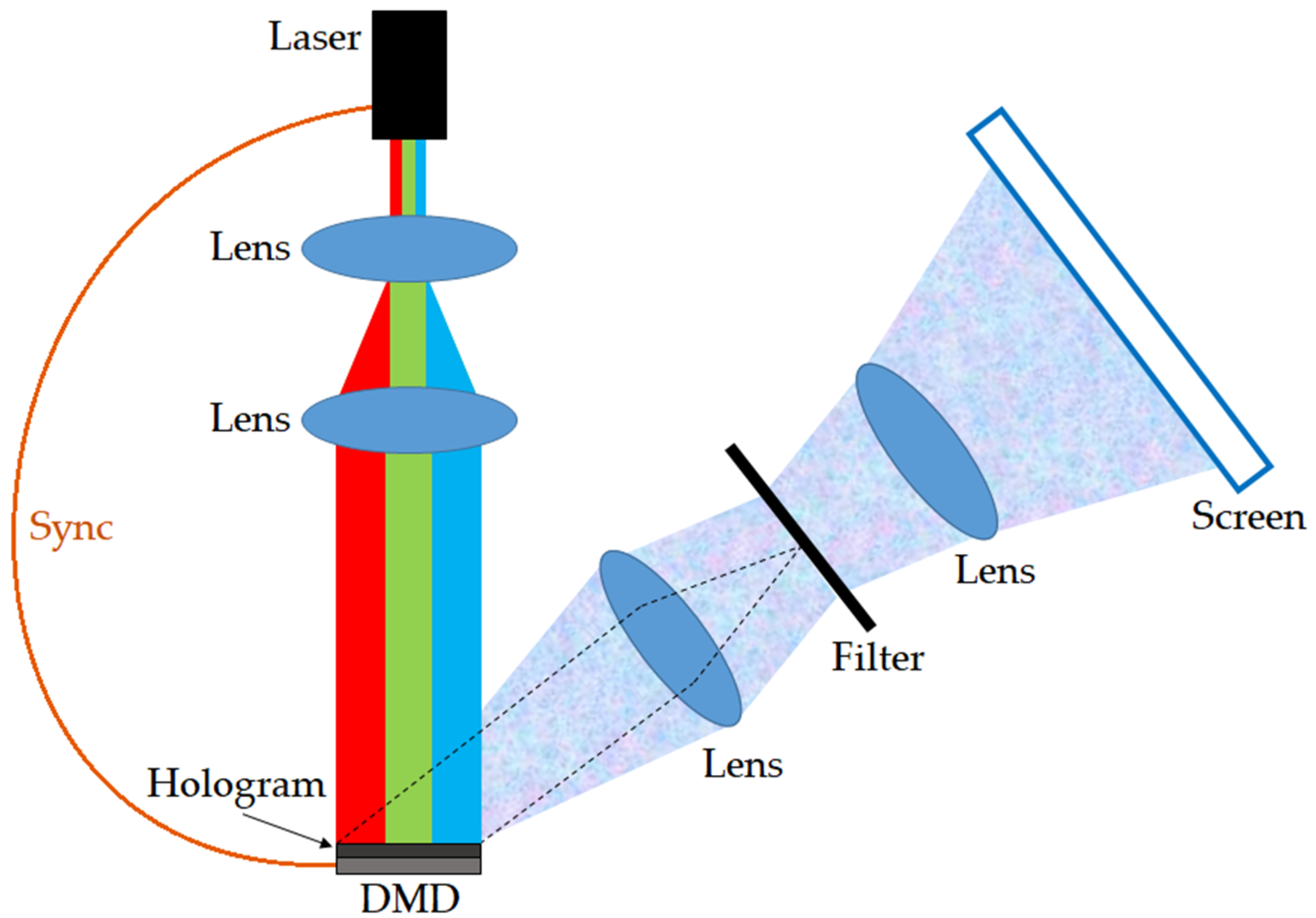
2. Methods
2.1. Multi-Random Phase Method
2.2. Pixel Separation Method
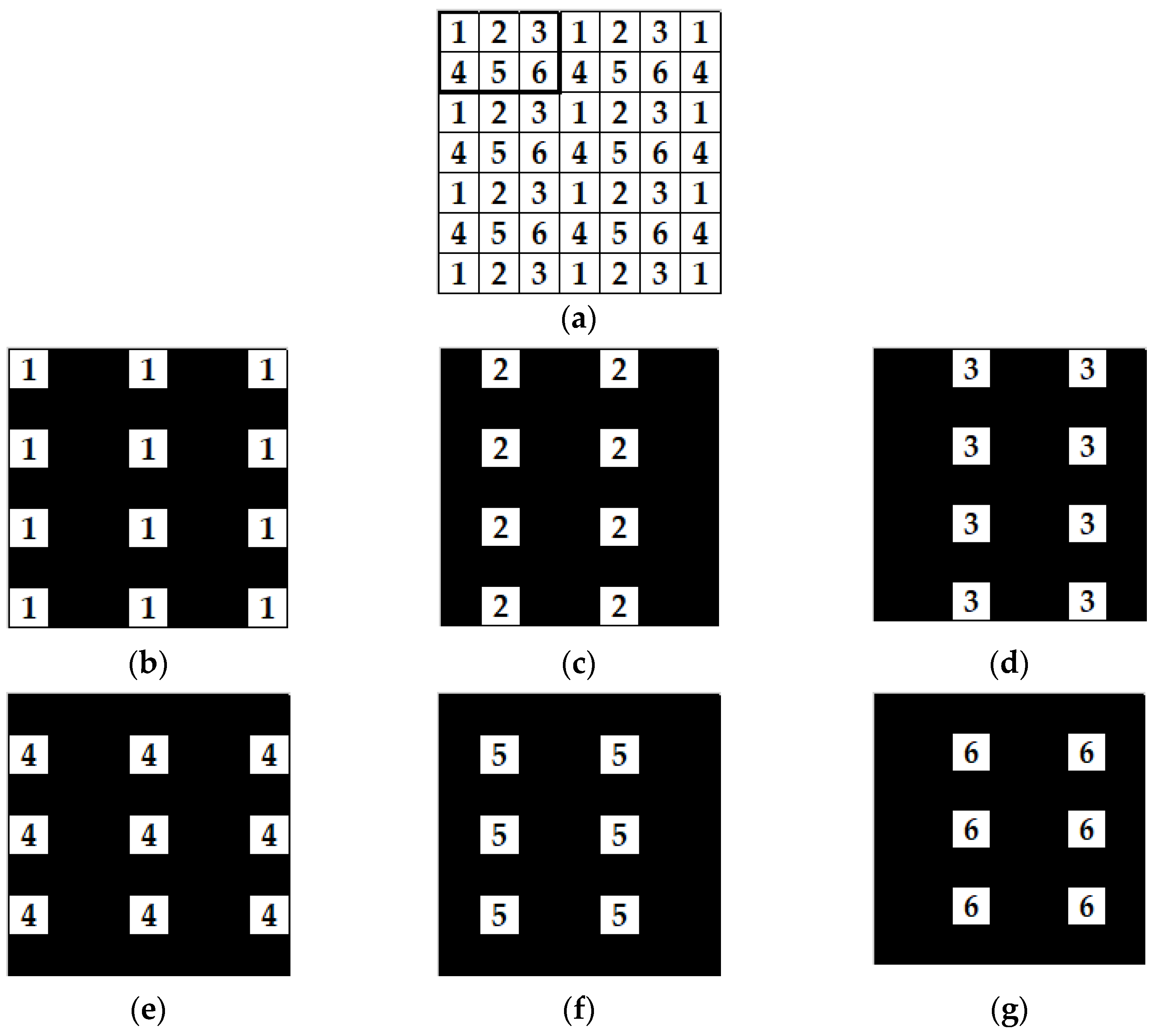
2.3. Proposed Method: Time-Division Reconstruction Method
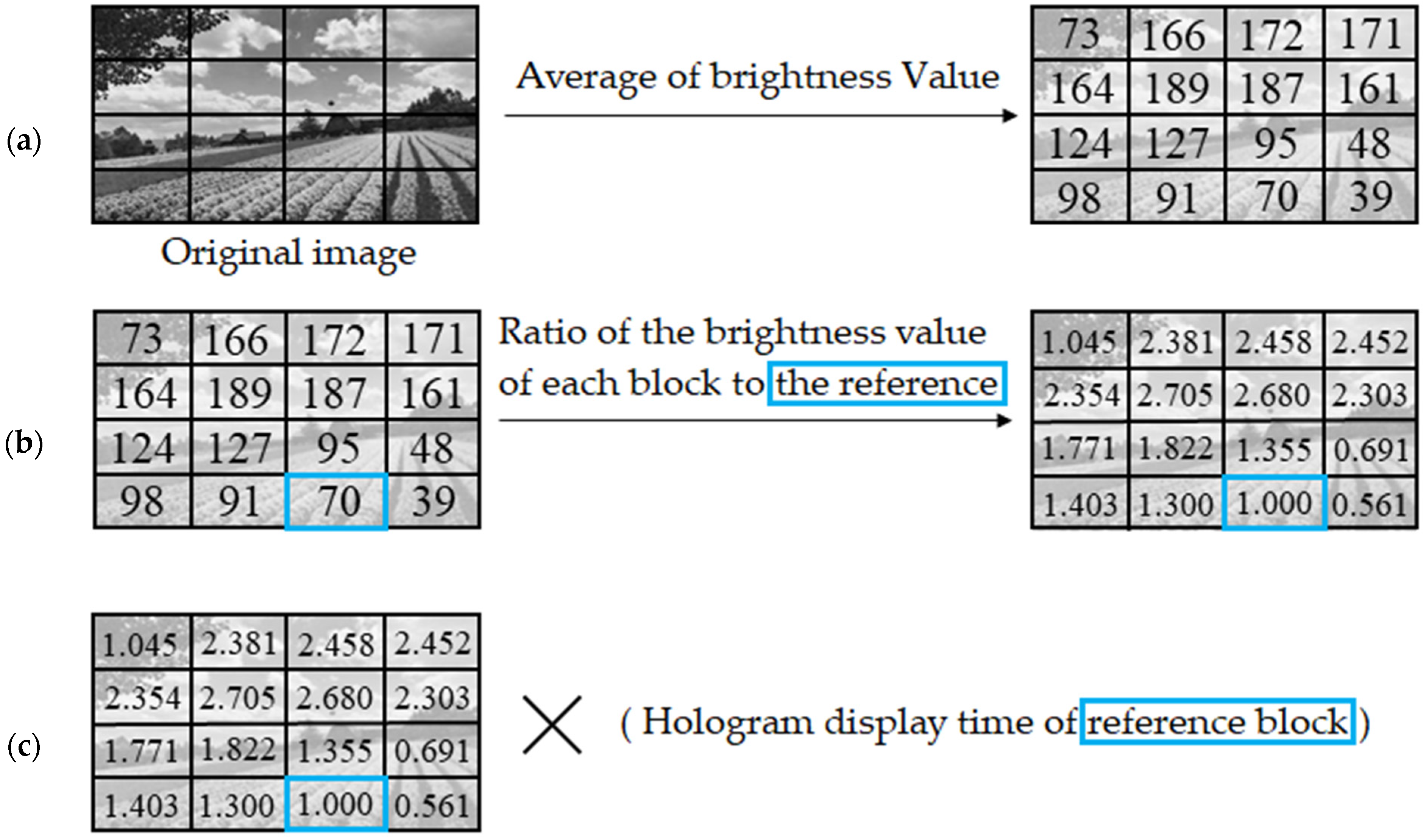
2.4. Uneven Color Correction
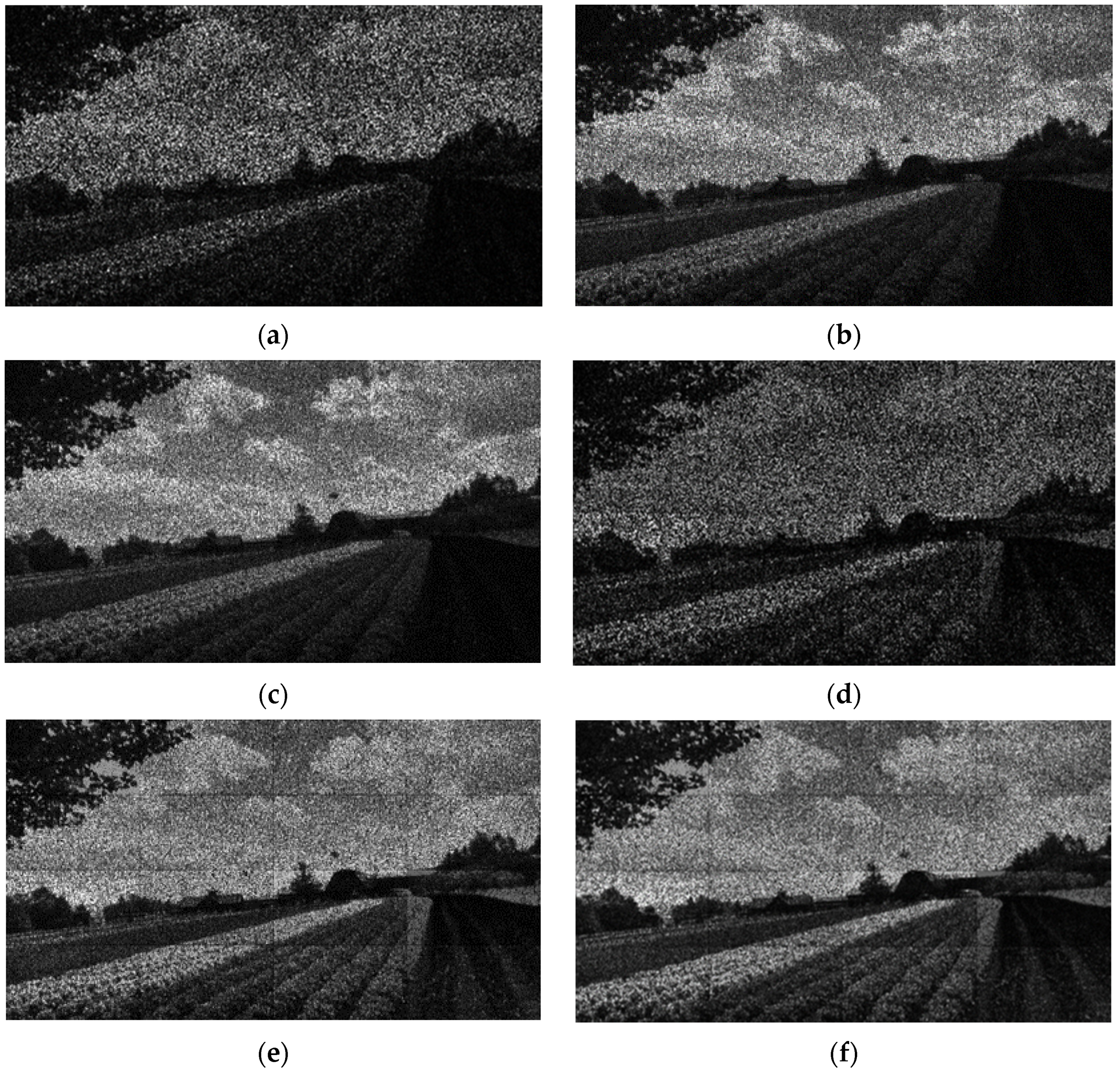
3. Results
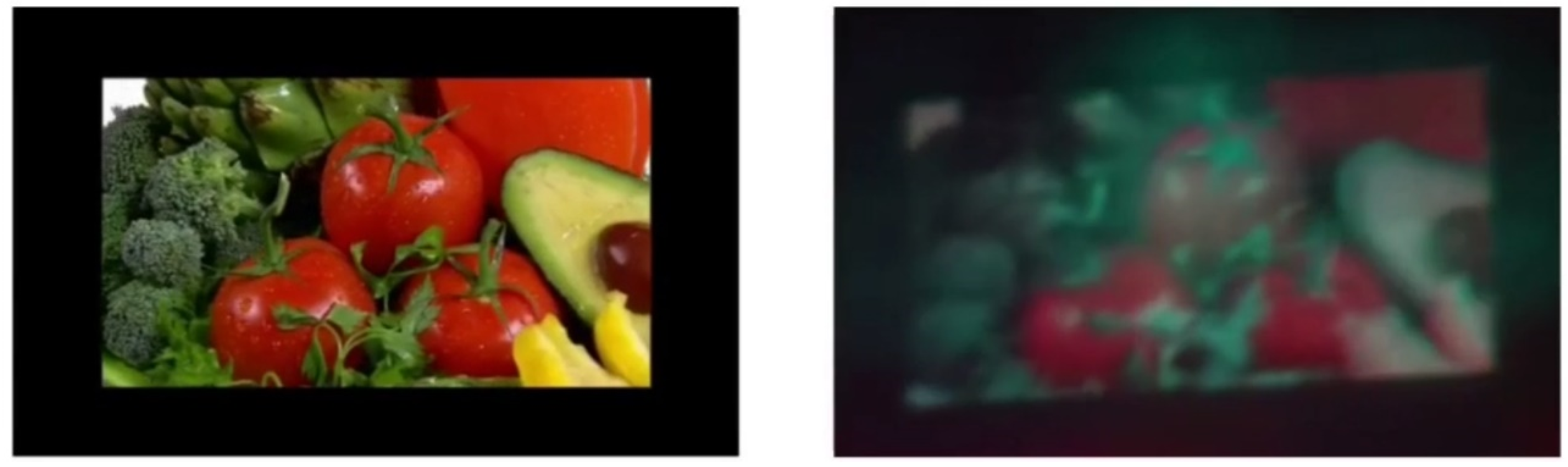
3.1. Simulation Results
3.2. Optical Reconstruction Results
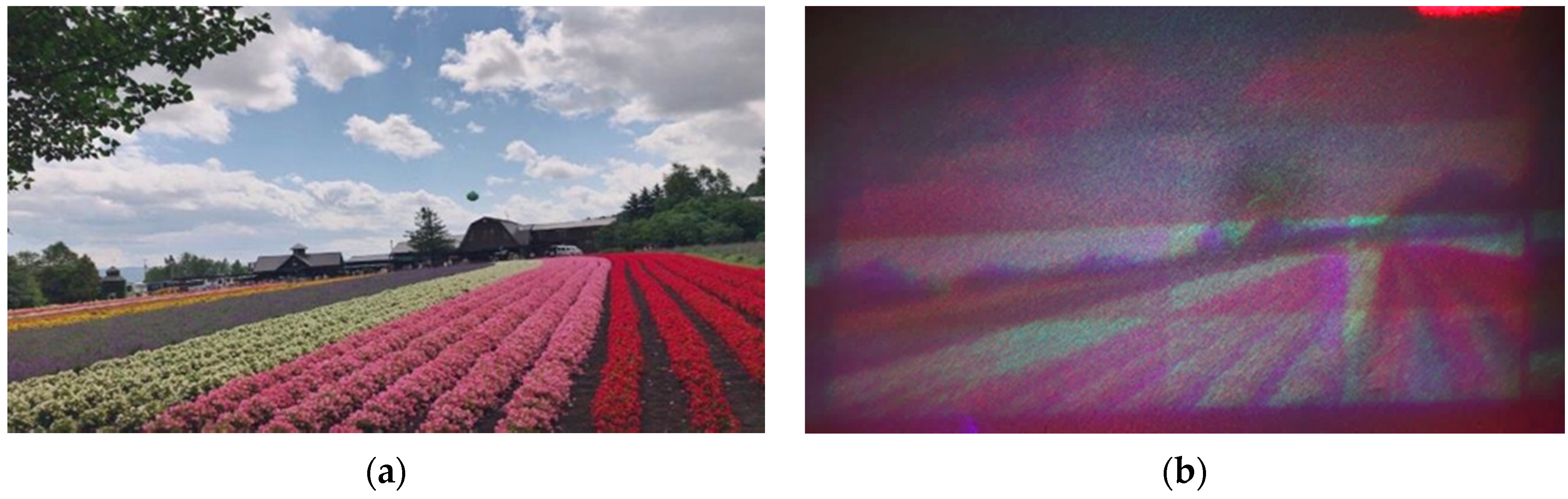
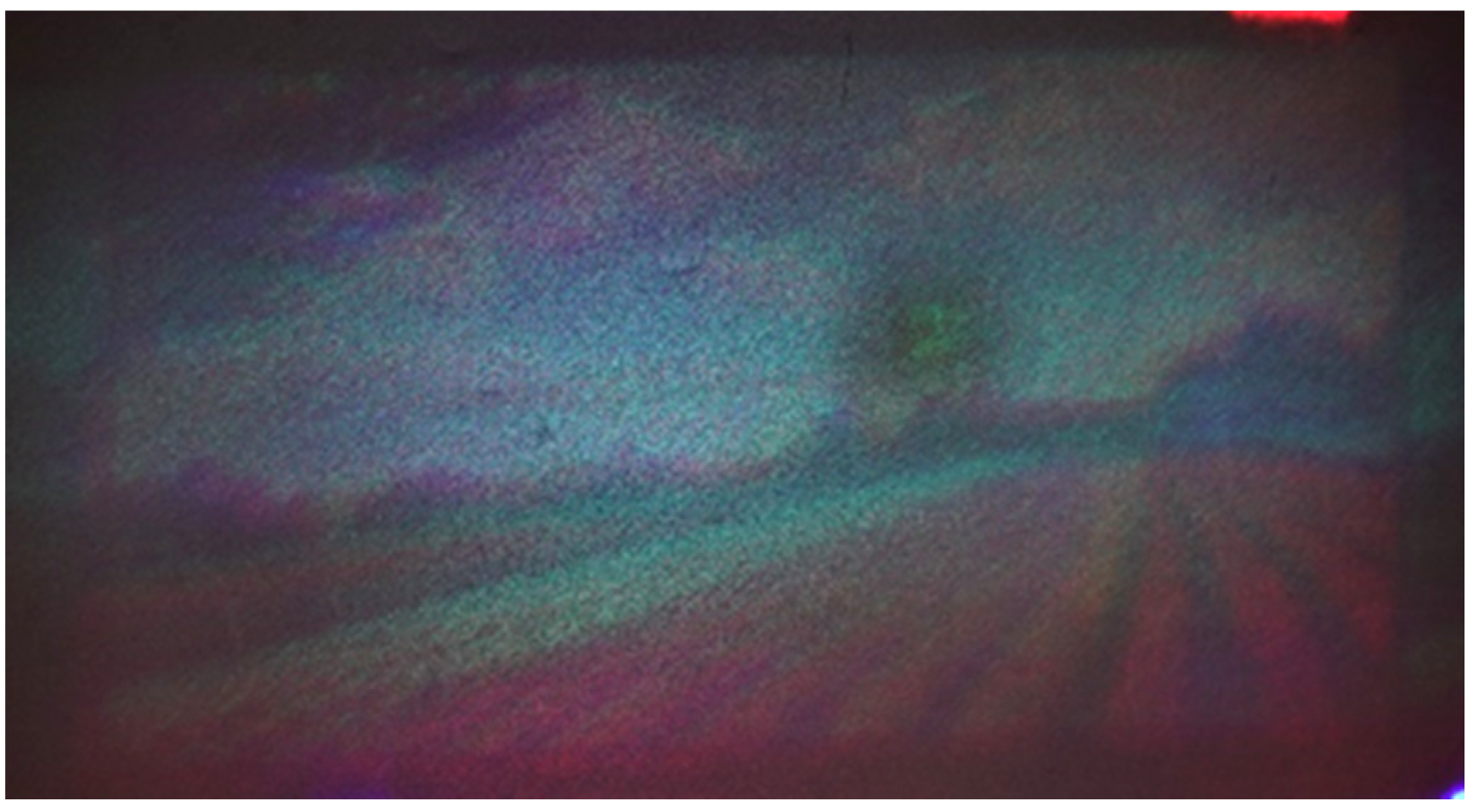
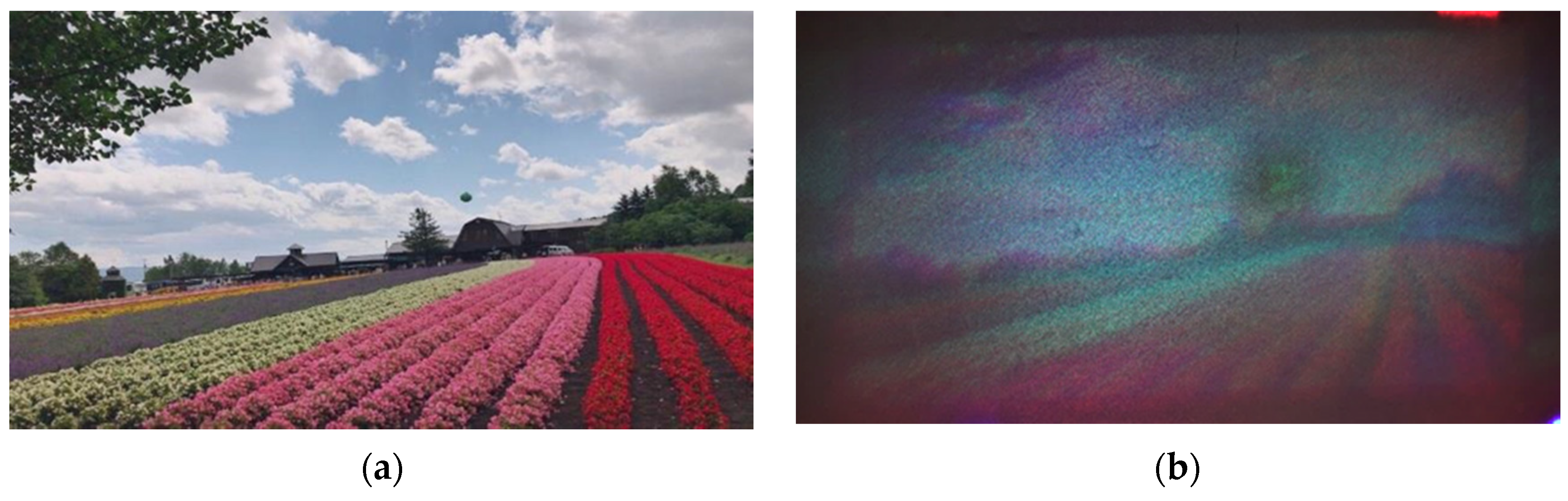
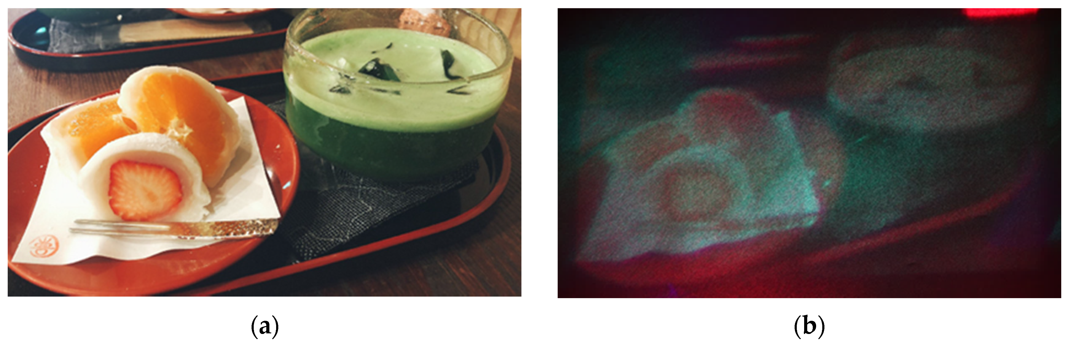
3.3. Full-Color Reconstruction Results
4. Conclusions
Supplementary Materials
Author Contributions
Funding
Institutional Review Board Statement
Informed Consent Statement
Data Availability Statement
Acknowledgments
Conflicts of Interest
References
- Tsang, P.W.M.; Poon, T. Review on the State-of-the-Art Technologies for Acquisition and Display of Digital Holograms. IEEE Trans. Ind. Inform. 2016, 12, 886–901. [Google Scholar] [CrossRef]
- Yaraş, F.; Kang, H.; Onural, L. State of the Art in Holographic Displays: A Survey. J. Disp. Technol. 2010, 6, 443–454. [Google Scholar] [CrossRef]
- Olivier, R.; Kettunen, V.; Herzig, H.P. Review of iterative Fourier-transform algorithms for beam shaping applications. Opt. Eng. 2004, 43, 2549–2556. [Google Scholar]
- Buckley, E. Holographic Laser Projection. J. Disp. Tech. 2010, 99, 1–6. [Google Scholar] [CrossRef]
- Shimobaba, T.; Kakue, T.; Ito, T. Real-time and low speckle holographic projection. In Proceedings of the 2015 IEEE 13th International Conference on Industrial Informatics (INDIN), Cambridge, UK, 22–24 July 2015. [Google Scholar]
- Nagahama, Y.; Shimobaba, T.; Kawashima, T.; Kakue, T.; Ito, T. Holographic multi-projection using the random phase-free method. Appl. Opt. 2016, 55, 1118–1123. [Google Scholar] [CrossRef] [PubMed]
- Shimobaba, T.; Makowski, M.; Kakue, T.; Oikawa, M.; Okada, N.; Endo, Y.; Hirayama, R.; Ito, T. Lensless zoomable holographic projection using scaled Fresnel diffraction. Opt. Express 2013, 21, 25285–25290. [Google Scholar] [CrossRef] [PubMed]
- Bleha, W.P., Jr.; Lei, L.A. Advances in Liquid Crystal on Silicon (LCOS) spatial light modulator technology. Int. Soc. Opt. Photonics 2013, 8736, 87360A. [Google Scholar]
- Abbasi, H.; Zarei, T.; Farahani, N.J.; Rad, A.G. Studying the Recent Improvements in Holograms for Three-Dimensional Display. Int. J. Opt. 2014, 519012, 1–7. [Google Scholar] [CrossRef] [Green Version]
- Amako, J.; Miura, H.; Sonehara, T. Speckle-noise reduction on kinoform reconstruction using a phase-only spatial light modulator. Appl. Opt. 1995, 34, 3165–3171. [Google Scholar] [CrossRef]
- Makowski, M. Minimized speckle noise in lens-less holographic projection by pixel separation. Opt. Express 2013, 21, 29205–29216. [Google Scholar] [CrossRef] [PubMed]
- Tsang, P.W.M.; Chow, Y.T.; Poon, T.-C. Generation of patterned-phase-only holograms (PPOHs). Opt. Express 2017, 25, 9088–9093. [Google Scholar] [CrossRef]
- Shimobaba, T.; Ito, T. Random phase-free computer-generated hologram. Opt. Express 2015, 23, 9549–9554. [Google Scholar] [CrossRef]
- Shimobaba, T.; Kakue, T.; Endo, Y.; Hirayama, R.; Hiyama, D.; Hasegawa, S.; Nagahama, Y.; Sano, M.; Oikawa, M.; Sugie, T.; et al. Random phase-free kinoform for large objects. Opt. Express 2015, 23, 17269–17274. [Google Scholar] [CrossRef] [Green Version]
- Makowski, M.; Shimobaba, T.; Ito, T. Increased depth of focus in random-phase-free holographic projection. Chin. Opt. Lett. 2016, 14, 120901. [Google Scholar] [CrossRef]
- Makowski, M.; Sypek, M.; Kolodziejczyk, A.; Mikula, G. Three-plane phase-only computer hologram generated with iterative Fresnel algorithm. Opt. Eng. 2005, 44, 125805. [Google Scholar] [CrossRef]
- Chen, L.; Tian, S.; Zhang, H.; Cao, L.; Jin, G. Phase hologram optimization with bandwidth constraint strategy for speckle-free optical reconstruction. Opt. Express 2021, 29, 11645–11663. [Google Scholar] [CrossRef]
- Chakravarthula, P.; Peng, Y.; Kollin, J.; Fuchs, H.; Heide, F. Wirtinger holography for near-eye displays. ACM Trans. Graph. 2019, 38, 1–13. [Google Scholar] [CrossRef] [Green Version]
- Muffoletto, R.P.; Tyler, J.M.; Tohline, J.E. Shifted Fresnel diffraction for computational holography. Opt. Express 2007, 15, 5631–5640. [Google Scholar] [CrossRef] [PubMed]
- Shimobaba, T.; Kakue, T.; Okada, N.; Oikawa, M.; Yamaguchi, Y.; Ito, T. Aliasing-reduced Fresnel diffraction with scale and shift operations. J. Opt. 2013, 15, 075405. [Google Scholar] [CrossRef] [Green Version]
- Shimobaba, T.; Ito, T. A color holographic reconstruction system by time division multiplexing with reference lights of laser. Opt. Rev. 2003, 10, 339–341. [Google Scholar] [CrossRef]
- Shimobaba, T.; Weng, J.; Sakurai, T.; Okada, N.; Nishitsuji, T.; Takada, N.; Shiraki, A.; Masuda, N.; Ito, T. Computational waveoptics library for C++: CWO++ library. Comput. Phys. Commun. 2012, 183, 1124–1138. [Google Scholar] [CrossRef] [Green Version]


| Parameters | Values |
|---|---|
| CGH resolution | 1920 × 1080 pixels |
| CGH pixel pitch | 7.56 µm |
| Wavelength of RGB lasers | Red: 632 nm, Green: 520 nm, Blue: 450 nm |
| Projection distance | 3.0 m |
| Methods | Summary | ||
|---|---|---|---|
| Comparison Methods | (a) | Pixel pitch expansion | Used the method of in [7]. The pixel pitch of the original image is four times (30.24 µm) to enlarge the reconstructed image. The pixel pitch should not exceed the Nyquist frequency. |
| (b) | Pixel pitch expansion + Multi-random phase | This combines (a) above with the multi-random phase method [10]. Six CGHs with different random phases are projected. | |
| (c) | Pixel pitch expansion + Pixel separation | This combines method (a) with the pixel separation method [11] and projects six CGHs with different separation images. | |
| Proposed Methods | (d) | Time-division reconstruction + Uneven color correction | A method that combines time-division reconstruction method with uneven color correction. Up-samples the original image to four times its resolution (7680 × 4320 pixels). Divide the original image horizontally and vertically into 4 × 4 blocks. |
| (e) | Time-division reconstruction + Uneven color correction + Multi-random phase | This combines method (d) with the multi-random phase method [10]. Six CGHs with different random phases were projected onto each block. | |
| (f) | Time-division reconstruction + Uneven color correction + Pixel separation | This combines method (d) with the pixel separation method [11] and projects six CGHs with different separation images. |
| Methods | MSE | ||
|---|---|---|---|
| Comparison Method | (a) | Pixel pitch expansion | 9648.8 |
| (b) | Pixel pitch expansion + Multi-random phase | 4509.9 | |
| (c) | Pixel pitch expansion + Pixel separation | 4316.4 | |
| Proposed Method | (d) | Time-division reconstruction + Uneven color correction | 9640.3 |
| (e) | Time-division reconstruction + Uneven color correction + Multi-random phase | 4107.0 | |
| (f) | Time-division reconstruction + Uneven color correction + Pixel separation | 4085.6 |
Publisher’s Note: MDPI stays neutral with regard to jurisdictional claims in published maps and institutional affiliations. |
© 2021 by the authors. Licensee MDPI, Basel, Switzerland. This article is an open access article distributed under the terms and conditions of the Creative Commons Attribution (CC BY) license (https://creativecommons.org/licenses/by/4.0/).
Share and Cite
Takahashi, T.; Shimobaba, T.; Kakue, T.; Ito, T. Time-Division Color Holographic Projection in Large Size Using a Digital Micromirror Device. Appl. Sci. 2021, 11, 6277. https://doi.org/10.3390/app11146277
Takahashi T, Shimobaba T, Kakue T, Ito T. Time-Division Color Holographic Projection in Large Size Using a Digital Micromirror Device. Applied Sciences. 2021; 11(14):6277. https://doi.org/10.3390/app11146277
Chicago/Turabian StyleTakahashi, Takayuki, Tomoyoshi Shimobaba, Takashi Kakue, and Tomoyoshi Ito. 2021. "Time-Division Color Holographic Projection in Large Size Using a Digital Micromirror Device" Applied Sciences 11, no. 14: 6277. https://doi.org/10.3390/app11146277
APA StyleTakahashi, T., Shimobaba, T., Kakue, T., & Ito, T. (2021). Time-Division Color Holographic Projection in Large Size Using a Digital Micromirror Device. Applied Sciences, 11(14), 6277. https://doi.org/10.3390/app11146277