1. Introduction
Achievement of the stability of an excavation is the main design objective in order to avoid failure. In such a case, soldier piles are frequently used to support structures in geotechnical engineering applications that are constructed to resist lateral earth pressures caused by vertical excavation works or to restrain the movement of inclined ground. The ease and speed of construction works of soldier piles increase their preferability, and no advanced exclusive techniques are required for structuring [
1]. In the design process of all retaining structures, it is a basic application to determine the lateral earth pressures that are affecting as active and passive for the acquirement of resisting and destabilizing forces. It will be proper to say that the active lateral earth pressure is the major effective force that is leading the structure to fail. The passive lateral earth pressure can be defined as the resisting force to failure occurrence. These lateral pressures and their distribution through the depth can be changed depending on the nature of the surrounding soil profile and environmental conditions [
2]. Therefore, it is necessary to obtain the soil characterization of the site and to predict the geotechnical properties of related soil layers accurately to acquire a stable system and sustainable usage life. Following in the development process of lateral earth pressure theories; several theoretical, experimental, and empirical studies are conducted to determine the generation of lateral pressures through the pile depth depending on the soil properties, depth of excavation, and environmental conditions [
3,
4,
5,
6,
7]. In most of these studies, the limit equilibrium method is selected as a premise prediction tool to design soldier pile retaining walls [
8,
9,
10,
11,
12,
13], and it is typically proposed that the stability of cantilever soldier piles can be supplied uttermost approximately within 4–8 m excavations [
14,
15]. Deeper excavation works commonly necessitate external supports such as wales and struts [
6]. Nevertheless, strutted excavations seems not to be an economical solution when an open-cut excavation is done that is necessitated for a large area. At this stage, the installation and cancellation works are conducted for struts, while the construction process reduces the construction efficiency [
5]. Thus, if circumstances allow, it is mostly preferred to solve lateral earth pressure problems with the use of cantilever soldier piles. Although there are differences between their structures, soldier pile retaining walls are sometimes being designed similar to sheet pile walls [
4,
5,
16,
17]. It is supposed as a sheet pile wall to ensure both force and moment equilibrium concurrently with the use of two equations. These equations when coupled can be written with the functions of the embedment depth and the location of the pivot point where it is assumed that the wall rotates under the effect of unbalanced forces [
2,
16]. In addition to this mentioned method, another perspective is presented in the related literature. The soldier piles can be assumed to behave similar to beams on elastic soil, and the piles are considered to locate tangent [
5,
18,
19,
20,
21,
22]. However, it has to be noted that all these mentioned methods can give conservative results by not considering the deformation profile of the soil, which is playing a key role both in design and sustainable usage term. Recently, according to the ignorance of deformation determination, advanced methods based on new computer technologies are preferred to be used at the geotechnical design stage to enable faster and more accurate results [
1,
23,
24,
25,
26,
27]. From this point of view, most of the geotechnical engineering software that are used to model the cantilever soldier piles only depends on the calculation of lateral balance through the wall system according to the defined cross-sections. The well-known pre-design methods [
14] that are mostly based on experience are used to model the pile wall system to check against the stability considerations. The results of the conducted analyses are also evaluated dependent on the stability and deformation boundaries of the geotechnical perspective. This condition means that no predictions about the dimensions of the pile system are included in the logic of the used software within the theme of geotechnical modeling. According to this situation, back analysis has to be conducted to obtain the applicable dimensions of the retaining structure with ensuring certain safety degree and deformation criteria. Besides, conducting stability analyses of an excavation case can contribute to obtaining the embedment depth and diameter of the cantilever soldier pile wall, but it is also necessary to calculate the bending moment and shear force of the structure to design the reinforced concrete columns. In addition to all these, in order to complete the structural design process, the number and diameter of the reinforcement required in reinforced concrete columns should also be determined. Most of the currently used software cannot ensure procuring the results of both geotechnical and structural design; also, the literature studies about this whole design process including both geotechnical and structural design process are missing. In order to overcome this absence in the present study, the design of the cantilever soldier piles has been done by the use of the harmony search algorithm with Matlab software. It is aimed to show the novelty of the use of optimization techniques to design a cantilever soldier pile system dependent on the selection of dimensions with the consideration process of geotechnical stability and structural requirements simultaneously with the cost efficiency. Besides, multivariate parametrical analyses are conducted, and the results are obtained to see the effects of the prediction of soil geotechnical properties such as the shear strength, unit weight, and coefficient of soil reaction on design. Environmental effects such as external loading and the change of excavation depth are also investigated. The results are interpreted by the determination of the cost of construction of a pile, the soldier pile diameter, and the embedment depth. Besides, discussions are performed to compare the optimization results with the geotechnical finite element method-based software analysis results to assess whether the proposed design process is satisfactory.
2. Design and Methodology
The design of retaining structures consists of the integrated analysis of two different fields such as geotechnical and structural engineering, as before mentioned. In addition to these design issues, the cost of the structural system is the identifier parameter of the design process to select the applicable type. However, it is hard to acquire both the safety and economy simultaneously saving time and labor by the usage of traditional design methods [
28]. Therefore, in recent studies, the techniques that allow saving time and cost have been used in the design process of retaining structures. In this regard, Weng et al. used optimization algorithms with a single objective optimistic model using the m-method of piles in a row design and discussed the wall displacement via cost [
29]. Xu and Qian used genetic algorithm to optimize the design parameters of the retaining pile system [
30]. In a similar vein, within the present study, optimization of the cantilever soldier pile retaining walls has been investigated with the use of harmony search algorithm but differentiated from the reference studies, the design rules of the pile system is defined with the beams on elastic soil assumption. Besides this, the present study is differentiated from other studies by the type of selected design variants (project necessities, soil properties, and environmental conditions), by used design rules (beam on elastic soil assumption), and by the applied comparison procedure (comparisons with a well-known commercial geotechnical analysis software). Therefore, the design procedures of cantilever soldier piles based on the mentioned method are described step by step to detail all these differences.
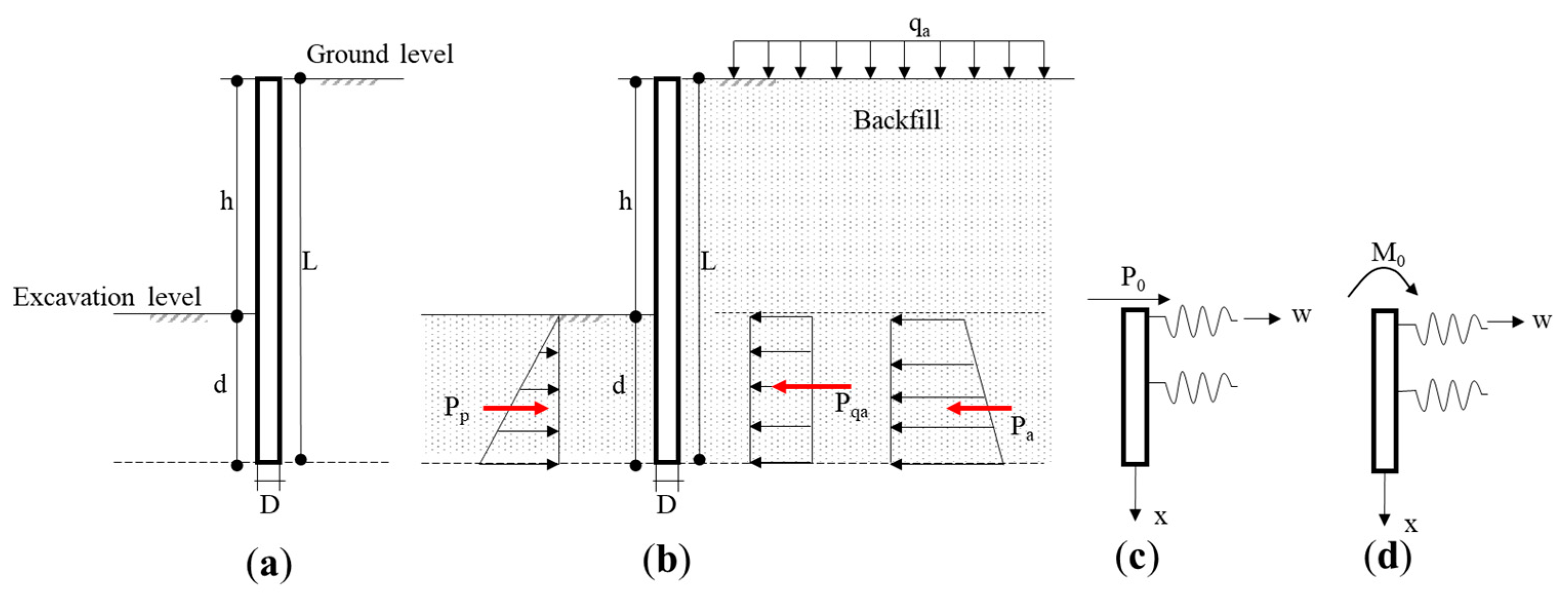
The cross-section of a simple cantilever soldier pile wall is given in
Figure 1a. In
Figure 1a, the symbols
h, d, L, and
D represent the excavation depth, embedment depth, and total length of the pile and the diameter of the pile, respectively. The stability of soldier pile walls relies upon the mobilization of earth pressures on both sides of the wall stem [
8,
9]. Active and passive stresses which are generated according to this earth pressures are shown in
Figure 1b according to the beam on elastic soil assumption. Rankine Earth Pressure Theory is used to calculate lateral earth coefficients.
qa describes the external load that is affecting the soldier pile at the active side of the wall.
qa is converted to lateral load (
Pqa) by the use of active lateral earth coefficient of natural soil conditions.
Pa and
Pp define the lateral soil reaction forces of the active and passive side, respectively.
Within this paper, cantilever soldier piles are assumed to behave similar to beams on elastic soil and the piles are considered to constitute a continuous wall system by locating tangent. Depending on the continuous elastic support assumption, the soil is described by an elastic continuum [
18,
19,
20,
21], and the reaction of the soil at a specified section of a pile is only dependent on the deformation of that part and not on the deflections of pile above and below it [
20,
22,
31]. For this reason, it is assumed that the calculation of the embedment depth and pivot point location is only dependent on the equilibrium of forces, which are activated through the penetrated part of the pile in the soil. The main important feature supplied by using soil as a continuum medium is that input variables can be directly related to measurable and realistic soil properties such as the stiffness and strength of the material [
5]. The representative parameters of the flexural rigidity and characteristic length of the pile are
EI and
l0, respectively. In the case of an acting single horizontal force or moment at the edge of the beam (
Figure 1c), with the use of the constant and variable coefficient of soil reaction through depth (
KS), the change of deflection, rotation, bending moment, and shear force for different depths can be calculated by Equations (1)–(4).
The characteristic length of the pile is described by
l0; it can be calculated by the use of Equation (5) for the constant coefficient of reaction, and it can be calculated by using Equation (6) for a linear change of the coefficient of reaction through the depth. The embedment depth of the pile can be determined with the “
πl0” equation for soldier piles to behave similar to beam-supported elastic soil [
32]. The total length of the pile can be calculated by the sum of excavation depth and embedment depth.
Depending on the above-mentioned assumption to design cantilever soldier pile walls, the first step of the present study is decided and multivariate parametric analyses are conducted to obtain the effects of design parameters. This method is applied to numeric analyses that are carried out by using Matlab software, the harmony search algorithm (HS), and the effects of the change of excavation depth, shear strength angle, and unit weight of soil, external loading condition, and coefficient of soil reaction are investigated. The harmony search algorithm was developed by Geem et al. in 2005 as a meta-heuristic algorithm that is based on the natural musical performance process to search for a perfect state of harmony similar to during jazz improvisation [
33]. The Jazz improvisation investigates to obtain musically pleasing harmony as a perfect state that can be determined by an aesthetic standard, and the optimization process researches to acquire a global solution as a perfect state that can be calculated by an objective function [
34]. The HS algorithm process can be arranged with five steps.
Step 1: A harmony memory is initialized [
35]. The definition of design constants, upper and lower limits of design variables, maximum iteration number, and the values of algorithm-specific parameters are done. Three special parameters are used for HS that are named harmony memory size (HMS), harmony memory consideration rate (HMCR), and the t pitch adjustment rate (PAR), respectively.
Step 2: A new harmony is improvised [
35] from the creation of a harmony vector with the generation of a random value (
rnd(0,1)) within a range. The upper (upper limit (
Xi,max) and lower limits (
Xi,min)) are defined for each design variable (
Xi) (Equation (7)). With the usage of the constants and design variables of the problem, the motion equation is solved; following, the solution of the objective function is procured, and the result of this objective function is stored in harmony vector.
This process is repetitive, as much as the size of the harmony memory and every harmony vector is stored in a matrix named the initial solution matrix.
Step 3: The iteration process is started, and the New Harmony vector is created. This creation can be done in two ways based on the algorithm rules. It is possible to generate the design variables randomly within the identified upper and lower limits, or a new vector can be activated using a chosen vector (
Xi,old) from the solution matrix (Equation (8)). New (
Xi,new) values are generated randomly by the multiplication difference of design variable limits and the pitch adjusting rate (PAR) while the process is loading. The selection of the proper way to evaluate the new vector is based on the value of HMCR. Correspondingly, the generation of a random value takes place, and if the random value becomes less than the value of HMCR, the first way is selected; otherwise, the second way is applied.
Step 4: Comparison of the new vector with the vectors stored in a solution matrix is done. With regard to the objective function, the existing vector is replaced with a new one if the next vector is better than the existing vector defined in the matrix. If not, the solution matrix is saved in its current form. The better solution is evaluated by the comparison of the value obtained from the objective function, and the minimum one is chosen. The design constraint is also taken into consideration during comparisons. In addition to this, the amounts of violations are controlled, and if the violations of the design constraints exist, the solution with minimum violation is chosen as the best solution.
Step 5: Controlling the stopping criterion. Iterations are continued until the satisfaction of stopping criterion. This criterion can be identified in different ways, and it has been calculated as the maximum number of iterations in the present study.
Three different design parameters were considered to apply the HS algorithm to the cantilever soldier pile problem. The variables are related to the cross-sectional dimensions (
X1) and the reinforcement design of the wall (
X2, X3), and the details of the definitions of variables are given in
Table 1.
The reinforced concrete requirements are defined according to ACI 318-05 code [
36]. The ACI 318 code proposes to use equivalent rectangular compressive stress distribution rather than other stress distributions such as parabolic. With the use of equivalent compressive stress distribution, the moment capacity of the cross-section of the cantilever soldier pile can be determined. The critical section of the pile is only checked for reinforcement design. The flexural moment (
Mu), the shear force (
Vu), the spacing between two bars (
S), the area of reinforcing bars (
As), and the diameter of bars (
db) are defined. National and international pre-design guidelines are used to identify the lower and upper limits of design constraints. The design constraints on strength and dimensions are given in
Table 2.
The supposed objective function of the design includes the unit cost of concrete
Cc, volume of concrete
Vc, unit cost of reinforcing bars
Cs, the unit weight of reinforcing bars
Ws items. The minimum cost of the cantilever soldier pile walls can be determined mathematically by the use of Equation (9).
For the second step of the study, numerical analyses are conducted by a well-known commercial geotechnical finite element method based software Plaxis 2D-Version 2020. The aim of the numerical analysis is to compare the optimization results to know if the envisaged dimensions are proper to ensure adequate stability and limited deformation conditions. Reference cases are selected to control the accuracy of optimization results. The fictionalized reference projects are modeled with the finite element software by 15 node triangular elements with plain strain conditions. The sandy soil profile is modeled with an elastic–perfect plastic material model Mohr Coulomb with a single layer and the cantilever soldier pile is modeled with embedded beam row elements. It is assumed that the ground water level is deep and far from the ground surface. The diameter and length values of the embedded beam row are changed in relation with optimization results for every analysis performed by the use of finite element software. The element distribution mesh used for analysis is defined with fine sensitivity. Phases of the numerical analysis are identified as an actual construction process that is beginning from the installation process of the pile and ended after reaching the envisaged excavation depth. The calculation type is selected as static and plastic; then, the staged construction loading type is assumed, and drained conditions are used. Following, safety analysis is performed with the calculation of global safety factor by means of the strength reduction method. The output of the numerical analysis is arranged to obtain the maximum moment, shear force, factor of the safety value, and the location of the pivot point. Consequently, these mentioned values are compared with the results of the optimization analysis for verification.
3. Parametrical Analyses
In order to investigate the cost and time effective design of cantilever soldier pile retaining wall structures, parametric analysis is presented with the division of two steps. The first step involves the analyses conducted with optimization techniques to show the change effects of design variants, and the second step shows the comparison details of optimization results with finite element software to control the appropriateness of the usage of optimization algorithm to design cantilever soldier piles. For the application of step 1, the HS algorithm is used with the application of beams on elastic soil assumption to evaluate the minimum costs of the cantilever soldier pile retaining walls that are fictionalized according to different project situations in the present study. The design constants and variables of fictionalized cases are given in
Table 3. According to the national and international literature studies, manuals, and technical reports, the depth of excavation is assumed to be between 3 and 12 m [
16,
37,
38,
39]. At the design stage of retaining piles, it is clear that the designers need the soil parameters, especially the unit weight and the shear strength angle, to determine the lateral earth pressures [
3,
4,
5,
6,
7]. It is assumed to embed the pile into a homogenous soil layer that is formed by non-cohesive soils, and the values of the geotechnical parameters are selected from the literature according to the allowable limits [
4,
14]. The unit weight of the soil, the internal friction angle, and the ultimate bearing pressure values are taken as variables, and different cases are fictionalized to compare the effects of soil properties on the design of retaining walls and costs. The unit weight of the soil is defined according to the suggestions of Bowles [
4] and Das [
14]. Bowles defined the unit weights of granular soils due to the relative density and internal friction angle values of specimens. The unit weight values are defined as within 14–18 kN/m
3, 17–20 kN/m
3, and 17–22 kN/m
3 for loose, medium, and dense sand, respectively [
14]. Das defined the unit weight of some typical soils in the natural state. 14.5 kN/m
3 is defined for loose uniform sand, and 18 kN/m
3 is defined for dense uniform sand [
4]. Correspondingly, the unit weight values of sandy soils are assumed to be between 14 and 20 kN/m
3 to perform parametrical analysis. Shear strength angle values are also identified by the use of the suggestions of Bowles and Das. According to the mentioned boundaries, the shear strength angle is selected between 27° and 38° for parametric analyses. Based on the beams on elastic soil assumption, another influencer parameter can be identified as the coefficient of soil reaction to determine the characteristic length of the pile [
14,
32]. It is already a big challenge for geotechnical engineers and researchers to determine the reaction of soil in contact with structure. According to this problem, first investigations are made by Winkler [
40] and a model that assumes the stiffness of the soil, which is considered as the ratio between the contact pressure and the related linear vertical displacement.
This relationship can be defined the coefficient of subgrade reaction,
Ks with MN/m
3 unit. This theory is governed by a linear–elastic model that models the soil behavior as a group of independent springs. This theory is firstly used to perform analysis for rigid plates, but recently, it has been extended to include the determination of the stresses of flexible structures. The coefficient of the soil reaction can be determined by conducting both laboratory (consolidation, triaxial, California bearing ratio tests) and field tests (plate loading test) or using semi-empirical or empirical [
14,
41] equations or selected from tabulated values [
14]. Based on these tabulated values, the coefficient of soil reaction is assumed 200 and 300 MN/m
3 for medium dense and dense sandy soils, respectively [
14]. The external loads that are acting on the retained soil side are assumed to be another variant of the analysis as classified as the environmental conditions. An infinite uniformly distributed load is applied to the top of the wall with the values of 0-5-10-15-20 kPa. The unit cost change of concrete material is also investigated. Five different costs (
$50,
$75,
$100,
$125,
$150) are used to evaluate the material cost effect on the dimensions of the cantilever soldier pile. For the application of step 2, a geotechnical design software is used to model the obtained dimensions of the cantilever soldier pile from optimization analyses.
4. Result and Discussion
Within the discussion part of this study, the data obtained as a result of the application of the HS algorithm were interpreted by expressing them as a function of the pile diameter, pile length, and unit pile cost. In total, 42,000 analyses are conducted to evaluate the relationship between design dimensions and cost. In addition to this, 72 finite element analyses are performed to control the acceptableness of the application of the HS algorithm to design the cantilever soldier pile retaining walls. The first discussions are constituted according to the change of excavation depth. Some reference cases are selected that can be representative of the behavior of all the fictionalized cases to interpret the results.
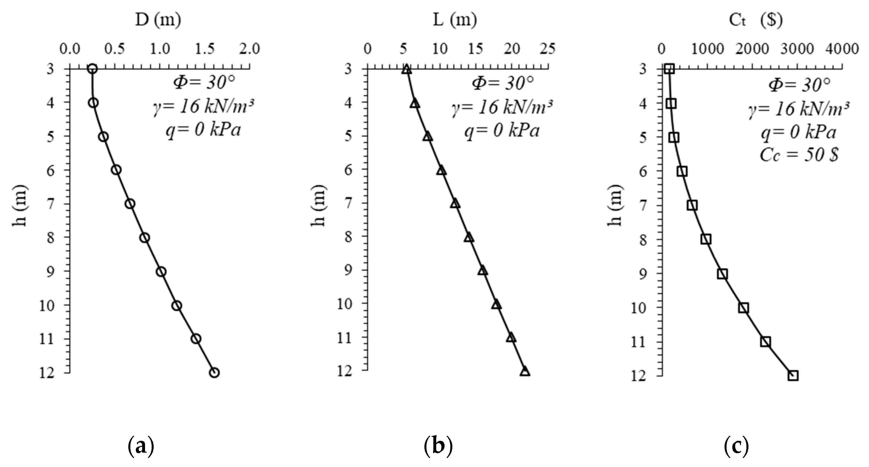
Figure 2 reflects the change of the cantilever soldier pile diameter (a), length (b), and unit cost (c) based on the increase of the excavation depth. The diameter of soldier pile is represented by
D, the length of the pile is
L, and the unit cost of the pile is defined by
Ct symbols. It is assumed to embed the pile into a sandy soil formation that has a shear strength angle of 30°, while the unit weight is 16 kN/m
3, the coefficient of reaction is 200 MN/m
3, and the surcharge load application is absent. The unit cost of the concrete is selected as
$50. It can be seen from
Figure 2 that the increase of the depth of the excavation enlarges the pile diameter and extends the pile length. The unit cost of the cantilever soldier pile is calculated as the indirect function of pile diameter and length; therefore, the cost is raised with the deepening of excavation, as expected. The change of the cantilever soldier pile diameter, length, and cost exhibits same trend as the reference case for all the fictionalized other cases. The increased ratios of all the dependent variables are relatively smaller for shallow excavations, but exhibit a raising tendency based on the increment of depth.
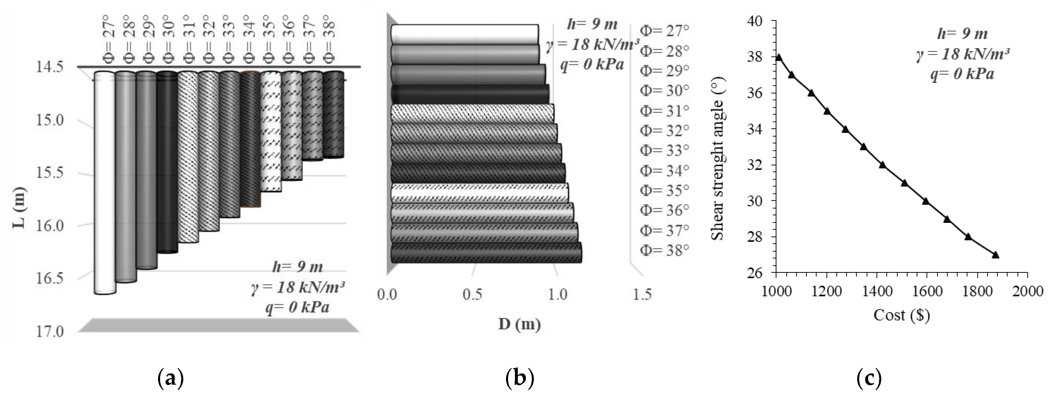
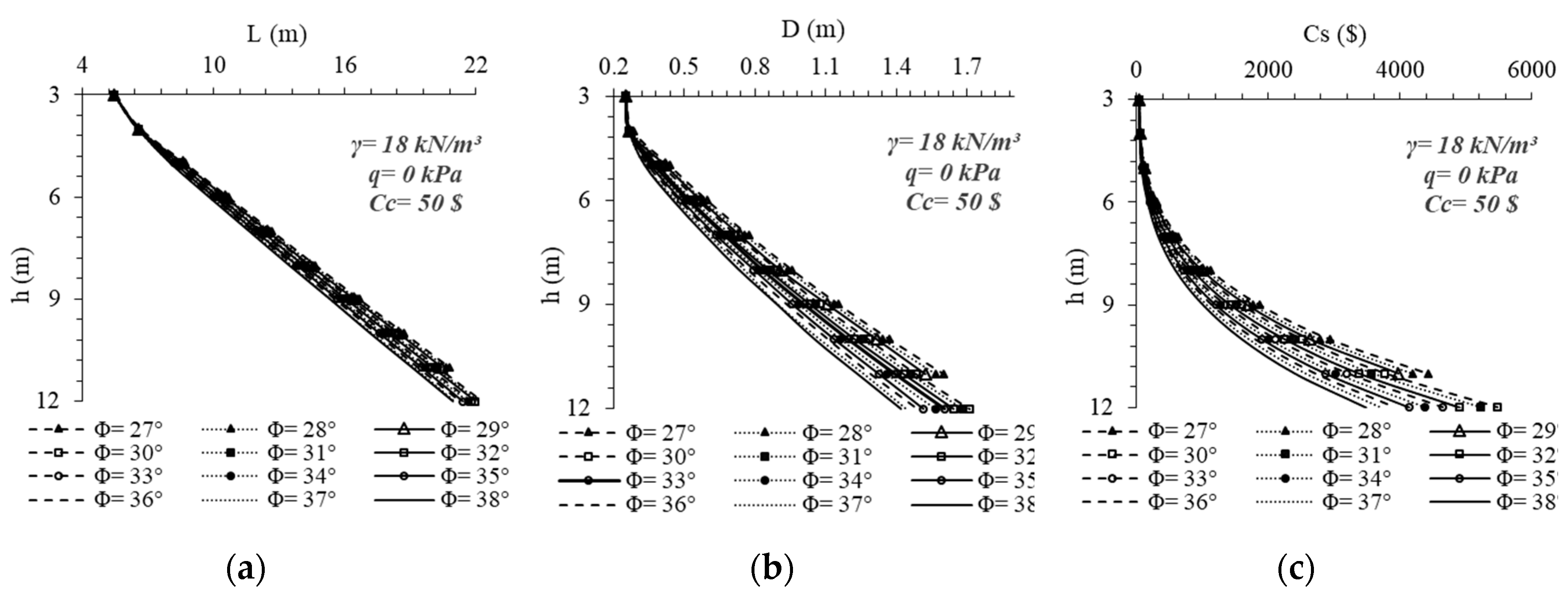
In
Figure 3, the effects of the change of soil strength angle are shown for a specific reference case. The shear strength angle is changed between 27° and 38° to represent the sand formation’s relative density beginning from a loose to a dense state. The depth of excavation is assumed to be constant (
h = 9 m). The surcharge load application is not taken into consideration, and the unit weight of the soil is assumed to be 18 kN/m
3.
Figure 3a represents the change of pile length,
Figure 3b shows the change of pile diameter, and
Figure 3c represents the cost change. The increase of the shear strength angle is directly proportional to the increase of soil strength. Therefore, the rise of the shear strength angle straightens the length of the pile and embedment depth. The relative decrease of pile length is approximately 9% in such a case that the shear strength angle increases from 27° to 38°. Then, the relative decrease of pile diameter is approximately 25% in such a case that the shear strength angle increases from 27° to 38°. Therefore, it can be said that the increase of soil the shear strength angle affects the pile diameter more than the length of the pile. However, in geotechnical applications, generally, a standard diameter is preferred to be used in order to reduce the equipment cost. That’s why if the pile diameter is selected as a constant value for all the excavation depths, the length of the pile will be directly affected by this change more than the change of the internal friction angle. The cost of the unit pile is influenced from the change of the shear strength angle directly. The rise of the strength of the soil leads to decreasing the costs by approximately 46%. In such a case that the soil 44shear strength angle increases from 38° from 27°, the cost of the construction has decreased to
$1010 from
$1873.
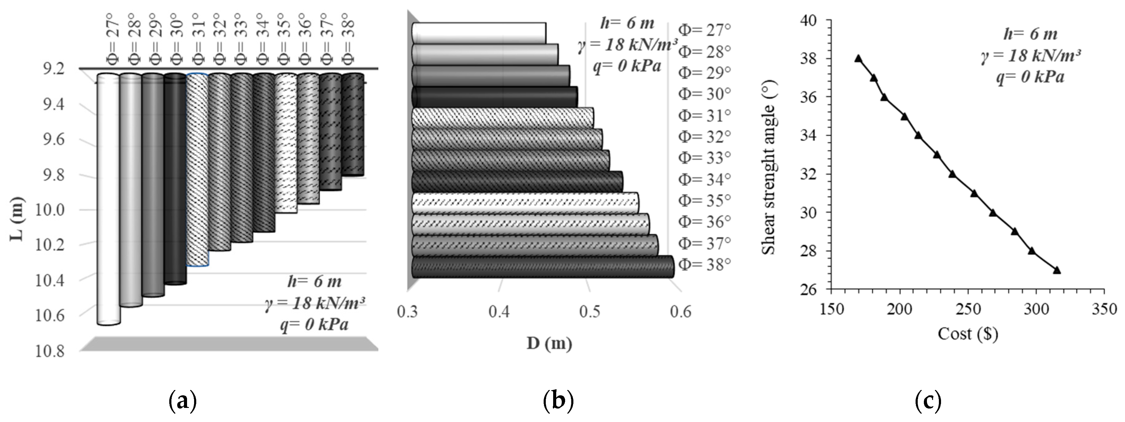
Figure 4 is acquired for the decrease of excavation depth of 6 m. All the other parameters are selected as the same as the case calculated for
Figure 3. The relative decrease of pile length is approximately 9% when the increase of the shear strength angle is from 27° to 38° again for 6 m excavation depth. However, the relative decrease of pile diameter in such a case that the increase of the shear strength angle is from 27° to 38°, is approximately 17%. Similarly with
Figure 3, the rise of the strength of the soil leads to the costs decreasing by approximately 46%. In such a case that the soil shear strength angle increases to 38° from 27°, the cost of the construction has decreased to
$170 from
$315. As a result, the decrease of excavation depth reduces the influence ratio of the change of the shear strength angle. Besides, this reference case is analyzed for 3 m excavation depth, but there is no noticed change of pile length or dimension due to the change of soil shear strength angle.
The change of soil shear strength angle is also evaluated according to the change of excavation length.
Figure 5 is illustrated to understand the change of pile length (a), pile diameter (b), and unit pile cost (c), respectively. It can be directly seen from the comparison of
Figure 5a,b that the change of shear strength angle has a greater effect on the pile diameter than the pile length, especially for deeper excavations. This condition causes encountering unexpected pile lengths for deep excavation projects. In
Figure 5, the main dimension change begins to occur at the depth of 5 m. In the context of this study, according to the worked parameters, it can be a general approach that 5 m excavation depth is assumed to be a limit length of the change of the design. It is a noticeable point that for loose sands that have a shear strength angle between 27° and 30° according to Bowles [
14], the optimization analysis can’t find an appropriate cross-section, which is ensuring both geotechnical and structural design requirements. For this reason, approximately 10 m depth can be assumed to be the upper bound of the applicable excavation with the construction of cantilever soldier piles.
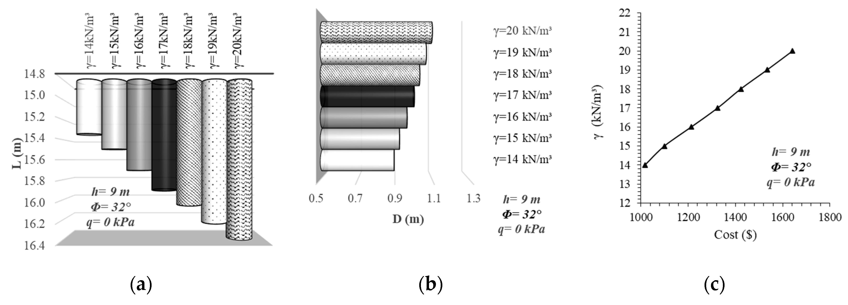
The change of the unit weight of the soil profile is also investigated within the context of present study.
Figure 6 is drawn for 9 m excavation depth to reflect the effect of soil unit weight on the dimension and cost change of the pile. The shear strength angle of the surrounding soil is assumed to be 32°, and surcharge load is not applied. Then, the unit weight of the soil is increased beginning from 14 kN/m
3 to reach 20 kN/m
3 one by one.
Figure 6a shows that the increase ratio of the pile length is approximately 7% for a 6 kN/m
3 increase of unit weight. The increase of unit weight of soil leads to widening the pile diameter by nearly 22%. This condition is based on the computation equations of both active and passive lateral forces. The unit weight is the direct multiplier of these equations. The increase of unit weight affects passive lateral forces more than active lateral forces due to the relative difference between active and passive lateral earth coefficients. Active lateral earth pressure is determined by the Rankine Active Earth Pressure Theory with the
Ka = tan2 (45 − Φ/2) equation, and passive lateral earth pressure is calculated by Rankine Passive Earth Pressure Theory with
Kp = tan2 (45 + Φ/2). The difference of coefficients is directly related to the shear strength angle. However, the shear strength angle is not a direct multiplier of lateral forces. Therefore, it can be said that the change of the unit weight of the soil influences the unit cost of pile more than the change of shear strength angle for the fictionalized cases of this study within the selected parameter limits. The change in the unit cost of the pile can be calculated to be approximately 66% from
Figure 6c. In such a case that the unit weight of soil increases to 20 from 14 kN/m
3, the cost of the construction has increased to
$1642 from
$1017.
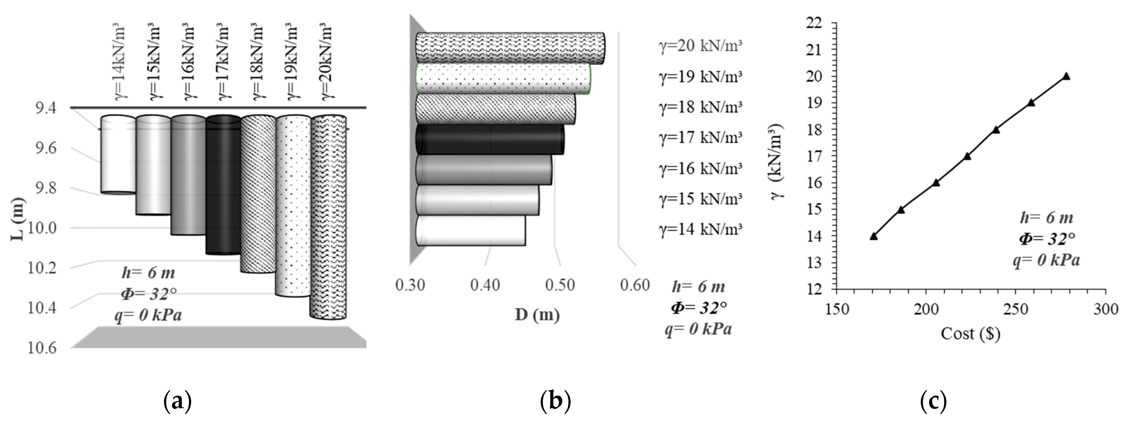
The same reference case with common variables is evaluated in such a case that the excavation depth is assumed to be 6 m.
Figure 7 shows the change of pile length, diameter, and unit cost, respectively. The change of soil unit weight causes obtaining a similar behavior trend as shown in
Figure 6. The increase ratio of the pile length between the lower and upper limit of the envisaged values of unit weight is computed to be 7%. This pile length increment ratio was found to be same for all fictionalized analyses conducted for the evaluation of the unit weight change.
The change of pile diameter is determined to be approximately 20%, and the unit cost change is calculated to be 64% between the upper (
$278) and lower limits of the soil unit weight (
$170). The same reference case is applied to the condition that the excavation depth is 3 m. However, similar to the previous analyses performed in the change of the shear strength angle of soil, the change of the soil unit weight has no effect for relatively smaller excavations. In addition to all of these, in representative charts are given in
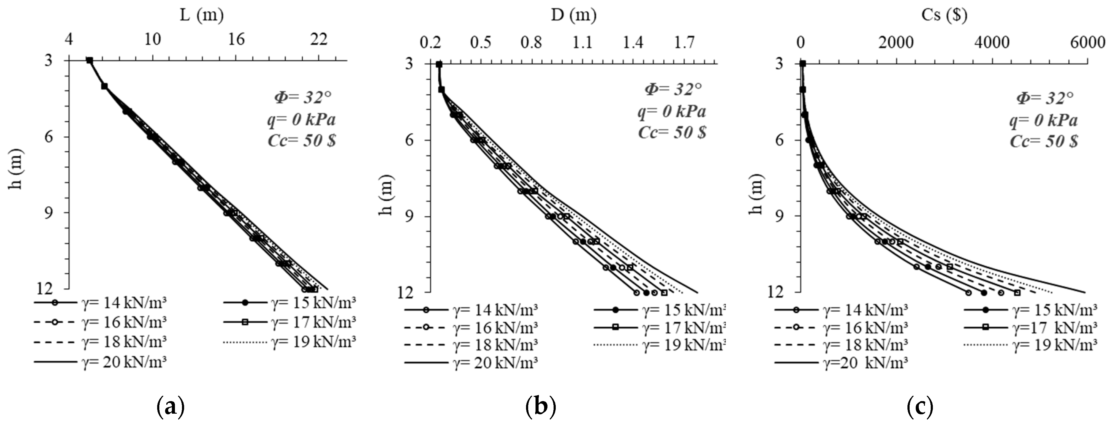
Figure 8 to realize the alteration effect of soil unit weight via the increase of depth. The increase tendency of the pile length and diameter can be classified as the same as those shown in
Figure 5. After 4 m excavation depth, the change of pile diameter dominantly governs the relationship between stability and dimensions. This situation can be the proof that the change of diameter has a significant effect on the stability of piled systems. However, different from
Figure 5, it is a noticeable point that the optimization algorithm can find an appropriate cross-section for deep excavations, although the soil unit weight increases.
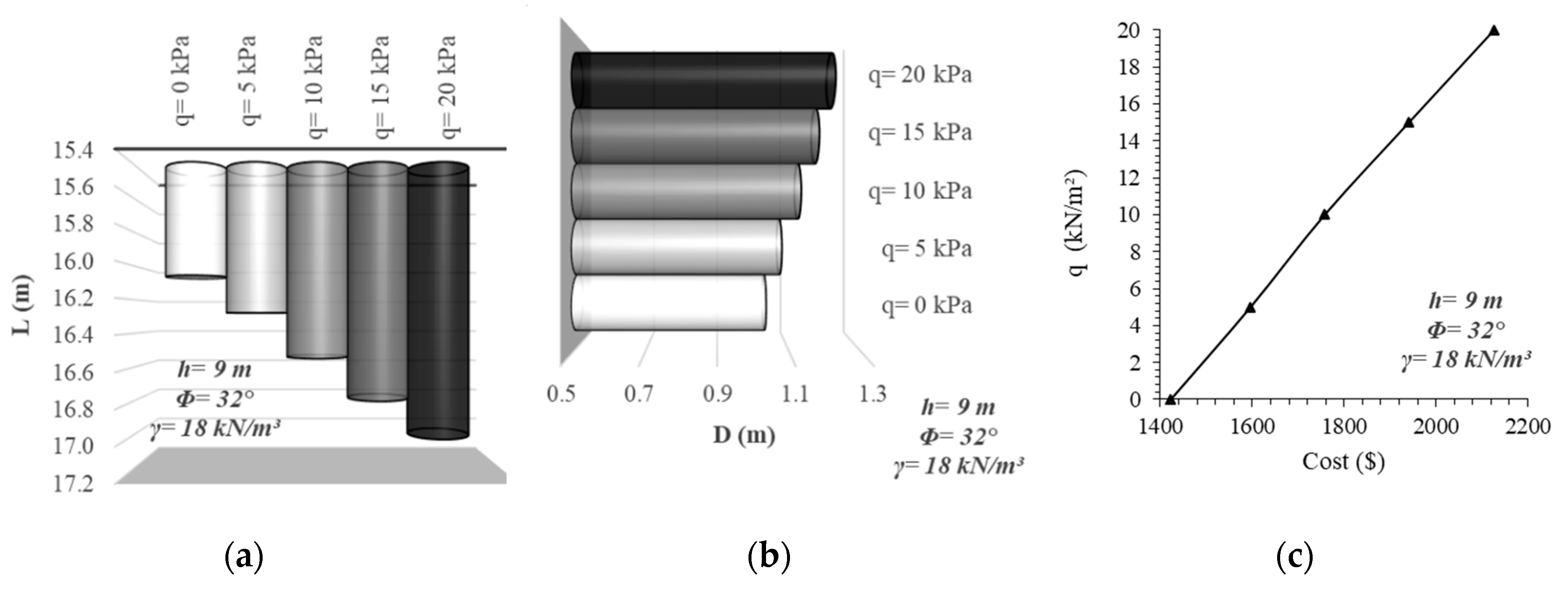
For the evaluation of the influence of surcharge load on the behavior of cantilever soldier piles, only the load magnitudes are selected as variables, and the other mentioned variable parameters are fixed as specific values. Three reference excavation depths are selected (
h = 9-6-3 m), and a specific soil profile with 18 kN/m
3 unit weight and 32° shear strength angle is used for the comparison of the effects of surcharge load application adjacent to the top of the retaining pile system. The change of surcharge load that is applied on the active side of the structural system is taken into account by selecting the load values 0, 5, 10, 15, and 20 kPa. In
Figure 9, the reference excavation depth is selected as 9 m, and dimensions of the systems are selected according to this situation. The increase of the external loading lengthens and enlarges the pile and raises the unit costs as expected. The length of the pile is increased approximately 5%, and the diameter of the pile is increased 20% by the differentiation of surcharge loading between the upper and lower bounds. Besides this, the increase of surcharge load to 20 kPa raises the material costs 50%, and this ultimate rising happens directly proportional with the increase steps of load. The cost has raised to
$2126 from
$1422 with the increase of surcharge load to 20 kPa.
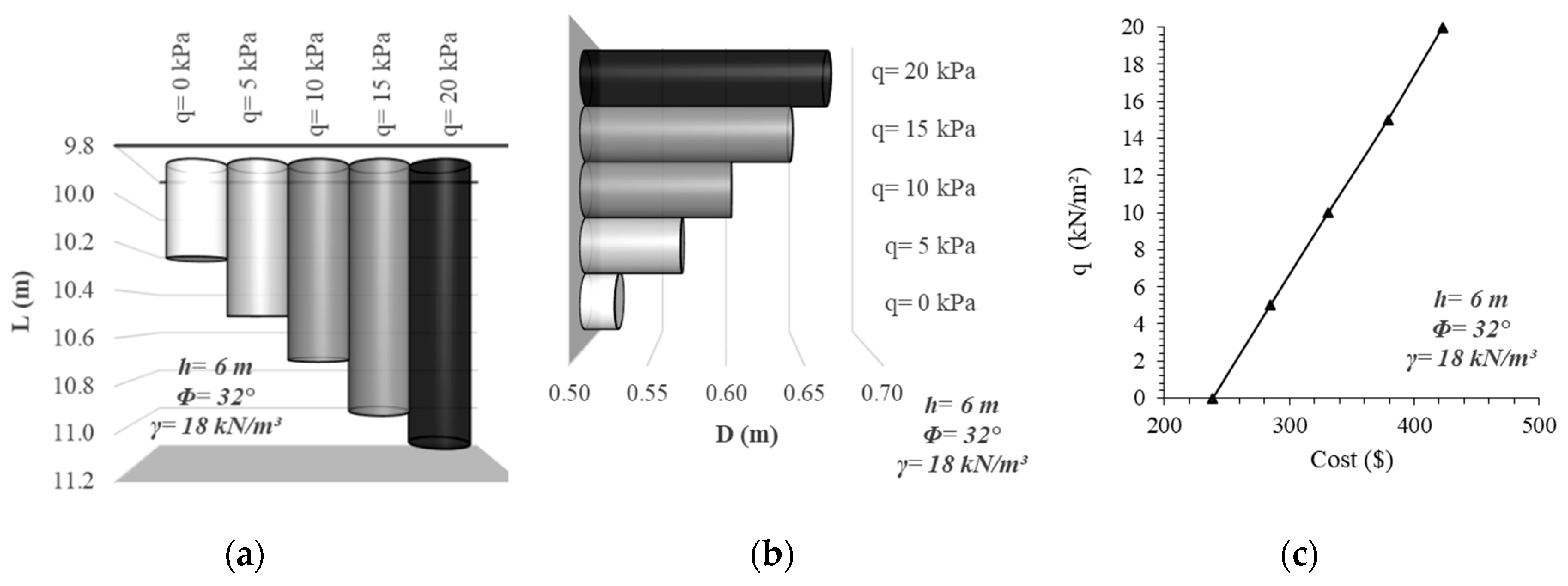
Figure 10 is drawn for 6 m excavation depth to examine the surcharge loading effect for relatively shallow depth.
In this case, the length of the pile is raised 8%, the pile diameter is increased 28%, and the unit cost is increased 77% due to the increase of external load to 20 kPa. The cost has raised to
$423 from
$239 with the increase of surcharge load to 20 kPa. This situation exhibits that surcharge load application is a significant parameter in the design of cantilever soldier piles, especially for shallow depths. The analyses are repeated by changing the excavation depth of 3 m, but there are no differences of the design dimensions of the pile. If only the soil is loose and the unit weight of the soil is high, an approximately 1% change of pile length happens for 3 m excavation depth.
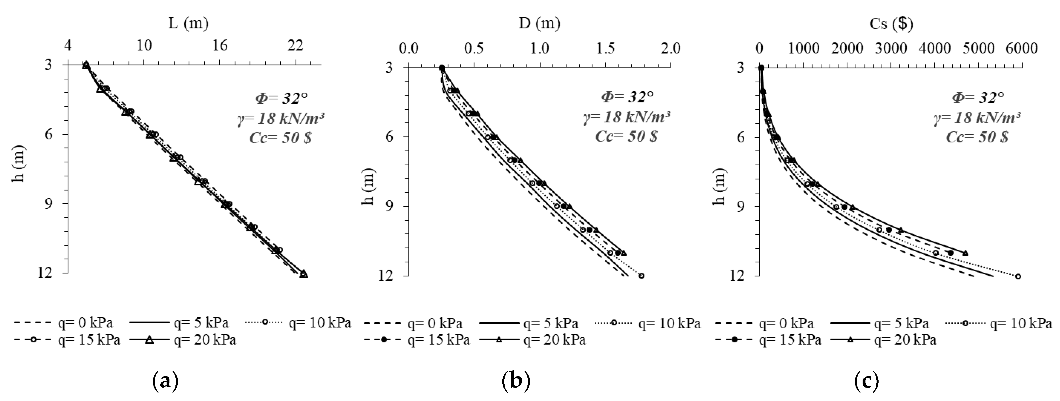
Figure 11 is drawn to show the change of design and cost of the cantilever soldier pile via the excavation depth for different loading situations. The shear strength angle of the soil is selected to be 32°, and the unit weight is assumed to be 18 kN/m
3 for the reference case. It is clearly seen from the comparison of
Figure 11a,b that the pile diameter is the parameter that has the most influence on the design. The increase rate of the external load does not have any significant effect on the length of the pile. Besides, for the excavation depths that are deeper than 11 m, according to the increase of external load, the optimization algorithm cannot obtain a proper design ensuring both geotechnical safety and structural adequacy.
In
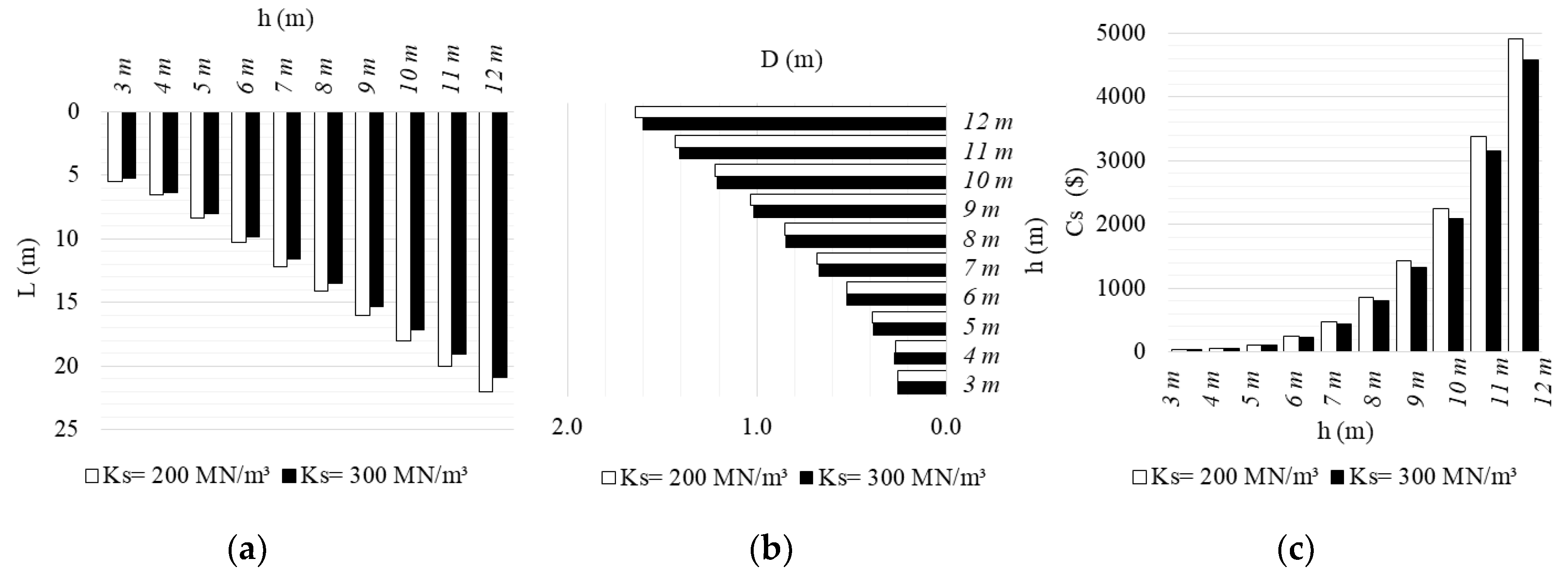
Figure 12, the effect of the coefficient of soil reaction change is investigated. All analyses up to this part of the study were repeated for
KS = 300 MN/m
3. The coefficient of reaction can be identified as the preliminary effective parameter for the determination of the embedment depth of the soldier pile according to Equations (5) and (6). This parameter is inversely proportional to the length of embedment, so it is expected that the increase of coefficient of soil reaction from 200 MN/m
3 to 300 MN/m
3 shortens the pile length and/or straightens the diameter of the pile. This prediction is proven in
Figure 12 that the increase of the coefficient of soil reaction leads to decreasing the design dimensions and related cost. The
Ks values used to perform optimization analyses of this study are selected from a well-known tabulated suggestion [
14] to define dense sands. However, it has to be noted that the proposed value of coefficient of soil reaction is changed between 64,000 and 200,000 kN/m
3 for medium to dense sandy soils [
42]. In addition to all these, the change of concrete cost is evaluated, reanalyzing all the fictionalized cases again.
The second part of the study involves controlling the design dimensions, which are obtained from the solutions of the harmony search algorithm with well-known two-dimensional finite element software. A total of 72 different case analyses are done to control the acceptableness of the optimization algorithms to the geotechnical cantilever soldier pile wall design problem.
However, only the results of three different excavation depths and two different loading conditions are shown for the discussion of two methods. Some of the design parameters are selected as constant values. The shear strength angle of the surrounding soil mass is assumed to be 32°, and the unit weight of the soil is 18 kN/m
3 for all the analyses conducted. The pile dimensions acquired from the HS algorithm analyses are given in
Table 4 for
q = 0 kPa and in
Table 5 for the
q = 10 kPa loading condition.
A finite element model is created according to the calculated dimensions, and the model boundaries are considered too large not to affect the distribution of stresses. The maximum moment values, shear stresses, and pivot point locations are compared, and also the safety of the envisaged system is procured.
Table 6,
Table 7, and
Table 8 represent the results of the analyses conducted with both methods studied in this study.
The results of the HS algorithm solutions are represented with the “OR” abbreviation, and the results of the finite element solutions are represented with the “PR” abbreviation in the tables.
In
Table 6,
Table 7 and
Table 8, the compatibility of OR and PR results ensures a satisfaction. The application of static limit equilibrium equations for the application of beams on elastic soil theory supplies the safety degree to be at the boundary situation (Factor of Safety:
FoS: 1.0).
The factor of safety values obtained from finite element analyses shows that the envisaged design dimensions are partially safe (FoS > 1.0). However, the admissibility criteria of this safety degree can change in terms of the project type and requirements.
A comparison of the values given in
Table 6 and
Table 8 shows that the increase of the excavation depth causes an increase in the relative result difference between the suggested methods. This relative difference is greatly increased for the excavation depths bigger than 8 m, and stability conditions cannot be ensured after 9 m excavation depth in the analysis conducted with the software. It is a remarkable detail that the optimization analysis cannot also solve the stability problem for 10 m excavation depth when the shear strength angle is low. The integrated evaluation of both methods shows that the applicability of cantilever soldier piles is limited to a critical excavation depth. In this context, it can be said that the application of the HS algorithm gives more optimistic results.


