Featured Application
A series of hypervelocity impact experiments were conducted to study the crater characteristics of granite. The effects of the impact velocity and the projectile–target density ratio on the crater parameters were analyzed. Regression prediction equations for the crater parameters were proposed. The research results are great of significance for damage analysis and protection of rocks under meteorite impact or kinetic energy weapon attack.
Abstract
To understand and analyze crater damage of rocks under hypervelocity impact, the hypervelocity impact cratering of 15 shots of hemispherical-nosed cylindrical projectiles into granite targets was studied within the impact velocity range of 1.91–3.99 km/s. The mass of each projectile was 40 g, and the length–diameter ratio was 2. Three types of metal material were adopted for the projectiles, including titanium alloy with a density of 4.44 g/cm3, steel alloy with a density of 7.81 g/cm3, and tungsten alloy with a density of 17.78 g/cm3. The projectile–target density ratio (ρp/ρt) ranged from 1.71 to 6.86. The depth–diameter ratios (H/D) of the craters yielded from the experiments were between 0.14 and 0.24. The effects of ρp/ρt and the impact velocity on the morphologies of the crater were evaluated. According to the experimental results, H/D of craters is negatively correlated with the impact velocity, whereas the correlation between H/D and ρp/ρt is weak positive. The crater parameters were expressed as power law relations of impact parameters by using scaling law analysis. The multiple regression analysis was utilized to obtain the coefficients and the exponents of the relation equations. The predicted values of the regression equations were close to the experimental results.
1. Introduction
Hypervelocity impact craters are ubiquitous in many areas, including asteroid collisions, meteorite impact on Earth-like planets, artificial space debris, or micrometeoroid impact on spacecraft. Consequently, the crater phenomenon has been of great concern and continuously studied by researchers from the fields of astrophysics, geophysics, and aerospace engineering [1,2]. The experimental method is a vital means of studying the hypervelocity impact crater phenomena [3,4]. The most common launching technique in impact experiments is the two-stage light-gas gun [5,6,7]. A large number of hypervelocity impact experiments have been widely used to study hypervelocity impact crater characteristics over the past six decades. Diverse influencing factors on the crater morphology have been studied, such as the impact velocity [8,9,10,11], the impact angle [12,13,14,15,16], the material characteristic of the collision object [17,18,19,20,21,22,23], and the projectile shape [24,25,26,27]. Based on dimensional analysis, several equations were proposed to represent the relationship between the crater parameters and the impact condition parameters [28,29,30,31].
The material properties of the targets made of geological materials are more complex than those of metals, leading to a complicated effect on hypervelocity impact craters. It has been found that the properties of geological materials, such as the pores, porosity saturation, and moisture content, can influence crater morphology [32]. In addition, the influence of ρp/ρt on hypervelocity impact craters cannot be neglected. Smreker et al. [33] conducted hypervelocity impact experiments using aluminum and steel spherical projectiles and diorite targets. The study showed that increasing ρp/ρt leads to higher H/D of the impact crater. Poelchau et al. [34] conducted hypervelocity impact experiments using aluminum, steel, and iron meteorite spherical projectiles and sandstone targets, and the relationship between ρp/ρt and H/D was also found to be significantly positively correlated. However, Burchell and Johnson [35] conducted a series of hypervelocity impact experiments on small icy bodies by using spherical projectiles of various density, in which a vague correlation between H/D and ρp/ρt was observed. Therefore, to understand the detailed effect of ρp/ρt on the crater characteristics, experimental studies on hypervelocity impact cratering remain necessary. Hypervelocity impact experiments of non-spherical projectiles on the geological material targets are still scarce in the literature. There are few data available for non-spherical projectile hypervelocity impact experiments using rocks.
The main purpose of this study was to investigate the hypervelocity impact craters of granite targets under non-spherical projectiles and the influence of ρp/ρt on the crater morphology. By using hemispherical-nosed cylindrical projectiles, 15 shots of hypervelocity impact cratering into granite targets were conducted at the impact velocities distributed from 1.91 to 3.99 km/s. These projectiles were made of different metals including titanium alloy, alloy steel, and tungsten alloy. The mass of each projectile was about 40 g, and the length-diameter ratio was 2. The effects of ρp/ρt and the impact velocity on the crater characteristics of the targets were evaluated. Then, the crater parameters were expressed as power law relations of the impact parameters through the scaling law analysis. The research results can provide some insight for damage analysis and protection of rocks under meteorite impact or kinetic energy weapon attack.
2. Experimental Methods
Fifteen shots of hemispherical-nosed cylindrical projectiles hypervelocity impact on granite targets were carried out. The two-stage light-gas gun was employed to launch the projectiles with impact velocities varied from 1.91 to 3.99 km/s. The projectiles were made of different metals, including titanium alloy, alloy steel and tungsten alloy. The experimental data including depth, diameter, and volume of the craters were measured and recorded meticulously.
2.1. Projectiles
The hemispherical-nosed cylindrical projectiles with mass of 40 g and the length–diameter ratio of 2 were adopted in the present hypervelocity impact experiments. Three metal types of different densities were selected to make the projectiles, which were TC4 titanium alloy, 30CrMnSiA alloy steel, and 93 W tungsten alloy. Figure 1 shows the dimensions and the photographs of the projectiles. For the TC4 projectiles, the density was 4.44 g/cm3, the length was 3.668 cm, the diameter was 1.834 cm, and the nose radius was 0.917 cm. For the 30CrMnSiA projectiles, the density was 7.81 g/cm3, the length was 3.048 cm, the diameter was 1.524 cm, and the nose radius was 0.762 cm. For the 93 W projectiles, the density was 17.78 g/cm3, the length was 2.328 cm, the diameter was 1.164 cm, and the nose radius was 0.582 cm.
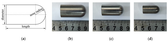
Figure 1.
Dimensions and photographs of projectiles: (a) schematic of dimensions of projectile; (b) photograph of TC4 projectile; (c) photograph of 30CrMnSiA projectile; (d) photograph of 93 W projectile.
2.2. Targets
The cylindrical granite targets made of a combination of granite target core, steel casing, and concrete filler were used in the test. Figure 2 displays the dimensions and the photos of a typical granite target. The target core with the diameter of 100 cm was assembled from five layers of granite discs. Three of the five granite discs were 10 cm in thickness and two were 25 cm in thickness, and the five granite discs were mirror-polished and successively conglutinated together by epoxy. The adhesive strength of the epoxy used was about 18 MPa and much higher than the tensile strength 4.2 MPa of the granite measured by the Brazilian disc experiment. That provided enough strength to prevent spallation from the conglutinations between plates. The total length of the target cores is 80 cm. A set of thin-film pressure sensors was installed at the center of the interfaces between the granite discs to record the initial stress waves caused by the impact. The granite target core was encased by a steel casing, which was 5 mm in thickness, 120 cm in diameter, and 80 cm in length. To fix and confine the granite target core, concrete with cubic compressive strength of 60 MPa was cast in the gap between the granite target core and the steel casing. Based on experimental results obtained by Poelchau et al. [34], the diameter of the granite targets used in this study was 50 times more than the maximum diameter of the projectiles, such that the impact crater would not exceed the target in diameter. The steel casing provided a circumferential restraint for the granite target to prevent the target disintegration from the radial crack of the impact crater extending to the circumference of the granite target.
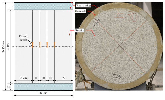
Figure 2.
Dimensions and photographs of a target sample.
The target granite was light grayish white with dark spots, which was quarried from the Tongbai Mountains in Central China. X-ray diffraction (XRD) analysis was performed, and the result shows that the granite mainly consisted of 54.4% quartz, 14.3% anorthoclase, 13.4% albite, 12.7% biotite, and 5% orthoclase. The density (ρt = 2.59 g/cm3) was obtained by dividing the weight of the sample by the volume. The porosity was 0.77%. Uniaxial compressive strength Y was 131.24 MPa, which was measured based on unconfined cylindrical granite samples (50 × 100 mm) in a uniaxial test machine at a displacement rate of 0.02 mm/s.
2.3. Set-Up
Figure 3 presents the two-stage light-gas gun employed to launch the projectiles. The pump tube was 100 mm in diameter and was filled with high-pressure hydrogen gas. The launch tube was 30 mm in diameter and was connected to a target chamber of 2000 mm in diameter. In the target chamber, the target was positioned with its impact surface perpendicular to the axis of the launch tube and its axis coaxial with the launch tube. The chamber pressure was pumped to about 5000 Pa. Measurement of the impact velocity was conducted by using a set of laser barriers positioned in the impact trajectory.
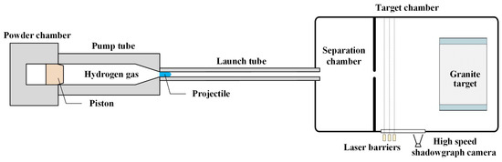
Figure 3.
Schematic of a two-stage light-gas and experimental set-up.
A laser high-speed shadowgraph camera system, with the ability to film at up to 50,000 frames per second, was adopted to capture the ballistic trajectory of the projectiles. Figure 4 presents a typical record of the ballistic trajectory of a projectile before impact, indicating that the projectile and the target collided nearly perpendicularly. In some shots, however, a small yaw angle was observed from the laser shadowgraph images.
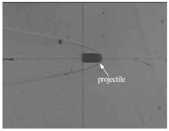
Figure 4.
The typical record of the ballistic trajectory of a projectile before impact.
The experimental parameters of concern in this study are provided in Table 1, including the projectile density ρp, the projectile mass mp, the projectile length l, the projectile diameter d, the projectile length–diameter ratio l/d, the impact velocity u, the impact kinetic energy Ek, and the yaw angle. The mass and the length–diameter ratio were kept basically constant for all projectiles. The measured impact velocities were fixed roughly at 2.0, 2.5, 3.0, 3.5, and 4.0 km/s in the shots.

Table 1.
Experimental parameters.
3. Experimental Results
Figure 5 shows morphological characteristics of a typical experimental impact crater in granite, in which a central depression, crater rim, stuck spall piece, circumferential fracture, and radial cracks are identified. Figure 6 lists experimental impact craters of all the granite targets except shot no. 9. As shown in Figure 6, the local damage created by impact cratering was within the surfaces of the granite targets. All the craters showed approximately circular depressions within highly crushed target material in the center of the crater. The rims of the craters were irregular and non-circular in shape, which was caused by fragment spalling from the target. Several visible radial cracks with different lengths were located along the crater rim. On the surfaces of some targets, visible circumferential fractures could be observed outside the craters (shot No. 12 in Figure 6l), and the initial spall pieces were still stuck within the crater (shot No. 3 in Figure 6c).
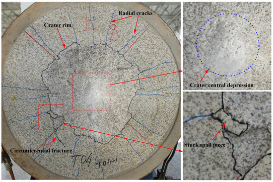
Figure 5.
Morphological characteristics of a typical experimental impact crater in granite (Shot No. 9).
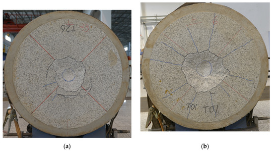
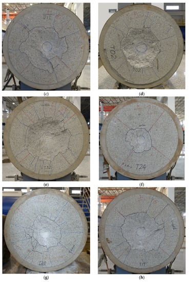
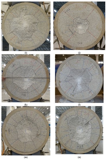
Figure 6.
Experimental impact craters of the granite targets: (a) Shot No. 1; (b) Shot No. 2; (c) Shot No. 3; (d) Shot No. 4; (e) Shot No. 5; (f) Shot No. 6; (g) Shot No. 7; (h) Shot No. 8; (i) Shot No. 10; (j) Shot No. 11; (k) Shot No. 12; (l) Shot No. 13; (m) Shot No. 14; (n) Shot No. 15.
A three-dimensional (3D) laser scanner with a spatial resolution of 0.1 mm was employed to capture the morphologies and the dimensions of the craters. The high-precision 3D digital elevation models (3D-DEMs) of all the impact craters were restructured based on the scanning data, which contain the 3D spatial coordinate data of the impact craters. Figure 7 shows the three different views of a typical 3D-DEM of the impact crater morphology of shot No. 10, in which the crater depth from the original impact surface is identified by a color card. In Figure 7c, the approximately circular depression is identified with a yellow dashed line. The 3D-DEMs of the impact craters were handled to obtain precise crater parameters. Eighteen individual sections through the deepest point of an impact crater were produced, and the sections were spaced 10° from each other as shown in Figure 7a. Figure 8 illustrates the typical diagrammatic transect of the crater, in which the dimensions of the crater are identified. The crater diameter is the average of diameters of all 18 sections of the crater.
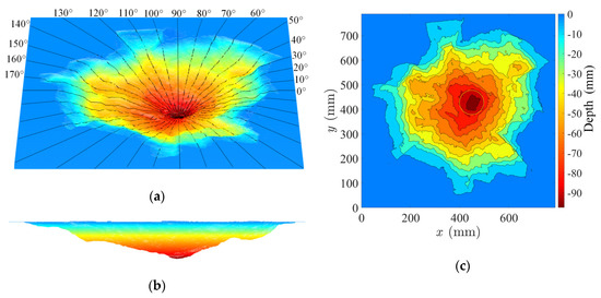
Figure 7.
Three-dimensional (3D) digital elevation model of impact crater (Shot No. 10): (a) oblique view; (b) lateral view; (c) top view with depth contour lines.
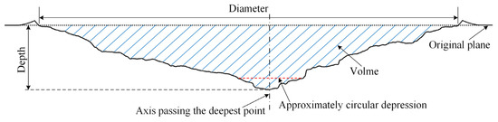
Figure 8.
Schematic of the section of the impact crater (Shot No. 10).
The crater parameters of all the impact craters obtained in the experiments are listed in Table 2, including the depth H, the diameter D, the volume V, the depth-diameter ratio H/D, the dimensionless depth H/l, the dimensionless diameter D/d, and dimensionless volume V/ld2 of the craters.
Table 2.
Experimental impact crater parameters.
After the impact, the projectiles were deformed, eroded and broke into small pieces, all of which fell to the ground. No projectile was observed to have stuck in the impact crater. The remainders of some projectiles were recovered carefully after the impact experiments. Figure 9 shows the photographs of the typical recovered projectiles. The effects of deformation and damage of the projectiles on impact craters will be a topic of more detailed study in the future.
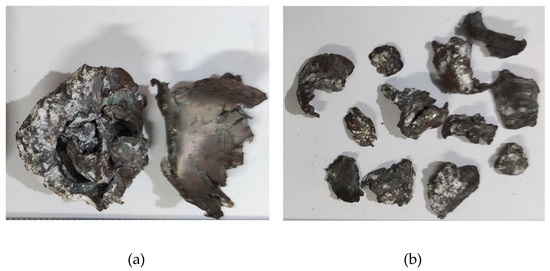
Figure 9.
The photographs of the typical recovered projectiles: (a) Shot No. 7; (b) Shot No. 10.
4. Discussion
4.1. Influences of Impact Velocity
Figure 10 presents the influences of the impact velocity on the dimensionless crater depth, diameter, volume, and the crater H/D ratio. Figure 10a–c, indicate that the dimensionless crater depth, diameter, and volume grow with the increase of the impact velocity for all the three different projectile densities. However, the higher projectile density leads to the faster growth rates of these three crater parameters, indicating that the projectile density plays an essential role in the impact crater by affecting the dimensions of the crater. As shown in Figure 10d, the ratio H/D decreases with the increase of the impact velocity. This phenomenon indicates that H/D negatively correlates with the impact velocity, which is identical to that reported by Poelchau et al. [34].
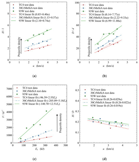
Figure 10.
The influences of the impact velocity on crater depth, diameter, volume, and crater H/D ratio: (a) dimensionless crater depth versus impact velocity; (b) dimensionless crater diameter versus impact velocity; (c) dimensionless crater volume versus impact kinetic energy; (d) crater H/D ratio versus impact velocity.
Spallation created by the interaction of the shock wave and the rarefaction wave near the target surface makes a contribution to excavation and final crater shape [36,37,38], and will likewise have an influence on crater diameters and, thereby, on the crater H/D ratios and crater volumes. The spallation effect is expected to be dominated by the impact velocity, and the material characteristic of the collision objects [36,37]. This will be a topic for more detailed study in the future.
4.2. Influences of Projectile–Target Ratio
Figure 11 presents the influences of the projectile–target ratio on the dimensionless crater depth, diameter, volume, and the crater H/D ratio. The dimensionless crater depth, diameter, and volume increase with the increase of ρp/ρt, as shown in Figure 11a–c. These three dimensionless crater parameters positively correlate with ρp/ρt.
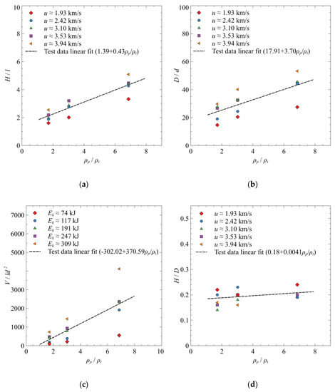
Figure 11.
The influences of ρp/ρt on crater depth, diameter, volume, and crater H/D ratio: (a) dimensionless crater depth versus ρp/ρt; (b) dimensionless crater diameter versus ρp/ρt; (c) dimensionless crater volume versus ρp/ρt; (d) crater H/D ratio versus ρp/ρt.
The crater H/D ratio increases slightly (the slope is only 0.0041) with the increase of ρp/ρt, as shown in Figure 11d. This implies that the positive correlation between the H/D ratio and the ρp/ρt ratio is relatively weak. However, the experimental results of Smreker [33] and Poelchau [34] show that the positive correlation between the H/D ratio and the ρp/ρt ratio is stronger. The difference of the correlations may be caused by the reason that the range of ρp/ρt (1.71–6.86) in this study is wider than those in the experiments by Smreker [33] (ρp/ρt = 1.05–2.9) and Poelchau [34] (ρp/ρt = 1.37–4.23).
4.3. Scaling Laws of Impact Crater Parameters
The scale analysis is an effective way to analyze the influence of the impact parameters on the impact crater dimensions. In accordance with the point source solutions proposed by Holsapple [28,30], the crater parameters can be represented as functions of the impact parameters. The impact parameters embody the projectile diameter d, the projectile density ρp, the impact velocity u, the target density ρt, and the target compressive strength Y. In addition, the projectile length l is added to represent the shape influence of the projectile. Then, the crater depth H can be expressed as below:
where the general symbol F represents an arbitrary function, and the symbol Πm denotes the set of dimensionless material parameters.
The “coupling parameter” C, in which the projectile length l is added to represent the effect of the projectile shape, is given as below:
Then, Equation (1) can be rewritten by adopting the coupling parameters as follows:
The coupling parameter with length scale is expressed as below:
where the term l/d is the length–diameter ratio of the projectile.
Then Equation (3) can be scaled using Equation (4) as follows:
where k is defined as a function of Πm.
Then, Equation (5) can be rewritten in a dimensionless form as follows:
By using the dimensionless parameter H/l instead of H/d, Equation (6) can be rewritten as follows:
In this study, the length–diameter ratios l/d of all the projectiles keep a constant of 2. Then, (l/dss)ξ−1 is also a constant coefficient. Set K = k(l/d)ξ−1, then Equation (7) can be simplified as follows:
The multiple regression analysis was adopted for the experimental data to calculate the coefficient K and the exponents μ and ν. Therefore, the logarithmic form of Equation (8) can be obtained as follows:
Following the above process, similar logarithm equations for the dimensionless diameter and volume can be obtained as below:
By using the multiple regression analysis on Equations (9)–(11), the predicted regression equations for the impact crater parameters are achieved as follows:
The coefficients of determination (R-squared) of Equations (12)–(14) are 0.975, 0.955, and 0.978, respectively, and the standard estimation errors are 2.6%, 3.6%, and 7.3%, respectively. All the coefficients of determination are higher than 0.95, while all the standard estimation errors are lower than 7.5%, indicating that the regression equations have good reliability with small error for the estimation of the crater parameters. Figure 12 illustrates the comparison between the predicted values of the regression equations and the experimental results. The dashed lines with slope of 1 through the coordinate origin represent the predicted values of the regression equations for the dimensionless crater parameters. Each experimental result corresponding to the predicted one is distributed along the dashed line of estimation, which verifies the accuracy of the regression equations on predicting the crater parameters.
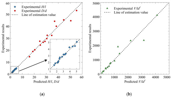
Figure 12.
The experimental results versus the predicted values of the impact crater parameters: (a) experimental H/l and D/d versus predicted values; (b) experimental V/ld2 versus predicted values.
The exponents of Equations (12) and (13) are compared to study the dependence relationships of the crater parameters on the impact parameters. The crater depth has almost the same dependence on the impact velocity and the ρp/ρt ratio. The crater diameter is more dependent on the impact velocity than the ρp/ρt ratio. Compared to the crater diameter, the crater depth is less affected by the impact velocity and more affected by the ρp/ρt ratio. As presented in Equation (14), the crater volume is dominated by the impact kinetic energy.
5. Conclusions
In this study, the influences of the impact velocity and the projectile–target density ratio on the impact crater were studied by experimental and dimensional analysis. It should be noted that the impact velocity effect on the crater includes the partial contribution of the interaction of the shock wave and the rarefaction wave near the target surface to excavation and final crater shape. The results of this investigation are as follows:
- (1)
- Fifteen shots of hypervelocity impact cratering into granite targets were carried out using hemispherical-nosed cylindrical projectiles with the impact velocity range of 1.91–3.99 km/s. The mass of each projectile was 40 g, and the length–diameter ratio was 2. Projectile materials were TC4 titanium alloy, 30CrMnSiA alloy steel, and 93W tungsten alloy. The projectile–target density ratio ranged from 1.71 to 6.86.
- (2)
- The crater H/D ratio varied between 0.14 and 0.24, which shows negative correlation with the impact velocity and weak positive correlation with the projectile–target density ratio.
- (3)
- Based on the dimensional analysis, the crater parameters were expressed as power law equations of impact parameters, whose coefficients and exponents were calculated by regression analysis, and the values predicted by the regression equations agreed well with the experimental results with good reliability.
- (4)
- The crater depth is more dependent on the projectile–target density ratio than the crater diameter.
Author Contributions
X.W. proposed the study idea of this paper, designed the experiment, and analyzed the influence of the projectile–target density ratio on the craters. J.L. analyzed the influence of the impact velocity. B.W., D.K., and J.H. conducted the experiment. X.X. measured experimental parameters. X.B. conducted the dimensional analysis and prepared the manuscript. All authors have read and agreed to the published version of the manuscript.
Funding
This research received no external funding.
Acknowledgments
Jingui Qin and Mafa Wang of China Aerodynamics Research and Development Center are greatly appreciated for their help and technical support during conducting hypervelocity impact experiments.
Conflicts of Interest
The authors declare no conflict of interest.
Nomenclature
| ρp | Projectile density |
| mp | Projectile mass |
| l | Projectile length |
| d | Projectile diameter |
| l/d | Projectile length–diameter ratio |
| u | Impact velocity |
| Ek | Impact kinetic energy |
| ρt | Target density |
| Y | Uniaxial compressive strength of the target granite |
| ρp/ρt | Projectile–target density ratio |
| H | Crater depth |
| D | Crater diameter |
| V | Crater volume |
| H/D | Crater depth-diameter ratio |
| H/l | Dimensionless crater depth |
| D/d | Dimensionless crater diameter |
| V/ld | Dimensionless crater volume |
References
- Kenkmann, T.; Poelchau, M.H.; Wulf, G. Structural geology of impact craters. J. Struct. Geol. 2014, 62, 156–182. [Google Scholar] [CrossRef]
- Katz, S.; Grossman, E.; Gouzman, I.; Lempert, G.; Brill, A.; Wagner, H.D. Effect of Hypervelocity Impactor Properties on Target Materials Damage. J. Spacecr. Rockets 2012, 49, 232–273. [Google Scholar] [CrossRef]
- Kinslow, R.; Cable, A.J. High-Velocity Impact Phenomena; Academic Press: New York, NY, USA, 1970; ISBN 978-0-12-408950-1. [Google Scholar]
- Heberling, T.; Terrones, G.; Weseloh, W. Hydrocode simulations of a hypervelocity impact experiment over a range of velocities. Int. J. Impact Eng. 2018, 122, 1–9. [Google Scholar] [CrossRef]
- Chhabildas, L.C.; Davison, L.; Horie, Y. (Eds.) High-Pressure Shock Compression of Solids VIII: The Science and Technology of High-Velocity Impact; Springer: Heidelberg, Berlin, Germany, 2005; ISBN 978-3-540-27168-0. [Google Scholar]
- Lexow, B.; Wickert, M.; Thoma, K.; Schaefer, F.; Poelchau, M.H.; Kenkmann, T. The extra-large light-gas gun of the Fraunhofer EMI: Applications for impact cratering research. Meteorit. Planet. Sci. 2013, 48, 3–7. [Google Scholar] [CrossRef]
- Putzar, R.; Schaefer, F. Concept for a new light-gas gun type hypervelocity accelerator. Int. J. Impact Eng. 2016, 88, 118–124. [Google Scholar] [CrossRef]
- Charters, A.C.; Locke, G.S., Jr. A Preliminary Investigation of High-speed Impact: The Penetration of Small Spheres into Thick Copper Targets; NACA: Moffett Field, CA, USA, 1958. [Google Scholar]
- Murr, L.E.; Quinones, S.A.; Ferreyra, E.; Ayala, A.; Valerio, O.L.; Horz, F.; Bernhard, R.P. The low-velocity-to-hypervelocity penetration transition for impact craters in metal targets. Mater. Sci. Eng. Struct. Mater. Prop. Microstruct. Process. 1998, 256, 166–182. [Google Scholar] [CrossRef]
- Orphal, D.L.; Franzen, R.R. Penetration of confined silicon carbide targets by tungsten long rods at impact velocities from 1.5 to 4.6 km/s. Int. J. Impact Eng. 1997, 19, 1–13. [Google Scholar] [CrossRef]
- Barnouin-Jha, O.S.; Yamamoto, S.; Toriumi, T.; Sugita, S.; Matsui, T. Non-intrusive measurements of crater growth. Icarus 2007, 188, 506–521. [Google Scholar] [CrossRef]
- Crawford, G.; Hill, D.; Rose, F.E.; Zee, R.; Best, S.; Crumpler, M. Hypervelocity Impact Study: The Effect of Impact Angle on Crater Morphology; NASA: Washington, DC, USA, 1993.
- Burchell, M.J.; Mackay, N.G. Crater ellipticity in hypervelocity impacts on metals. J. Geophys. Res. 1998, 103, 22761–22774. [Google Scholar] [CrossRef]
- Burchell, M.J.; Grey, I.D.S. Oblique hypervelocity impacts on thick glass targets. Mater. Sci. Eng. Struct. Mater. Prop. Microstruct. Process. 2001, 303, 134–141. [Google Scholar] [CrossRef]
- Burchell, M.J.; Whitehorn, L. Oblique incidence hypervelocity impacts on rock. Mon. Not. R. Astron. Soc. 2003, 341, 192–198. [Google Scholar] [CrossRef]
- Michikami, T.; Hagermann, A.; Morota, T.; Haruyama, J.; Hasegawa, S. Oblique impact cratering experiments in brittle targets: Implications for elliptical craters on the Moon. Planet. Space Sci. 2017, 135, 27–36. [Google Scholar] [CrossRef]
- Kinard, W.H.; Collins, R.D. An Investigation of High-Velocity Impact Cratering into Nonmetallic Targets and Correlation of Penetration Data for Metallic and Nonmetallic Targets; NASA: Washington, DC, USA, 1961.
- Cannon, E.T.; Turner, G.H. Cratering in Low-Density Targets; NASA: Washington, DC, USA, 1967.
- Clough, N.; McMillan, A.R.; Lieblein, S. Crater Characteristics of 11 Metal Alloys under Hyper-Velocity Impact Including Effects of Projectile Density and Target Temperature; NASA: Washington, DC, USA, 1969.
- Hörz, F.; Cintala, M.J.; Bernhard, R.P.; See, T.H. Cratering and penetration experiments in teflon targets at velocities from 1 to 7 km/s. Int. J. Impact Eng. 1995, 17, 419–430. [Google Scholar] [CrossRef][Green Version]
- Silvestrov, V.V.; Plastinin, A.V.; Pai, V.V.; Yakovlev, I.V. Hypervelocity impact on isotropic composites with metal or ceramic inclusions. Int. J. Impact Eng. 1997, 20, 733–742. [Google Scholar] [CrossRef]
- Nechitailo, N. Hypervelocity Penetration into Soil. Procedia Eng. 2015, 103, 427–435. [Google Scholar] [CrossRef][Green Version]
- Prieur, N.C.; Rolf, T.; Luther, R.; Wuennemann, K.; Xiao, Z.; Werner, S.C. The effect of target properties on transient crater scaling for simple craters. J. Geophys. Res.-Planets 2017, 122, 1704–1726. [Google Scholar] [CrossRef]
- Denardo, B.P.; Nysmith, C.R.; Summers, J.L. Projectile Shape Effects on Hypervelocity Impact Craters in Aluminum; NASA: Washington, DC, USA, 1969.
- Hohler, V.; Stilp, A.J. Hypervelocity impact of rod projectiles with L/D from 1 to 32. Int. J. Impact Eng. 1987, 5, 323–331. [Google Scholar] [CrossRef]
- Kadono, T.; Suzuki, A.I.; Araki, S.; Asada, T.; Suetsugu, R.; Hasegawa, S. Investigation of impact craters on flat surface of cylindrical targets based on experiments and numerical simulations. Planet. Space Sci. 2018, 163, 77–82. [Google Scholar] [CrossRef]
- Itagaki, Y.; Tamura, H.; Watanabe, Y.; Taniyama, K.; Takashima, A. Effects of head shape of projectiles on hypervelocity impact cratering on aluminum 5052 alloy targets at 7 km/s. Int. J. Impact Eng. 2019, 123, 38–47. [Google Scholar] [CrossRef]
- Holsapple, K.A.; Schmidt, R.M. Point source solutions and coupling parameters in cratering mechanics. J. Geophys. Res. 1987, 92, 6350–6376. [Google Scholar] [CrossRef]
- Westine, P.S.; Mullin, S.A. Scale modeling of hypervelocity impact. Int. J. Impact Eng. 1987, 5, 693–701. [Google Scholar] [CrossRef]
- Holsapple, K.A. The Scaling of Impact Processes in Planetary Sciences. Annu. Rev. Earth Planet. Sci. 1993, 21, 333–373. [Google Scholar] [CrossRef]
- Watts, A.J.; Atkinson, D. Dimensional scaling for impact cratering and perforation. Int. J. Impact Eng. 1995, 17, 925–935. [Google Scholar] [CrossRef]
- Kenkmann, T.; Wuennemann, K.; Deutsch, A.; Poelchau, M.H.; Schaefer, F.; Thoma, K. Impact cratering in sandstone: The MEMIN pilot study on the effect of pore water. Meteorit. Planet. Sci. 2011, 46, 890–902. [Google Scholar] [CrossRef]
- Smrekar, S.; Cintala, M.J.; Hörz, F. Small-scale impacts into rock: An evaluation of the effects of target temperature on experimental results. Geophys. Res. Lett. 1986, 13, 745–748. [Google Scholar] [CrossRef]
- Poelchau, M.H.; Kenkmann, T.; Thoma, K.; Hoerth, T.; Dufresne, A.; Schaefer, F. The MEMIN research unit: Scaling impact cratering experiments in porous sandstones. Meteorit. Planet. Sci. 2013, 48, 8–22. [Google Scholar] [CrossRef]
- Burchell, M.J.; Johnson, E. Impact craters on small icy bodies such as icy satellites and comet nuclei. Mon. Not. R. Astron. Soc. 2005, 360, 769–781. [Google Scholar] [CrossRef][Green Version]
- Melosh, H.J. Impact ejection, spallation, and the origin of meteorites. Icarus 1984, 59, 234–260. [Google Scholar] [CrossRef]
- Melosh, H.J. Impact Cratering: A Geologic Process; Oxford University Press: Oxford, UK, 1989. [Google Scholar]
- Ernstson, K.; Rampino, M.R.; Hiltl, M. Cratered cobbles in Triassic Buntsandstein conglomerates in northeastern Spain: An indicator of shock deformation in the vicinity of large impacts. Geology 2002, 30, 91. [Google Scholar] [CrossRef]
© 2020 by the authors. Licensee MDPI, Basel, Switzerland. This article is an open access article distributed under the terms and conditions of the Creative Commons Attribution (CC BY) license (http://creativecommons.org/licenses/by/4.0/).