1. Introduction
The use of lightweight designs and materials has become ubiquitous in the modern world. The need for improved fuel economy has emphasized the use of lightweight materials and high-strength designs in automotive-component manufacturing.
Automobile designers maintain high standards for performance, reliability, cost-effectiveness, competitiveness, and safety. Until a few decades ago, safety was considered important, but not decisive, in the commercial success of a vehicle. Following a dramatic increase in the volume of vehicle traffic, accidents have increased; in 2018, they became the leading cause of death for people between the ages of 5 and 29. As a result, there has been a growing awareness of safety, and it has become a central theme in vehicle design. In recent years, efficient numerical techniques have been developed to accurately simulate automobile accidents and limit the number of physical tests [
1]. This has made it possible to hypothesize and analyze a high number of different configurations at the design stage and compare their different structural behaviors [
2]. When correlating numerical and experimental data, after conducting simulations, it is possible to highlight the emerging criticalities and find the optimal solution.
Before a vehicle can be commercialized, it must pass crash homologation tests using standards dictated by the European Commission. In recent years, autonomous organizations have been set up to carry out these tests of vehicle safety; in Europe, a fundamental testing organization is the Euro NCAP (New Car Assessment Program). These entities attribute a variable number of stars to a vehicle to characterize its safety. The results of the tests carried out by the Euro NCAP are public, which has led automobile manufacturers to improve active and passive safety. Consequently, there has been a significant increase in the safety of today’s vehicles [
3]. The tests conducted, which include frontal impact, side impact, impact against a pole, etc., are necessary to characterize the damage suffered by vehicle occupants and pedestrians. Upon completion of the tests, based on various biomechanical parameters detected by sensors placed on mannequins, the Euro NCAP assigns scores in the following categories: adult occupants, child occupants, safety assist, and vulnerable road users. Finally, using a weighted average of the four categories, it assigns a final score of one to five stars. The damage suffered can be slight, but under certain load conditions, limb fractures can be detected, as well as, in extreme cases, deaths among passengers. Appropriate component design is therefore essential to limiting injuries [
4].
In recent years, innovative materials have been analyzed to improve the safety performance of vehicles. Composite materials have been studied and introduced in various sports cars, which have excellent mechanical characteristics and a low weight [
5,
6,
7,
8,
9], but costs are still high, meaning not all cars can be built using composite materials. Additive manufacturing, which presents a high but more constrained cost compared to traditional processes, was the object of this research.
A framework was presented in [
10] to analyze the viability of additive manufacturing in the automotive industry.
The work in [
11] presented an innovative lightweight design solution for a rear crash-management system for a C-class car. The two competing alternatives were described and compared in relation to design and technological solutions, including a sustainability analysis that assesses the entire life cycle (LC) of the system based on a wide range of environmental indicators.
The materials currently available for additive manufacturing were not specifically developed for the automotive industry. For crash-relevant applications in particular, only a few alloys are available. Against this background, researchers [
12] considered a novel aluminum alloy for automotive applications.
An extensive review that provides a joint perspective on design and structural optimization in additive manufacturing (AM) is available [
13], in which a framework was established to highlight the interdependencies between the design for additive manufacturing (DfAM) and structural optimization and the necessity for a holistic approach to structural optimization, which uses lightweight strategies such as topology optimization and/or latticing.
The crushing behavior of additively manufactured tubes created using laser powder-bed fusion technology was studied in [
14], and their crashworthiness was assessed based on different criteria.
In this study, we analyzed the case of frontal impact, the major cause of death and serious trauma compared to other types of accidents, with reference to damage to the lower arms of a passenger in the category of adult occupants. The impact on safety performance of a new glove box constructed using additive manufacturing was estimated, considering two different materials: polyamide (PA) and polypropylene (PP), both reinforced with 5% basalt (to pinpoint this latter aspect, the acronyms become PAB and PPB, respectively). Manufacturing a component with pure thermoplastic materials is inconvenient, as they have poor mechanical properties. To improve their properties, one method is to reinforce the materials with short fibers. Natural basalt fibers were chosen due to their low cost compared to carbon or glass fibers.
The currently adopted glove box consisted of two covers, both composed of talc-filled polypropylene, and joined by vibration welding. Due to the intrinsic characteristics of this welding method, which is based on a stamp and a substamp, and which must orient the walls to the mold axis, it is not possible to create complex geometries. Additive manufacturing was therefore chosen because the component produced consists of only one part, so there are no connecting elements such as welds and joints, which weaken the structure mechanically. In principle, any material or combination of materials can be used, and complex geometries, which are more effective under certain load conditions, can be created.
There are various additive-manufacturing technologies; in our study, the component was fabricated using the fused deposition model (FDM) technique, the most popular extrusion-based additive manufacturing technology, which forms the components by building them up layer by layer.
Figure 1 shows the internal structure of the two boxes in various sections. The internal structure of the additive box is impossible to realize through a traditional molding process due to its high geometric complexity.
Another advantage to additive manufacturing could be, in some applications, the reduction of costs. This methodology can be applied to spare parts for premium vehicles, which are generally in low demand. The current production strategy involves increasing the production of spare parts for those vehicles to avoid creating another mold, which increases costs. This strategy’s high inventory costs create inefficiencies. For the additive box, no stock is kept in warehouses, and the component is printed only if it is requested.
2. FEM (Finite Element Method) Modeling
The numerical activity was carried out with the LS-DYNA solver [
15], using Hypermesh [
16] and ANSA [
17] as the pre-processors and Hyperview [
18] as the post-processor. The system that was subjected to a knee impact was the front interior of the vehicle, specifically the dashboard glove box. The vehicle used was the Fiat 500 currently in production. To reduce calculation times, only the dashboard body was modeled, rather than the entire vehicle. This operation did not lead to significant errors because the eliminated components (belonging to the rear part of the vehicle) were not directly influenced by the knee impact test.
The FEM modeling involved three phases:
The CAD (Computer Aided Design) model is imported into a pre-processor. The current box and the additive box are imported, and both geometries are meshed using mainly shell linear elements with an average size of 5 mm. This setting was used as a compromise between the calculation time and the convergence analysis (the mesh is refined until a satisfactory convergence of the results is reached).
Properties and materials were defined.
Both meshes were exported to create the dashboard body (
Figure 2).
PA + 5%B and PP + 5%B (
Table 1) were characterized according to the analytical methodology described below.
The number of shell elements (2D) was nearly 3.40 × 10⁵. The model was constrained in all directions. The chosen nodes were located in the center of the wheels. These nodes were connected by rigid elements to the adjacent structure.
The smallest elements were approximately 2 mm in size. The largest elements, about 10 mm in size, were in components far from the impact zone. It was not necessary to have an accurate mesh in this zone because these components will not deform excessively. Both geometric and material nonlinearities (to simulate yielding of the components) were properly enforced.
To characterize the materials, the same tensile stress test carried out experimentally was reproduced numerically using a test piece with dimensions prescribed by ISO 527-2 [
19]. The adopted plastic constitutive law, which characterized an isotropic hardening, was obtained using an analytical procedure based on the engineering curves of stresses vs. strains
that were obtained experimentally. Subsequently, such input curves were calibrated by correlating the calculation model with the physical stress test. When the process was complete, the
curves showed an adequate level of correlation (
Figure 3). The descendent part of the curve is generally not relevant to the analysis considered.
3. Methods
The rating test to numerically reproduce an automobile accident required a long calculation time (in this case, approximately 16 h, using 56 parallel processors). Consequently, it is preferable to introduce simplifications to the model to analyze the mechanical behavior of the structure, characterize the stiffness of its components, and proceed with optimization if necessary. A subsystem test was then carried out, with calculation times reduced by 90% compared to the rating test.
3.1. Subsystem Test
The subsystem test introduced considerable simplifications. Instead of a dummy, an impactor representing the knee was used (
Figure 4). The analysis was quasistatic. The impactor had an internal diameter of 52.1 mm, an external diameter of 57 mm, and a width of 46.7 mm. This impactor reproduced the dummy’s knee geometry, but was simulated as rigid to evaluate the contact force.
The evaluated parameter was the force on the knee/impactor. High loads resulted in damage to the knee, including fractures under extreme load conditions. It is possible to modify the geometry of the component to vary its stiffness; for example, the shape and thickness of the box’s internal ribs can be modified to achieve a load reduction.
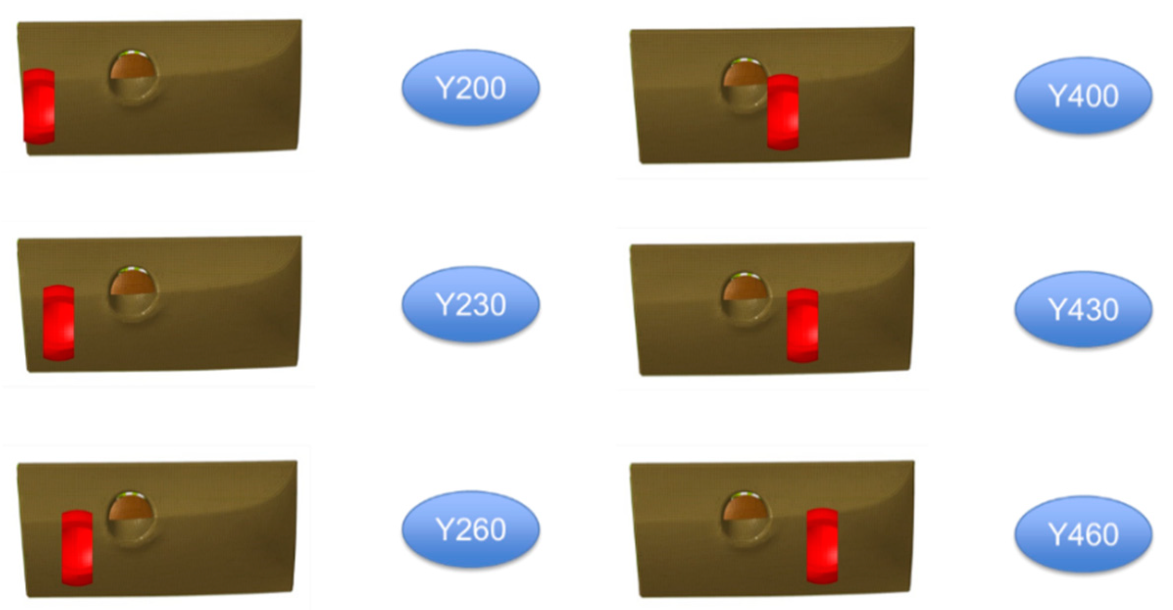
The calculation was repeated for six different positions: Y200, Y230, and Y260 for the left femur; and Y400, Y430, and Y460 for the right femur (
Figure 5). These positions covered the probable areas of contact between the knee and the glove box in the event of a frontal impact.
In Y200, the behavior of the box in PA + 5%B was worse than the current production case. This was not a concern, because it was still below the reference value.
In Y400, the PA + 5%B behaved similarly to the current case. It began to move away from the current case toward the end of the calculation, but remained below the reference value. The current case (green curve) showed a sinusoidal trend in the first section, due to the failure of an internal rib. At the moment the rib broke, a decrease in the slope of the curve was observed. The additive box had interwoven ribs and behaved as a homogeneous object. The curves passed through the mean value of the sinusoid.
In all other positions, the behavior of additive glove box was always better than the current case. Specifically, PP + 5%B had a force value that was always lower than PA + 5%B.
As a result, an optimization of the component was not necessary, since it presented better values than the current case, and was well below the reference value.
3.2. Rating Test
The subsystem test allowed the preliminary analysis of the performance of the box during a knee impact, but this was not sufficient to represent what occurs in an automobile accident. To obtain more realistic biomechanical parameters, a complete and more complex model must be used.
The objective was to fall within the range established by the Euro NCAP; therefore, the behavior of the additive box was considered acceptable, since it had the same biomechanical score as the box currently in production.
The specific test considered was the frontal impact against a deformable barrier, officially named by the Euro NCAP as the Mobile Progressive Deformable Barrier (MPDB) [
20]. The test simulated a collision between two cars of the same weight traveling at a speed of 50 km/h. The protocol prescribed the use in each front seat of a Hybrid III 50th Percentile Male Dummy (which has a size and weight greater than 50% of the American population) [
21,
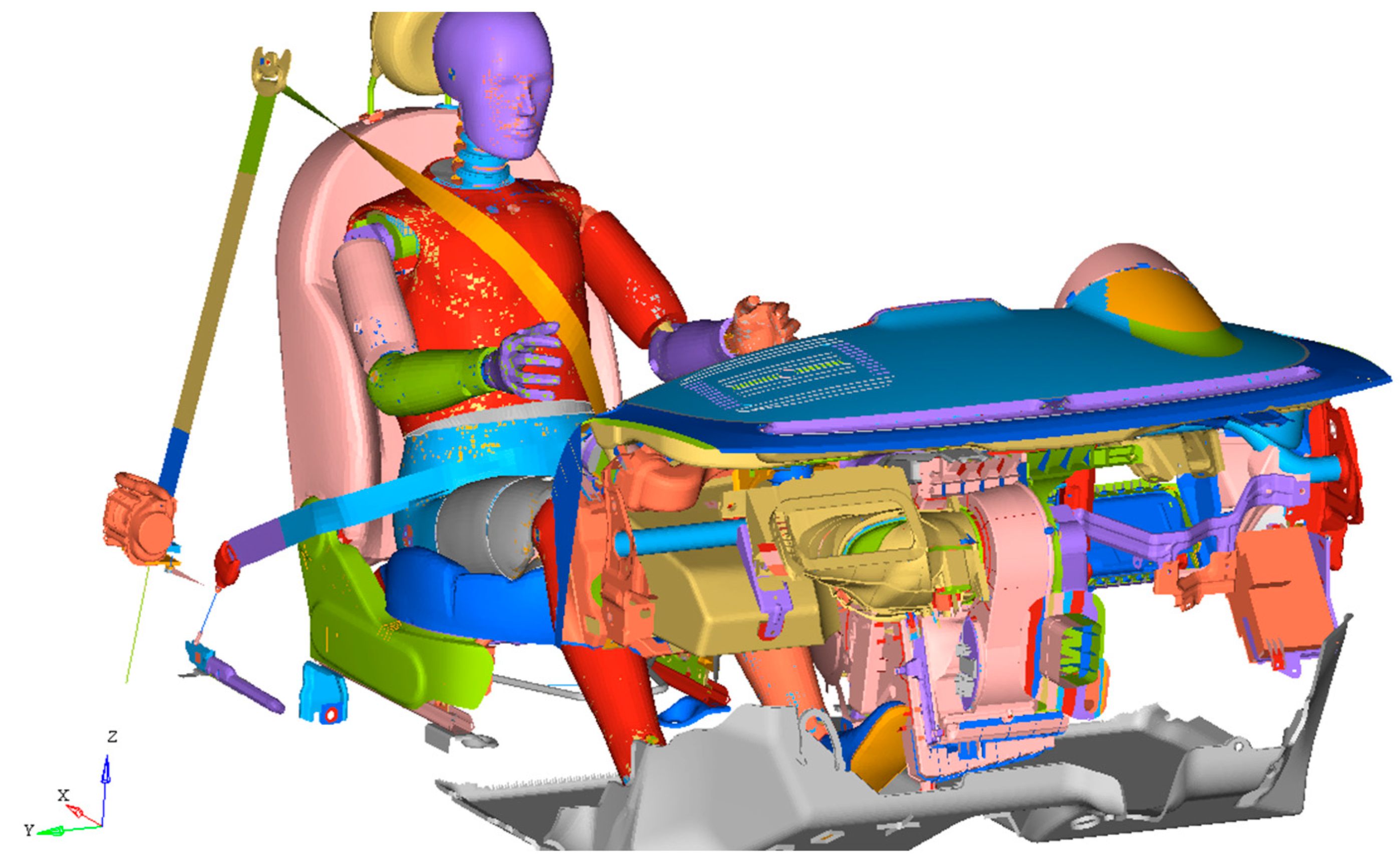
22], and two child dummies placed in the restraint systems in the rear seats. Our goal was to evaluate the biomechanical parameters of the lower limbs. Consequently, only the dashboard body and a passenger-side dummy were used instead of a full-scale model. The sled test [
23], a biomechanical test of a subsystem that reproduces the same stresses on the dummies as a full-scale impact [
24], was then carried out.
The impact phenomenon was reproduced by subjecting the constrained elements of the sled (floor, seat, and dashboard) to a rigid movement of translation in the opposite direction of the vehicle’s advancement. In this way, the dummy, due to inertial effects, was subjected to forward acceleration relative to the elements of the passenger compartment, and was consequently subjected to a loading condition similar to that of a full-scale impact. The LS-DYNA card *BOUNDARY_PRESCRIBED_MOTION_RIGID [
15] was used to impose motion. The realistic law of motion used was derived from MPDB [
20] experimental tests carried out on the same vehicle. The total number of elements was nearly 1.30 × 10
6.
The calculation times were significantly longer (nearly 6 h using 56 parallel processors) due to the complex geometry (
Figure 7).
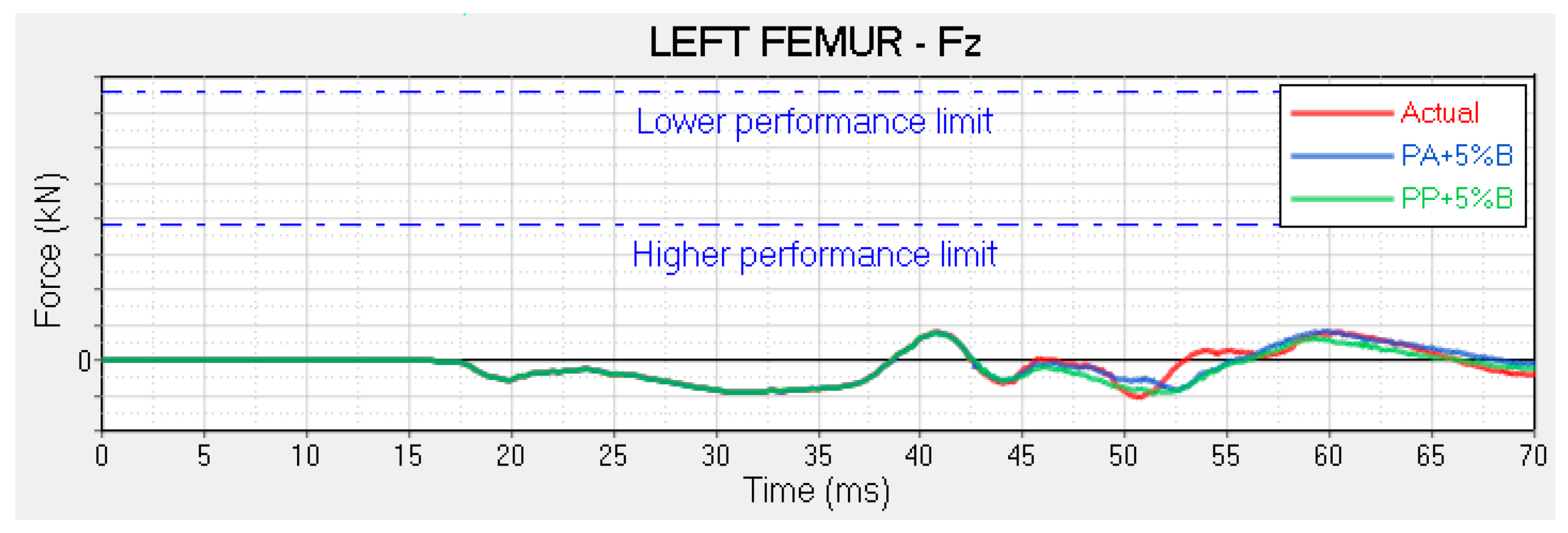
The Euro NCAP standard required, in this case, the evaluation of four parameters: compression of the femur and of the tibia, and sliding of the knee and of the tibia (obtained using the combination of moments and forces measured by the tibia load cells, Mx, My, and Fz respectively). In our specific case, femur compression and knee sliding were evaluated.
In
Figure 8, four distinct areas are noted with regard to the left femur:
t < 50 ms: The impact has not yet occurred, and there is a purely traction load. The peak at 40 ms was due to the foot’s interaction with the floor. As a result of the floor, which was simulated as rigid, there was an overestimation of the loads coming from the feet;
50 ms < t < 60 ms: The impact has occurred, and the load increases until it changes sign and provides compression;
t = 60 ms: The femur sinks completely inside the box and reaches the maximum compression load;
t > 60 ms: The load decreases due to the removal of the dashboard.
These four areas were less noticeable for the right femur (
Figure 9), because the impact between the right femur and the dashboard occurred 5 ms later than it did for the left femur, due to the geometric characteristics of the dashboard. We observed that between 55 and 65 ms, the load tended to grow, but would never switch to compression. This is because the acceleration began to decrease between 55 and 60 ms, meaning the stress on the dummy also decreased. At about 70 ms, the set speed curve assumed a horizontal slope, thus exhausting the inertial thrust action on the dummy. The right femur did not reach the maximum sinking during this time interval; consequently, the load did not switch to compression, but remained constant.
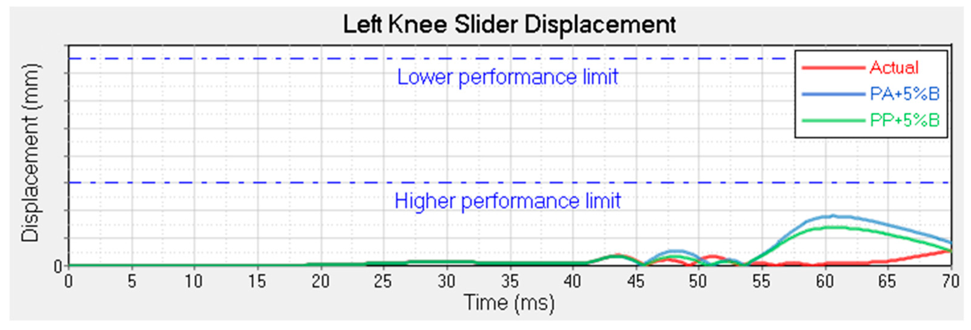
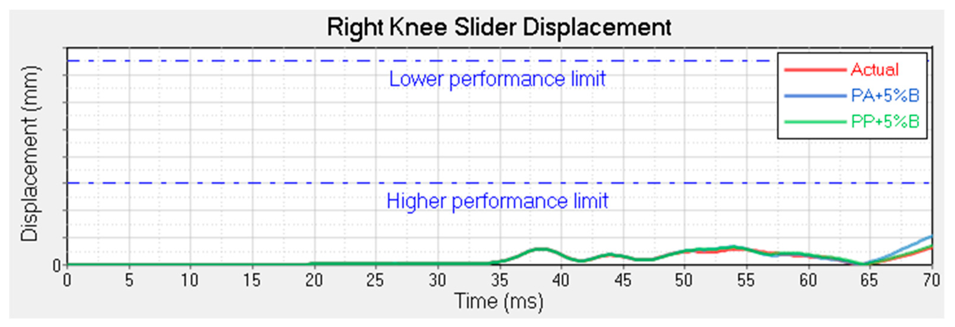
Regarding the knee sliding (
Figure 10;
Figure 11), there was a peak at around 60 ms in conjunction with the impact. Subsequent to the impact, only in the case of the sliding of the left knee, there was a worsening in performance compared to the actual case. This is explained in
Figure 12, in which the sections of the box are shown at the moment of the impact with the left leg.
In the present case, the front cover was closer to the back in the lower part of the box due to the deformation of the internal ribs, while in the upper part, the knee sunk into the cover, but not excessively, due to the presence of the ribs. In both additive boxes, we observed the opposite phenomenon. Due to the greater rigidity achieved through a higher concentration of ribs and their inclination, the overall thickness remained unchanged in the lower part, but in the upper part, the knee sunk in completely due to the absence of reinforcing ribs.
This led to an increase in the sliding of the knee in the additive case. In the upper part, the femur was free to sink into the cover and move in the −x direction; in the lower part, due to its high stiffness, there was no sinking, and the load was higher than in the current case, so the tibia was moved in the +x direction. This phenomenon is almost zero in the present case, given that the femur and tibia move solidly in the −x direction.
Therefore, regardless of the material, the more complex geometrical configuration of the additive case increased the sliding.
4. Conclusions
The adoption of a box constructed using additive manufacturing, whether PA + 5%B or PP + 5%B was used, does not lead to a worsening of biomechanical parameters compared to the current box. The structural behavior remained almost unchanged. This result may seem trivial, however, while we did not observe an improvement in structural behavior, we did observe a reduction in weight. For future applications, we can imagine using 3D printing to construct these components for premium vehicles.
Among the possible advantages for automotive industry, the following are noteworthy: warehouse cost reduction for limited-series vehicles, no tooling costs, and fast prototyping. The .stl file containing 3D-printing specifications could be sold directly to customers with a suitable 3D printer so they could independently create the component, or large distribution centers with suitable 3D printers could create the component only upon requests from customers.
One of the main goals of automobile manufacturers is to reduce the weights of their vehicles. Since 75% of fuel consumption is directly related to the weight of a vehicle, reducing weight also means reducing emissions. The mass of the PP + 5%B box is about 23% less than the current box. A car has many other plastic components that are theoretically printable in 3D. A significant reduction in weight could therefore be achieved using additive manufacturing, especially for premium cars, and cost increases resulting from the adoption of this new technology could be offset by the advantages mentioned.


