Article

Biomechanical Analysis of Two Types of Osseointegrated Transfemoral Prosthesis

by
Agostino Igor Mirulla
1,
Stefano Di Paolo
2,
Francesco Di Simone
1,
Tommaso Ingrassia
1,*,
Vincenzo Nigrelli
1,
Stefano Zaffagnini
3 and
Laura Bragonzoni
2
1
Department of Engineering, Università degli Studi di Palermo, 90128 Palermo, Italy
2
Department for Life Quality Studies, University of Bologna, Campus Rimini, 47921 Rimini, Italy
3
Clinica Ortopedica e Traumatologica II, IRCCS Istituto Ortopedico Rizzoli, via Pupilli 1, 40136 Bologna, Italy
*
Author to whom correspondence should be addressed.
Appl. Sci. 2020, 10(22), 8263; https://doi.org/10.3390/app10228263
Submission received: 30 October 2020 / Revised: 13 November 2020 / Accepted: 19 November 2020 / Published: 21 November 2020
(This article belongs to the Section Applied Biosciences and Bioengineering)

Abstract

:
In the last two decades, osseointegrated prostheses have been shown to be a good alternative for lower limb amputees experiencing complications in using a traditional socket-type prosthesis; however, restraining biomechanical issues, such as peri-prosthetic bone fractures or loosening, are present. To better understand and overcome these limiting issues, and thus reduce the number of implant failures, many studies have investigated the stress distribution on bone and implant during normal daily activities. The aim of this study was a biomechanical analysis of two different osseointegrated implants, a screw-type (OPRA) and a press fit system (OPL, Osseointegrated Prosthetic Limb), to evaluate the stresses generated in bone and prosthesis during a fall. In particular, four scenarios have been experimentally reproduced to determine the loads on the limb during different kinds of fall. For this purpose, a motion capture system and a force plate have been used. Numerical FEM (Finite Element Method) simulations have been performed to compare the behaviour of the OPRA and OPL systems in different fall scenarios. The obtained results showed that a fall backwards due to balance loss is the most stressful scenario among the ones analysed. As regards the comparison between OPRA and OPL devices, it emerged they have similar behaviours in terms of peak values of the stress, but the OPL implant generates larger high-stress areas in the distal femur as compared with the OPRA system.

1. Introduction

Two main prosthetic systems are mainly used to treat transfemoral amputees: the socket-type prosthesis and the OsseoIntegrated (OI) prosthesis. In the first case, a limb prosthesis is attached to the stump of an amputee using a socket designed to fully contain the residual limb. This approach often causes complications at the socket–stump interface mainly due to skin problems, poor fit, discomfort, sweating and poor proprioception and controllability [1]. It has been observed that complications associated with traditional socket-type prostheses can occur in more than 60% of patients [2,3].
Osseointegrated prostheses have been developed since the early 1990s [4] and thanks to their design they make it possible to overcome many complications associated with socket-fitted implants. OI prostheses, in fact, are based on osseointegration phenomena and do not require any socket. An osseointegrated prosthesis is directly attached to the skeletal system by percutaneous implant surgically inserted in the medullary canal of the residual femur [5,6] and, as a result, the artificial limb can be directly linked to the skeletal system. In particular, a stem, made of biocompatible material, is inserted into the medullary canal of the residual bone and after the healing period, during which the implant fully integrates with the bone tissue, the external prosthesis can be connected to the femur by a percutaneous abutment.
To achieve an optimal osseointegration, the most important aspects are biocompatibility, shape and surface treatment of stem, bone quality and surgical protocol, in addition to a gradual application of load [7]. After the osseointegration has occurred, the patient develops a special condition, called “osseoperception” [8]. It allows the patient to feel the weight of the prosthesis and thereby to activate the residual muscles, improving the freedom of movement of patient and thus his quality of life [9,10,11,12,13,14,15]. Patients with OI prosthesis report greater improvement of quality of life and mobility, as well as pain and infection reduction, compared to those with socket-type prosthesis [10,12,13,16,17].
Currently, two main designs are available for OI transfemoral prostheses: the screw-fixation type and the press-fit one. Both systems are composed of an intramedullary stem (fixture) and a coupling device (abutment) which passes through the soft tissues of the stump to link with the artificial limb [18,19,20]. The two systems differ in structure and composition of the intramedullary stem. A press-fit device is composed of a stem covered with a layer of highly porous metal [4,21] and achieves skeletal integration as a result of bone penetration and ingrowth [22]. A screw-type device, instead, has a threaded titanium stem that is screwed in the medullary cavity and has been developed by adapting the technology used for osseointegrated dental implants. The press-fit device is usually used only for transfemoral amputees [23]; the screw-type system, instead, is used both for transfemoral and transhumeral implants [24]. The OPRA system (Integrum, Mölndal, Sweden) is the most representative example of screw-type implants; OPL (Osseointegrated Prosthetic Limb, Permedica s.p.a., Milan, Italy) and ISP Endo/Exo prostheses (ESKA Orthopaedic Handels, Lübeck, Germany) are the most common press-fit devices. Nowadays, OPRA, ISP and OPL are the most commercially available systems for direct skeletal attachment of external limb prostheses [1].
The procedure to implant these systems consists of the same main stages. Initially, the fixture is surgically implanted into the medullary cavity. At a later stage, after a healing period during which the fixture is maintained unloaded and the bone–implant integration occurs, the abutment is connected to the fixture using a retaining bolt. The healing period varies depending on the type of implant: about 6–8 weeks for the press-fit systems and up to 6 months for the OPRA implants [25,26]. In both cases, after the fixture implantation, the bone–implant interface is irregular and consists of regions with gaps between the bone and the stem and regions of direct contact between the bone and the implant [27]. The gaps between the bone and the fixture will be later filled by compact bone thanks to bone-remodelling processes [27].
The long term success of OI implants is highly related to the mechanical loading acting on the bone and on the prosthesis during patients’ lifetime. Daily activities and unexpected critical events may produce, obviously, loadings of different kinds and magnitude that could cause failures. Two of the most common complications, in fact, are implant failures and peri-prosthetic bone fractures [4,21]. For these reasons, it is very interesting to fully understand the stress and strain distribution on the bone, the prosthesis and at the bone/fixture interface. Due to the complexity of this kind of investigation, numerical simulations are often used to assess the risks that patients can face. For several years, the Finite Element Method (FEM) has been used largely to investigate medical problems, especially in the field of orthopaedic implants [28,29,30]. Nowadays, the level of reliability and accuracy of FEM analyses is very high and, in many cases, it is comparable with that of the experimental studies [31,32].
Several studies used FEM to investigate the stress distribution on bone and implants during normal daily activities [4,25,27,33,34,35,36,37,38,39]. Nevertheless, no relevant studies in the literature have focused on the effects of critical events, such as falls, on osseointegrated transfemoral implants.
The objective of this study was twofold. Firstly, different types of falls were investigated to identify the most dangerous fall scenario, and secondly, how the stress distributions during a fall vary depending on the specific prosthetic design was investigated. Two different implants, OPRA and OPL, have been compared.

2. Materials and Methods

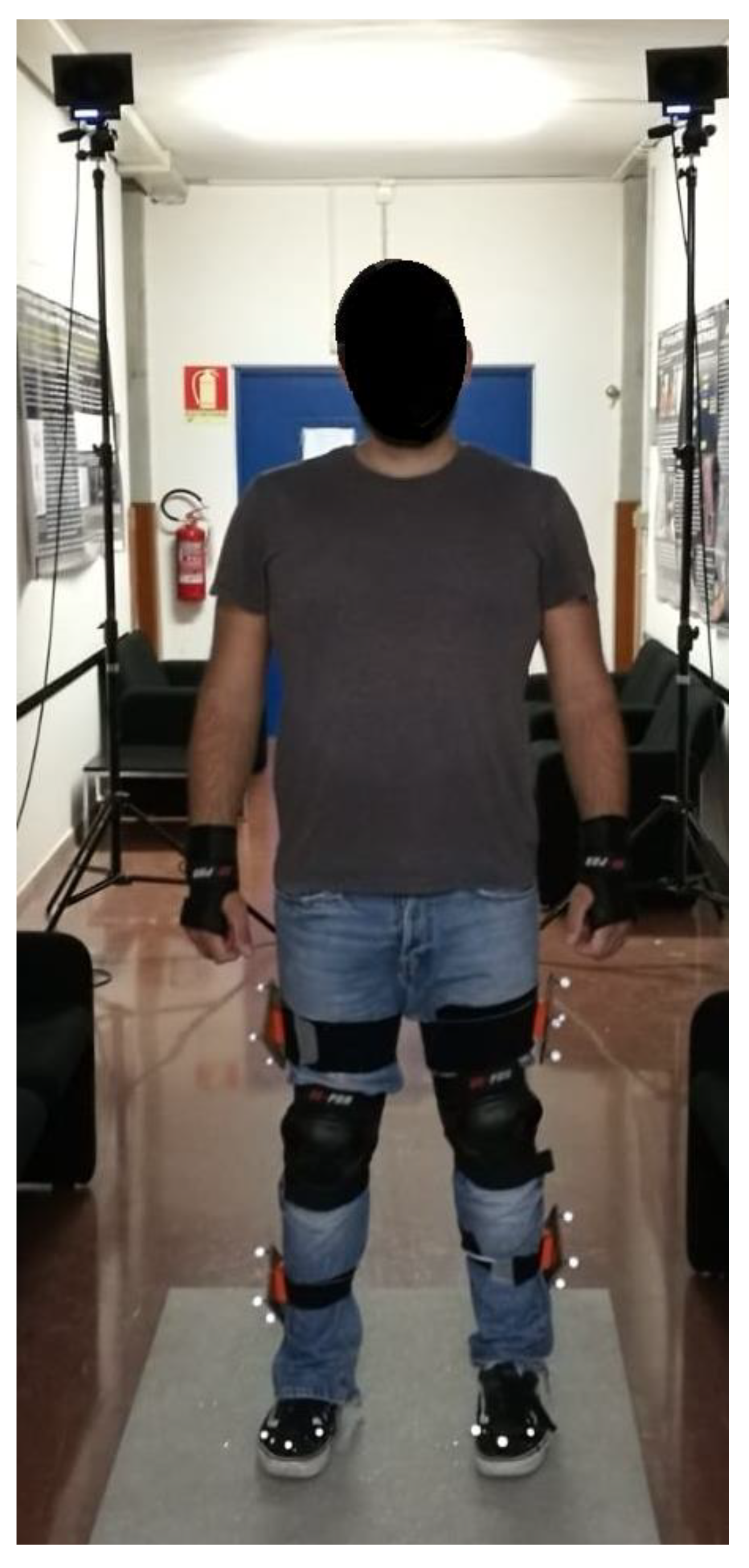
2.1. Experimental Evaluation of Loads

To experimentally evaluate the loads on the prosthetic limb during different fall scenarios, one healthy subject (male, 90 kg, 1.80 m, 31 years old) has been recruited. The subject was equipped with appropriate protections on knees, elbows and hands. The experimental tests were carried out on a wooden walkway (Figure 1) containing one force plate (P-6000, BTS Bioengineering, BTS Bioengineering, Garbagnate Milanese, Italy).
Reflective markers were placed on the subject following a custom and simplified marker protocol (Figure 2).
The markers were placed on the external side of both lower limbs to track the positions of the femurs, the tibias and the feet (Figure 3).
A 4-camera motion capture system (BTS Smart-DX, BTS Bioengineering, Garbagnate Milanese, Italy) was used to acquire marker trajectories during all tests. Marker trajectories and force data were collected at 400 Hz. Volume and static calibrations were performed according to the BTS Smart-DX guidelines before the experimental tests. Kinematic data of hip, knee and ankle along the sagittal plane were elaborated in the dedicated motion capture software (BTS Smart Tracker and BTS Smart Analyzer, BTS Bioengineering, Garbagnate Milanese, Italy) for all the falling scenarios. The position of the knee center during falls was interpolated through the BTS Smart Analyzer software, since it was not possible to place the markers on anatomical landmarks, such as epicondyles, due to knee protections. The following common fall scenarios have been investigated:
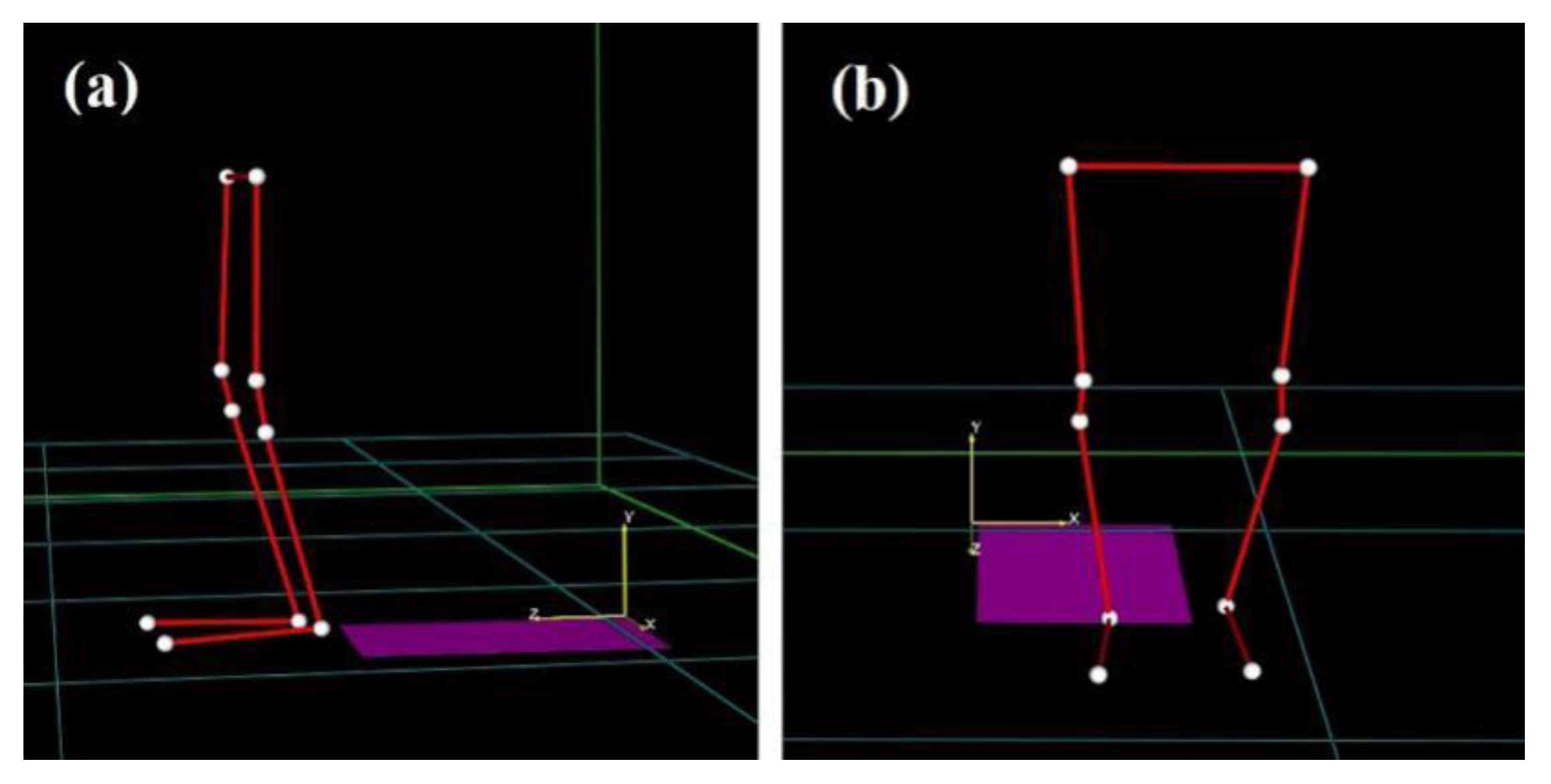
  • Fall Forward (FF): during walking, the subject falls forward and impacts both knees on the ground;
  • Fall Forward with Balance Loss (FF BL): during walking, the subject loses balance and falls forward with his hands on the ground and leans on the prosthetic limb by bending the hip and the knee;
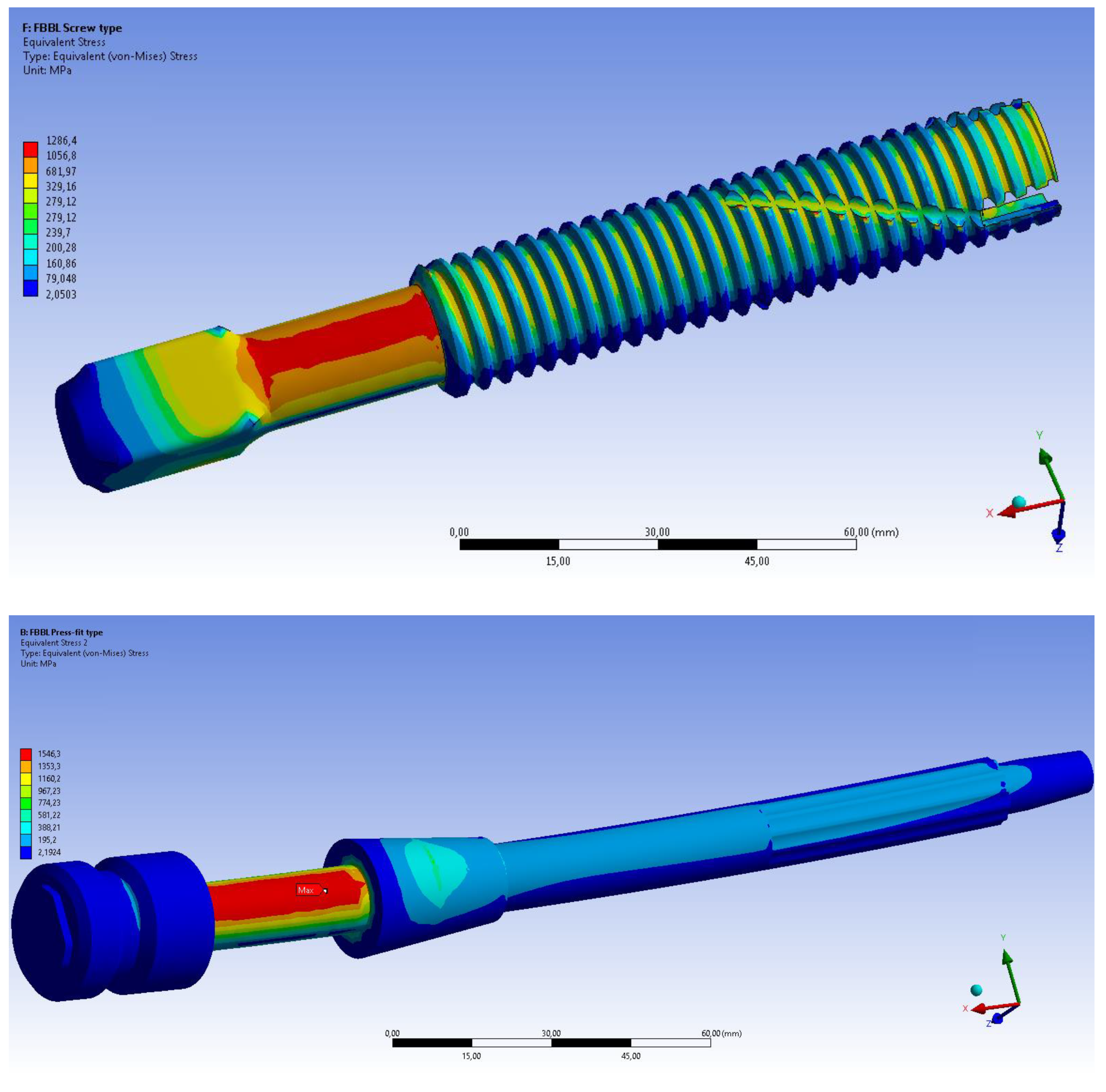
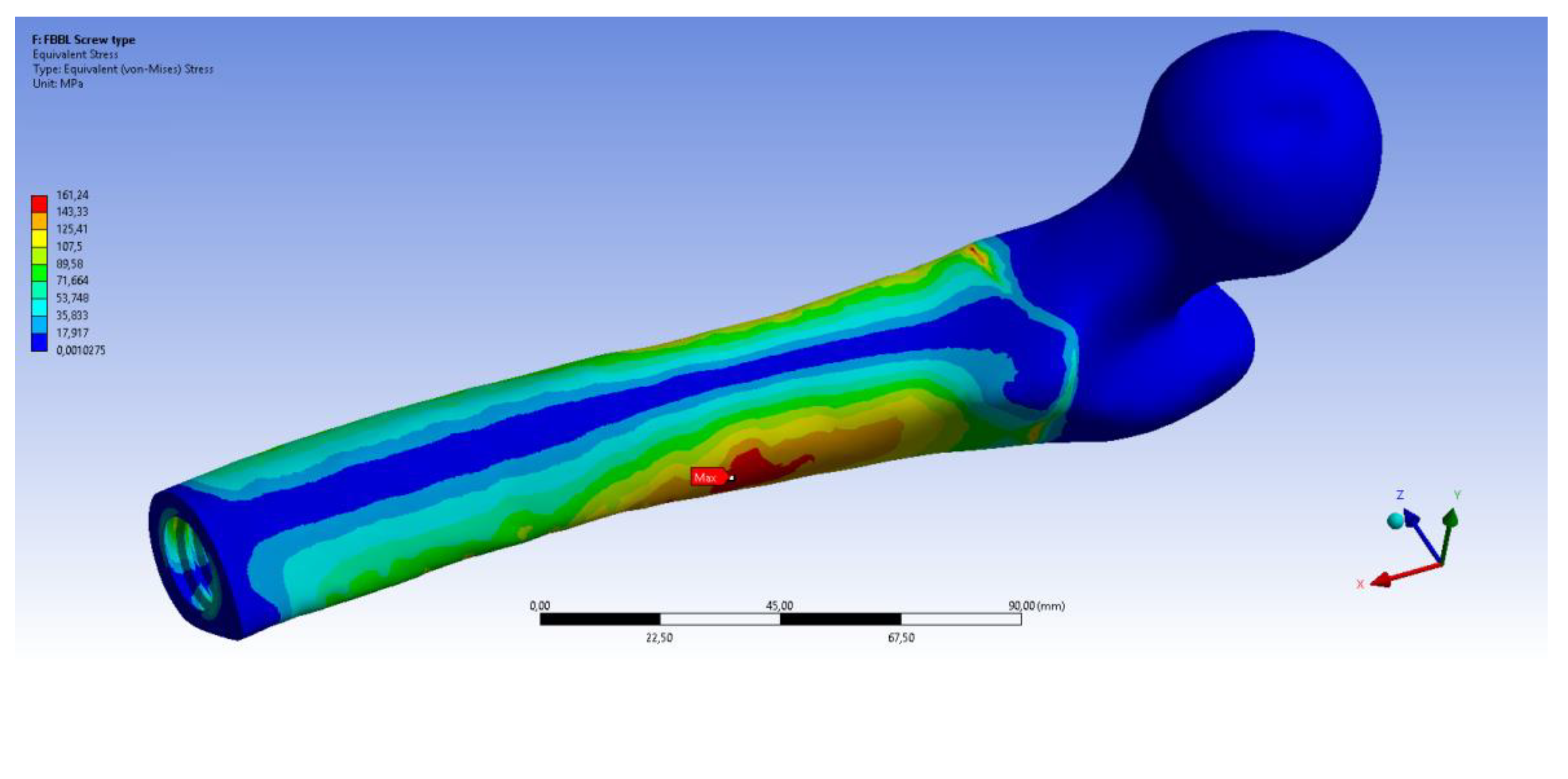
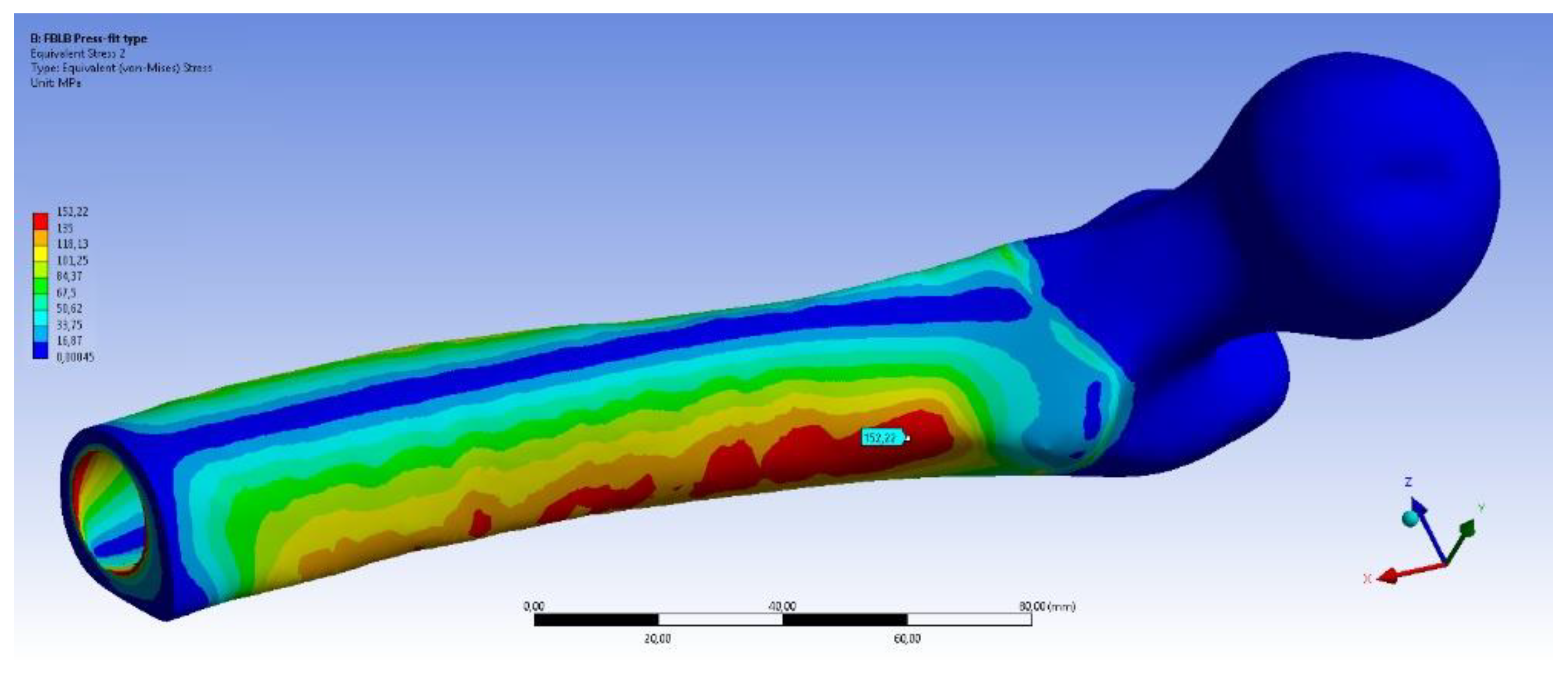
  • Fall Backwards with Balance Loss (FB BL): from an orthostatic position, the subject goes back, impacts his healthy foot against an obstacle and loses balance. To restore it, the subject extends the hip and leans on his prosthetic limb;
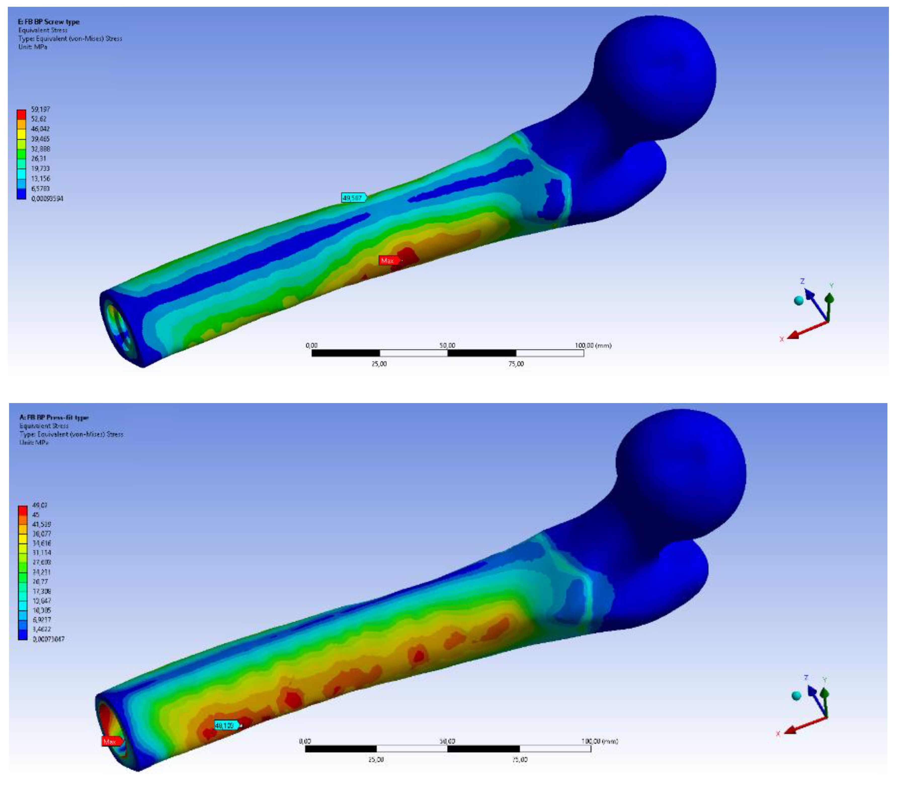
  • Fall Backwards “By Push” (FB BP): from an orthostatic position, the subject experiences a sudden push along the sagittal plane. The subject loses balance, and steps back with the contralateral limb lifted and the prosthetic limb on the ground.
The analysed fall scenarios were previously identified as typical and frequently occurring in individuals with transfemoral amputation [40]. Each type of fall was repeated 10 times to verify the repeatability of the test and the accuracy of the data collected. The measured kinematic data (positions of femur, tibia, knee and foot) were correlated with the forces measured by the force-plate during falls. In this way, after synchronizing kinematic data and measured loads, the forces and moments at the distal part of the residual femur have been evaluated through force-transfer calculations.
The schemes and reference systems used for force-transfer calculations are shown in Figure 4, where:
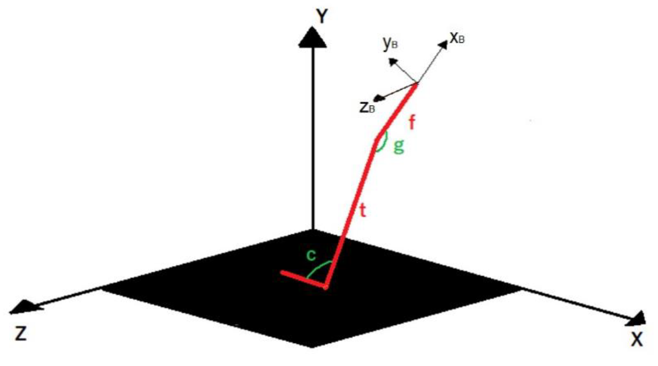
  • The lower limb is schematically represented with three uniaxial and infinitely rigid elements (red in Figure 4);
  • X-Y-Z is the reference system of the force plate;
  • xB-yB-zB is the reference system of the bone (femur);
  • t is the length of tibia;
  • f is the distance between the knee and the implant position along the femur;
  • c and g represent, respectively, the angle between foot and tibia and the angle between tibia and femur.
Calculated forces and moments have been used as boundary conditions for subsequent FEM analyses.

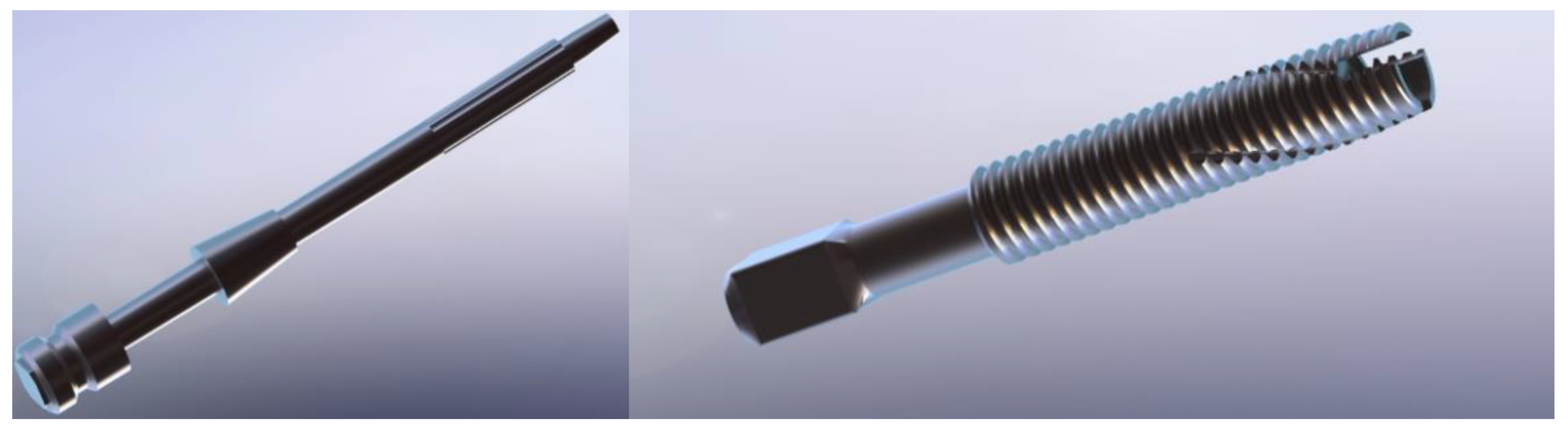
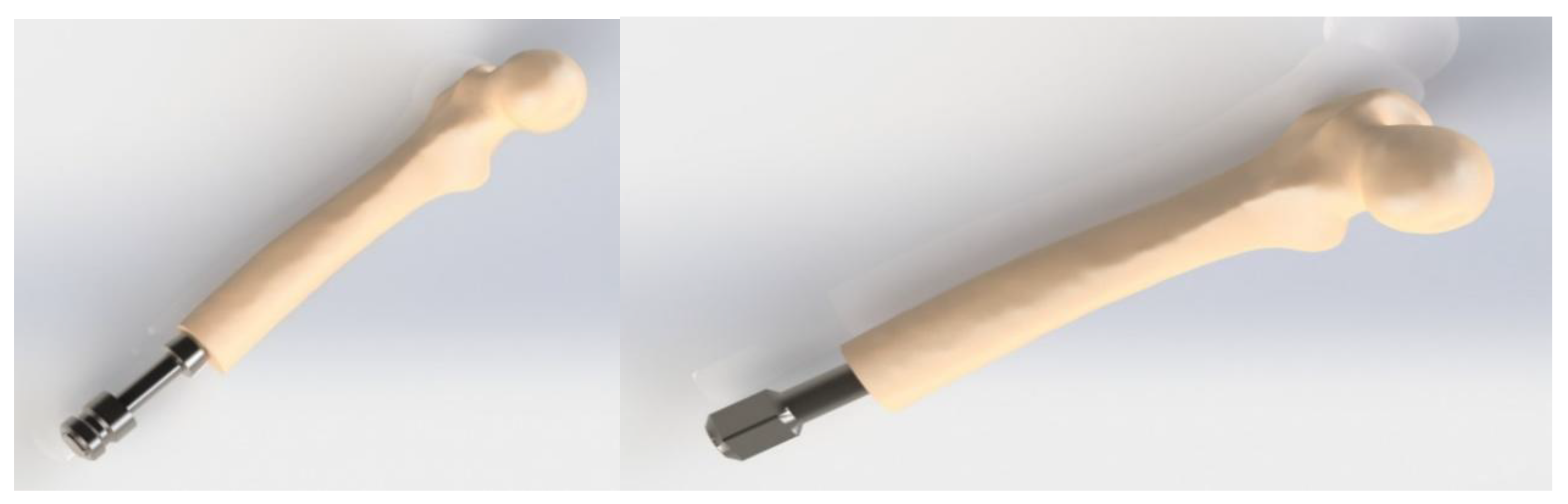
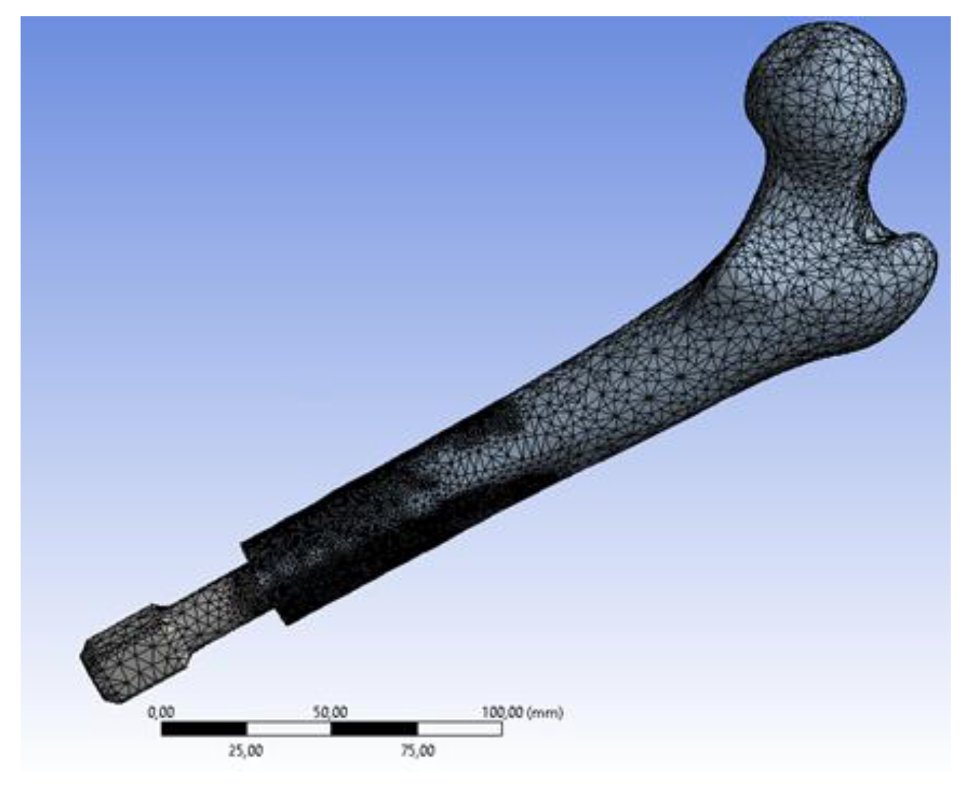
2.2. 3D CAD Modelling and FEM Model

Two different prostheses, a press-fit (OPL) and a screw type (OPRA), have been analysed. The CAD models of the prostheses (Figure 5) were created using a 3D parametric modelling software (SolidWorks, Dassault Systèmes, Vélizy-Villacoublay, France). Both models of the prostheses are composed of two main parts: an intramedullary stem (fixture) and a transcutaneous part (abutment).
The CAD model of the bone was created using DICOM images from a CT-scan of a human femur. Subsequently, the main steps of the surgical implantation of the prosthesis have been virtually reproduced by means of SolidWorks. Final CAD models of the implant/bone assemblies of both prostheses are shown in Figure 6.
Considering that, nowadays, numerical methods ensure very accurate and reliable results and are commonly used to evaluate the behaviour of orthopaedic implants [41,42,43,44,45], numerical simulations have been performed on both models to investigate how stress distributions vary during a fall. In particular, a FEM-based approach has been used and virtual simulations [24,46] have been performed using the commercial software Ansys Workbench (Ansys Inc., Canonsburg, PA, USA). To obtain highly reliable numerical models, the FEM models have been set up following a largely validated protocol [30,47,48]. Ten-node tetrahedral elements (SOLID187) were used to mesh the femur and the implant, and eight-node surface-to-surface (CONTA174 and TARGE170) contact elements [30] were used to mesh the bone/prosthesis interfaces (Figure 7).
A preliminary convergence analysis (convergence threshold value: 5%) [28,30] was performed to set the most suitable element dimension. The mesh has been refined at the interface between the intramedullary stem and the bone to improve the accuracy of the solution. The final meshes consisted of about 1,597,175 elements and 2,289,288 nodes for screw type implant, and 1,172,140 elements and 1,680,070 nodes for press-fit prothesis. Regarding the mechanical properties of the materials, the bone was considered as an orthotropic material, with the principal direction aligned along the long axis of the bone [49], while the prostheses (Ti6Al4V alloy) were considered as isotropic. The bone and the titanium alloy were considered as elastic linear hardening materials.
Table 1 and Table 2 report, respectively, the mechanical properties of the bone and of the titanium alloy Ti6Al4V. In Table 1, E1, E2, E3, G12, G13, G23, n12, n13 and n23, respectively, represent the Young’s moduli (Ei), the shear moduli (Gij) and the Poisson ratios (nij) along the radial (1), transverse (2) and longitudinal (3) directions of the cortical bone [48,50]. In Table 2, E, n and σy represent, respectively, the Young’s modulus, the Poisson’s ratio and the yield tensile stress of the titanium alloy.
According to previous studies [52,53], a bonded contact was imposed at the intramedullary stem/bone interface to simulate a total osseointegration. As for the contact algorithm, the augmented Lagrangian method was used [54]. As regards the boundary conditions, a fixed support constraint was applied to the proximal femur; the forces and the moments, calculated as described in previous Section 2.1, were applied on the end of the abutment.

2.3. Data Post Processing: Failure Analysis

To evaluate possible mechanical failures of the bone or the prosthesis, the equivalent stress values have been calculated and verified for all fall scenarios. Peak stresses, σmax, have been compared with the corresponding material strengths (S). According to [51], the strength of the bone (Sbone) has been calculated as Sbone = 114 x ρash1.72, where the ash density has been assumed to be ρash = 1.22 g/cm3, thereby obtaining Sbone = 160.5 MPa. Considering that plastic deformations could invalidate the prosthesis functionality, the yield tensile stress of the titanium alloy (σy) has been used to calculate the strength of the prosthesis (Sprosthesis = σy = 890 MPa). Bone or prosthesis failure risk was identified when σ max _ bone S bone > 1 or σ max _ prosthesis S prosthesis > 1 .
To evaluate also possible failures at the bone/implant interface, the Hoffman criterion [55] has been used. This criterion transforms the local interface stress state to a value, termed Hoffman number or H, representing the probability of interface disruption [56]. A failure is expected to occur when H > 1; for H < 1 no interface failure is expected. The Hoffman number (H) over the bone/implant interface has been calculated as [25]:
H = 1 S c S t σ n 2 + ( 1 S t 1 S c ) σ n + σ s 2 S s 2     S c = 32.4 × ρ app 1.85 S t = 14.5 × ρ app 1.71 S s = 21.6 × ρ app 1.65 ρ app = 1.79 × ρ ash + 0.0119
σ n   and   σ s are the normal (tensile) and shear stress respectively.

3. Results

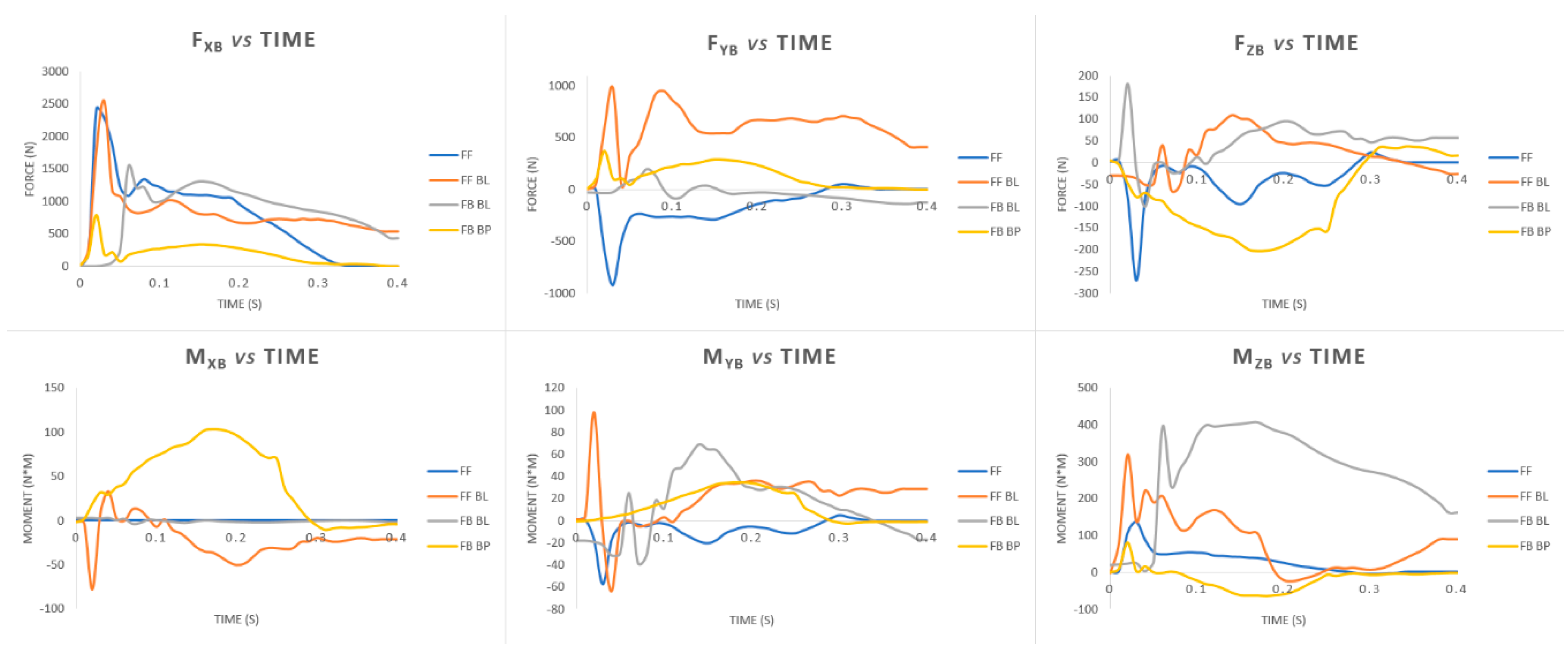
3.1. Loads during Falls
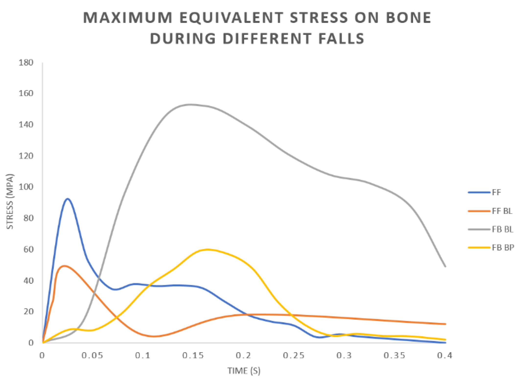
Forces and moments on the abutment have been calculated as described previously in Section 2.1. A limited time of 400 ms after the impact has been considered. The peak values of forces and moments, in fact, always occurred in this time for all analysed fall scenarios. Figure 8 shows the plots of forces/moments vs. time. The calculated loads have been used as boundary conditions for the FEM analyses.
It can be noticed that the greatest values of the forces always occur along the longitudinal axis of the femur (FxB). Two peaks of about 2500 N were calculated for the FF and FF BL fall scenarios. Regarding the moments, the highest values have been found for the anteroposterior flexion moment (MzB). A peak value of about 407 N·m has been calculated for the FB BL fall scenario.

3.2. FEM Analyses

The FEM analyses of all different fall scenarios converged at an average time of 93 ± 10 min.
Table 3 reports the peak values of the equivalent von Mises stress on the external part of the femur and on the implant.
It can be pointed out that the highest values were found for the FB BL scenario. This result agrees with the trends of the forces/moments over the time plotted in Figure 8. It is probable that very high values of the anteroposterior flexion moment (MzB) measured during the FB BL scenario (Figure 8) overstress the implant/bone assembly. Figure 9 shows the plots of the maximum values of the von Mises stress on the bone during the falls. Only the values related to the OPL system have been reported because very similar trends have been observed using the two kinds of prostheses (OPRA and OPL). From these plots it is possible to detect at what time the peak values occur and also to correlate the variations of the maximum stress values on the bone and the imposed boundary conditions (Figure 8).
In all analysed fall scenarios, both for the OPL and the OPRA system, the maximum values of the von Mises stress has been found on the abutment (Figure 10), which is always the most stressed part of the prosthesis. In the FB BL scenario, the maximum value of the von Mises stress on the prosthetic implant, both using the OPRA and the OPL implant, exceeded the ultimate tensile stress of the titanium alloy. In this condition, a failure of the abutment of the prosthesis is expected (Figure 10).
Figure 11 shows the equivalent stress distributions on femur using the OPRA and the OPL implant. It can be noticed that in both cases the maximum value of the von Mises stress is very high but, probably, no failure of the bone occurs. This is because, due to very high stresses on the prosthesis, a failure of the abutment occurs before the bone could be damaged.
Regarding the bone/implant interface, the H number, calculated through the Hoffman formula, was always lower than 1, thereby ensuring that no failure at the bone/implant interface occurs. The highest values, calculated for OPRA and OPL implants during FB BL fall scenario, are 0.58 and 0.27, respectively.

4. Discussion

Today, lower limb amputations can be treated by socket prostheses, which represent the standard of care for amputees but often are associated with significant socket–interface problems, or by osseointegrated prostheses, which involves direct attachment of the artificial limb to the skeletal residuum. Because osseointegrated limb prostheses are a fairly recent method, numerous studies have been carried out in recent years, mainly to investigate which parameters could reduce implant failures. Many studies have investigated osseointegrated implants during normal daily activities such as walking. Currently, in fact, most of the research activities have investigated the stresses’ distribution in the bone during static loading, but no relevant studies have investigated how the safety of the implantation is affected by the stresses generated during a fall.
In the present study, different fall scenarios have been investigated to experimentally determine the loads on a limb in a critical event like a fall. Subsequently, the calculated loads have been used to compare, by FEM analyses, the behaviour of two different transfemoral osseointegrated prostheses during falls, to verify if failures of bone or implant could occur. A typical screw-type implant (OPRA) and a press fit one (OPL) have been analysed.
As regards the measured loads on the limb in different fall scenarios, it was found that the most stressful configurations are the falls forward (both FF and FF BL) and the fall backwards with balance loss (FB BL), while the fall backwards “by push” has shown, on average, the lowest values of forces and moments. In particular, it was observed that:
  • Peak values of the longitudinal force occur during falls forward;
  • Very high values of the anteroposterior flexion moment on the limb occur in the FB BL fall scenario.
This last result could be justified by analysing the dynamics of this kind of fall scenario. In fact, a fall caused by loss of balance, especially if backwards, could be more unpredictable and unexpected than other types of fall (e.g., falls caused by push), during which the subject could forecast the impact. For this reason, the high bending moment calculated in the FB BL fall could be due to the unexpected loss of balance and the following extreme attempt to restore it. Moreover, this result agrees with those obtained by Schwarze et al. [57] and Welke et al. [11]. In both studies, different fall scenarios (both forward and backward) were analysed through a musculoskeletal model to determine the influence of transfemoral amputation length on the loads of OI prosthetic implants. Both studies found that fall backward scenarios are the most dangerous and, above all, the ones with highest anteroposterior moment at the level of amputation. These findings are consistent with the loads obtained experimentally in our study by motion capture. However, in [5,28] no FEM analyses were performed, so no comparison can be made in terms of stresses on bone, implant and their interface.
Regarding the comparison between OPRA and OPL implants, for all analysed falls, it emerged that peak values of the equivalent stress on the femur are always quite similar. On the other hand, sometimes very different stress distributions over the bone have been found. In particular, it was found the distal part of the residual bone is, on average, more stressed using the OPL device. This is clear when observing plots of the von Mises stress on the bone, for example in Figure 11 and Figure 12 that show the equivalent stress distributions for FB BL and FF BL scenarios.
It can be noticed that the internal areas of the distal femur are much more stressed (larger red coloured zones) when using the OPL prosthesis than the OPRA one. Moreover, it was observed that for the FB BL scenario, representing the most stressful configuration for the bone, the percentage of highly stressed volume strongly varies when comparing the two implants. In particular, it was calculated that the percentages of the volume of the bone where stress values are higher than 95% of the maximum stress are 7.2% and 2.4% for OPL and OPRA implant, respectively. All this data is interesting and should be studied in-depth for long-term successful outcomes. Stress distribution, in fact, could strongly affect the bone resorption phenomenon that often occurs using OI implants [20,58].
In terms of bone/implant interfaces, no risk of fracture exists using the Hoffman criteria.
Regarding the risk of failure, the results in Table 3 demonstrate that, during some fall scenarios, mechanical failures could occur, particularly in the prosthetic implant. However, most prosthetic implants are equipped with security/locked systems that should reduce the risk of failure on bone and prosthesis. Nevertheless, periprosthetic fractures and loosening due to very high stress values are widely reported in the literature [59,60], so the obtained results should be considered for future improvements of the design of OI prostheses.

5. Conclusions

Loads during different fall scenarios have been experimentally evaluated by a motion capture system and a force plate. Calculated loads could be effectively used for numerical analyses of different kinds of prostheses. On the basis of the obtained results, it can be stated the fall backwards with balance loss, among the scenarios analysed, is the most stressful. OPRA and OPL devices have similar behaviours during falls in terms of peak values of the equivalent stress on bone and prostheses, but OPL implant stresses the distal part of the femur more than the OPRA device. This should be considered if this kind of implant is used in poor-quality bone. Further studies should investigate design optimization of the prosthesis to further limit the risk of bone fracture and implant failure during critical events like falls, thereby improving long-term successful outcomes.

Author Contributions

Conceptualization, A.I.M., F.D.S., T.I. and L.B.; Data curation, A.I.M., F.D.S. and S.D.P.; Methodology, A.I.M., F.D.S., T.I. and L.B.; Software, A.I.M., F.D.S. and T.I.; Validation, F.D.S., T.I., L.B. and S.Z.; Supervision, T.I., V.N., L.B. and S.Z.; Writing—original draft, A.I.M., S.D.P. and T.I.; Writing—review and editing, T.I. and L.B. All authors have read and agreed to the published version of the manuscript.

Funding

This research received no external funding.

Conflicts of Interest

The authors declare no conflict of interest.

References

  1. Thesleff, A.; Brånemark, R.; Håkansson, B.; Ortiz-Catalan, M. Biomechanical Characterisation of Bone-anchored Implant Systems for Amputation Limb Prostheses: A Systematic Review. Ann. Biomed. Eng. 2018, 46, 377–391. [Google Scholar] [CrossRef] [Green Version]
  2. Robinson, D.L.; Safai, L.; Harandi, V.J.; Graf, M.; Lizama, L.E.C.; Lee, P.; Galea, M.P.; Khan, F.; Tse, K.M.; Ackland, D.C. Load response of an osseointegrated implant used in the treatment of unilateral transfemoral amputation: An early implant loosening case study. Clin. Biomech. 2020, 73, 201–212. [Google Scholar] [CrossRef]
  3. Hagberg, K.; Brånemark, R. Consequences of non-vascular trans-femoral amputation: A survey of quality of life, prosthetic use and problems. Prosthet. Orthot. Int. 2001, 25, 186–194. [Google Scholar] [CrossRef] [Green Version]
  4. Tomaszewski, P.; Van Diest, M.; Bulstra, S.; Verdonschot, N.; Verkerke, G. Numerical analysis of an osseointegrated prosthesis fixation with reduced bone failure risk and periprosthetic bone loss. J. Biomech. 2012, 45, 1875–1880. [Google Scholar] [CrossRef] [Green Version]
  5. Tomaszewski, P.; Verdonschot, N.; Bulstra, S.; Rietman, J.; Verkerke, G. Simulated bone remodeling around two types of osseointegrated implants for direct fixation of upper-leg prostheses. J. Mech. Behav. Biomed. Mater. 2012, 15, 167–175. [Google Scholar] [CrossRef] [Green Version]
  6. Jönsson, S.; Caine-Winterberger, K.; Brånemark, R. Osseointegration amputation prostheses on the upper limbs: Methods, prosthetics and rehabilitation. Prosthet. Orthot. Int. 2011, 35, 190–200. [Google Scholar] [CrossRef] [PubMed] [Green Version]
  7. Albrektsson, T.; Brånemark, P.-I.; Hansson, H.-A.; Lindström, J. Osseointegrated Titanium Implants:Requirements for Ensuring a Long-Lasting, Direct Bone-to-Implant Anchorage in Man. Acta Orthop. Scand. 1981, 52, 155–170. [Google Scholar] [CrossRef] [PubMed] [Green Version]
  8. Häggström, E.; Hagberg, K.; Rydevik, B.; Brånemark, R. Vibrotactile evaluation: Osseointegrated versus socket-suspended transfemoral prostheses. J. Rehabil. Res. Dev. 2013, 50, 1423–1434. [Google Scholar] [CrossRef] [PubMed]
  9. Brånemark, R.; Berlin, Ö.; Hagberg, K.; Bergh, P.; Gunterberg, B.; Rydevik, B. A novel osseointegrated percutaneous prosthetic system for the treatment of patients with transfemoral amputation. Bone Jt. J. 2014, 96, 106–113. [Google Scholar] [CrossRef] [PubMed] [Green Version]
  10. Sullivan, J.; Uden, M.; Robinson, K.P.; Sooriakumaran, S.; Robinson, P.K.P. Rehabilitation of the trans femoral amputee with an osseointegrated prosthesis: The United Kingdom experience. Prosthet. Orthot. Int. 2003, 27, 114–120. [Google Scholar] [CrossRef]
  11. Welke, B.; Schwarze, M.; Hurschler, C.; Calliess, T.; Seehaus, F. Multi-body simulation of various falling scenarios for determining resulting loads at the prosthesis interface of transfemoral amputees with osseointegrated fixation. J. Orthop. Res. 2013, 31, 1123–1129. [Google Scholar] [CrossRef] [PubMed]
  12. Van De Meent, H.; Hopman, M.T.; Frölke, J.P. Walking Ability and Quality of Life in Subjects With Transfemoral Amputation: A Comparison of Osseointegration With Socket Prostheses. Arch. Phys. Med. Rehabil. 2013, 94, 2174–2178. [Google Scholar] [CrossRef] [PubMed]
  13. Leijendekkers, R.A.; Van Hinte, G.; Frölke, J.P.; Van De Meent, H.; Der Sanden, M.W.N.-V.; Staal, J.B. Comparison of bone-anchored prostheses and socket prostheses for patients with a lower extremity amputation: A systematic review. Disabil. Rehabil. 2016, 39, 1045–1058. [Google Scholar] [CrossRef] [PubMed] [Green Version]
  14. Al Muderis, M.M.; Lu, W.Y.; Li, J.J.; Kaufman, K.R.; Orendurff, M.; Highsmith, M.J.; Lunseth, P.A.; Kahle, J.T. Clinically Relevant Outcome Measures Following Limb Osseointegration; Systematic Review of the Literature. J. Orthop. Trauma 2018, 32, e64–e75. [Google Scholar] [CrossRef]
  15. Shelton, T.J.; Beck, J.P.; Bloebaum, R.D.; Bachus, K.N. Percutaneous osseointegrated prostheses for amputees: Limb compensation in a 12-month ovine model. J. Biomech. 2011, 44, 2601–2606. [Google Scholar] [CrossRef] [Green Version]
  16. Leijendekkers, R.A.; Van Hinte, G.; Der Sanden, M.W.N.-V.; Staal, J.B. Gait rehabilitation for a patient with an osseointegrated prosthesis following transfemoral amputation. Physiother. Theory Pract. 2017, 33, 147–161. [Google Scholar] [CrossRef] [Green Version]
  17. Aschoff, A.H.H.; Clausen, A.; Hoffmeister, T. The Endo-Exo Femur Prosthesis—A New Concept of Bone-Guided, Prosthetic Rehabilitation Following Above-Knee Amputation. Z. Orthop. Unfallchir. 2009, 8, 610–615. [Google Scholar] [CrossRef]
  18. Brånemark, R.; I Brånemark, P.; Rydevik, B.; Myers, R.R. Osseointegration in skeletal reconstruction and rehabilitation: A review. J. Rehabil. Res. Dev. 2001, 38, 175–181. [Google Scholar]
  19. Nebergall, A.; Bragdon, C.; Antonellis, A.; Kärrholm, J.; Brånemark, R.; Malchau, H. Stable fixation of an osseointegated implant system for above-the-knee amputees: Titel RSA and radiographic evaluation of migration and bone remodeling in 55 cases. Acta Orthop. 2012, 83, 121–128. [Google Scholar] [CrossRef]
  20. Hagberg, K.; Brånemark, R.; Stråket, B. One hundred patients treated with osseointegrated transfemoral amputation prostheses—Rehabilitation perspective. J. Rehabil. Res. Dev. 2009, 46, 331–344. [Google Scholar] [CrossRef]
  21. Aschoff, H.H.; Kennon, R.E.; Keggi, J.M.; Rubin, L.E. Transcutaneous, Distal Femoral, Intramedullary Attachment for Above-the-Knee Prostheses: An Endo-Exo Device. J. Bone Jt. Surg. 2010, 92, 180–186. [Google Scholar] [CrossRef] [PubMed]
  22. Al Muderis, M.; Lu, W.; Li, J.J. Osseointegrated Prosthetic Limb for the treatment of lower limb amputations: Experience and outcomes. Der Unfallchirurg 2017, 120, 306–311. [Google Scholar] [CrossRef] [PubMed]
  23. Frölke, J.P.M.; Leijendekkers, R.A.; Van De Meent, H. Osseointegrated prosthesis for patients with an amputation Multidisciplinary team approach in the Netherlands. Der Unfallchirurg 2017, 120, 293–299. [Google Scholar] [CrossRef] [PubMed] [Green Version]
  24. Mirulla, A.; Bragonzoni, L.; Zaffagnini, S.; Bontempi, M.; Nigrelli, V.; Ingrassia, T. Virtual simulation of an osseointegrated trans-humeral prosthesis: A falling scenario. Injury 2018, 49, 784–791. [Google Scholar] [CrossRef] [PubMed]
  25. Tomaszewski, P.K.; Verdonschot, N.; Bulstra, S.K.; Verkerke, G.J. A Comparative Finite-Element Analysis of Bone Failure and Load Transfer of Osseointegrated Prostheses Fixations. Ann. Biomed. Eng. 2010, 38, 2418–2427. [Google Scholar] [CrossRef] [Green Version]
  26. Prochor, P. Finite element analysis of stresses generated in cortical bone during implantation of a novel Limb Prosthesis Osseointegrated Fixation System. Biocybern. Biomed. Eng. 2017, 37, 255–262. [Google Scholar] [CrossRef]
  27. Lee, W.C.; Doocey, J.M.; Brånemark, R.; Adam, C.J.; Evans, J.H.; Pearcy, M.J.; Frossard, L.A. FE stress analysis of the interface between the bone and an osseointegrated implant for amputees—Implications to refine the rehabilitation program. Clin. Biomech. 2008, 23, 1243–1250. [Google Scholar] [CrossRef]
  28. Cerniglia, D.; Ingrassia, T.; D’Acquisto, L.; Saporito, M.; Tumino, D. Contact between the components of a knee prosthesis: Numerical and experimental study. Frattura ed Integrità Strutturale 2012, 6, 56–68. [Google Scholar] [CrossRef] [Green Version]
  29. Chen, F.; Huang, X.; Ya, Y.; Ma, F.; Qian, Z.; Shi, J.; Guo, S.; Yu, B. Finite element analysis of intramedullary nailing and double locking plate for treating extra-articular proximal tibial fractures. J. Orthop. Surg. Res. 2018, 13, 12. [Google Scholar] [CrossRef] [Green Version]
  30. Ingrassia, T.; Nigrelli, V.; Pecorella, D.; Bragonzoni, L.; Ricotta, V. Influence of the Screw Positioning on the Stability of Locking Plate for Proximal Tibial Fractures: A Numerical Approach. Appl. Sci. 2020, 10, 4941. [Google Scholar] [CrossRef]
  31. Anderson, D.D.; Thomas, T.P.; Marin, A.C.; Elkins, J.M.; Lack, W.D.; Lacroix, D. Computational techniques for the assessment of fracture repair. Injury 2014, 45, S23–S31. [Google Scholar] [CrossRef] [PubMed] [Green Version]
  32. Tumino, D.; Ingrassia, T.; Nigrelli, V.; Pitarresi, G.; Miano, V.U. Mechanical behavior of a sandwich with corrugated GRP core: Numerical modeling and experimental validation. Frattura ed Integrità Strutturale 2014, 8, 317–326. [Google Scholar] [CrossRef] [Green Version]
  33. Dickinson, A.S.; Steer, J.W.; Worsley, P.R. Finite element analysis of the amputated lower limb: A systematic review and recommendations. Med. Eng. Phys. 2017, 43, 1–18. [Google Scholar] [CrossRef] [PubMed]
  34. Helgason, B.; Pálsson, H.; Rúnarsson, T.P.; Frossard, L.; Viceconti, M. Risk of failure during gait for direct skeletal attachment of a femoral prosthesis: A finite element study. Med. Eng. Phys. 2009, 31, 595–600. [Google Scholar] [CrossRef] [Green Version]
  35. Newcombe, L.; Dewar, M.; Blunn, G.; Fromme, P. Effect of amputation level on the stress transferred to the femur by an artificial limb directly attached to the bone. Med. Eng. Phys. 2013, 35, 1744–1753. [Google Scholar] [CrossRef]
  36. Tomaszewski, P.; Lasnier, B.; Hannink, G.; Verkerke, G.J.; Verdonschot, N. Experimental assessment of a new direct fixation implant for artificial limbs. J. Mech. Behav. Biomed. Mater. 2013, 21, 77–85. [Google Scholar] [CrossRef]
  37. Xu, W.; Crocombe, A.D.; Hughes, S.C. Finite element analysis of bone stress and strain around a distal osseointegrated implant for prosthetic limb attachment. Proc. Inst. Mech. Eng. Part H J. Eng. Med. 2000, 214, 595–602. [Google Scholar] [CrossRef]
  38. Xu, W.; Xu, D.H.; Crocombe, A.D. Three-dimensional finite element stress and strain analysis of a transfemoral osseointegration implant. Proc. Inst. Mech. Eng. Part H J. Eng. Med. 2006, 220, 661–670. [Google Scholar] [CrossRef]
  39. Zheng, L.; Luo, J.; Yang, B.C.; Chen, J.Y.; Zhang, X.D. 3D Finite Element Analysis of Bone Stress around Distally Osteointegrated Implant for Artificial Limb Attachment. Key Eng. Mater. 2005, 288, 653–656. [Google Scholar] [CrossRef]
  40. Blumentritt, S.; Schmalz, T.; Jarasch, R. The Safety of C-Leg: Biomechanical Tests. JPO J. Prosthet. Orthot. 2009, 21, 2–15. [Google Scholar] [CrossRef]
  41. Ingrassia, T.; Nalbone, L.; Nigrelli, V.; Pisciotta, D.; Ricotta, V. Influence of the metaphysis positioning in a new reverse shoulder prosthesis. Lect. Notes Mech. Eng. 2017, 469–478. [Google Scholar]
  42. Chen, P.; Lü, H.; Shen, H.; Wang, W.; Ni, B.; Chen, J. Newly designed anterolateral and posterolateral locking anatomic plates for lateral tibial plateau fractures: A finite element study. J. Orthop. Surg. Res. 2017, 12, 35. [Google Scholar] [CrossRef] [PubMed] [Green Version]
  43. Ingrassia, T.; Nigrelli, V.; Ricotta, V.; Nalbone, L.; D’Arienzo, A.; Porcellini, G.; D’Arienzo, M. A new method to evaluate the influence of the glenosphere positioning on stability and range of motion of a reverse shoulder prosthesis. Injury 2019, 50, S12–S17. [Google Scholar] [CrossRef] [PubMed]
  44. Ingrassia, T.; Nalbone, L.; Nigrelli, V.; Ricotta, V.; Pisciotta, D. Biomechanical analysis of the humeral tray positioning in reverse shoulder arthroplasty design. Int. J. Interact. Des. Manuf. 2018, 12, 651–661. [Google Scholar] [CrossRef]
  45. Inzana, J.A.; Varga, P.; Windolf, M. Implicit modeling of screw threads for efficient finite element analysis of complex bone-implant systems. J. Biomech. 2016, 49, 1836–1844. [Google Scholar] [CrossRef] [PubMed]
  46. Cirello, A.; Cucinotta, F.; Ingrassia, T.; Nigrelli, V.; Sfravara, F. Fluid–structure interaction of downwind sails: A new computational method. J. Mar. Sci. Technol. 2019, 24, 86–97. [Google Scholar] [CrossRef]
  47. Jacquet, C.; Marret, A.; Myon, R.; Ehlinger, M.; Bahlouli, N.; Wilson, A.; Kley, K.; Rossi, J.-M.; Parratte, S.; Ollivier, M. Adding a protective screw improves hinge’s axial and torsional stability in High Tibial Osteotomy. Clin. Biomech. 2020, 74, 96–102. [Google Scholar] [CrossRef]
  48. Ji, W.; Luo, C.F.; Zhan, S.; Zhan, Y.; Xie, X.; Zhang, B. Combined proximal tibial osteotomy for varus osteoarthritis of the knee: Biomechanical tests and finite-element analyses. Knee 2020, 27, 863–870. [Google Scholar] [CrossRef]
  49. Perez, A.; Mahar, A.; Negus, C.; Newton, P.; Impelluso, T. A computational evaluation of the effect of intramedullary nail material properties on the stabilization of simulated femoral shaft fractures. Med. Eng. Phys. 2008, 30, 755–760. [Google Scholar] [CrossRef]
  50. Ingrassia, T.; Lombardo, B.; Nigrelli, V.; Ricotta, V.; Nalbone, L.; D’Arienzo, A.; D’Arienzo, M.; Porcellini, G. Influence of sutures configuration on the strength of tendon-patch joints for rotator cuff tears treatment. Injury 2019, 50, S18–S23. [Google Scholar] [CrossRef]
  51. Keyak, J.; Falkinstein, Y. Comparison of in situ and in vitro CT scan-based finite element model predictions of proximal femoral fracture load. Med. Eng. Phys. 2003, 25, 781–787. [Google Scholar] [CrossRef]
  52. Anwar, A.; Lv, D.; Zhao, Z.; Zhang, Z.; Lu, M.; Nazir, M.U.; Qasim, W. Finite element analysis of the three different posterior malleolus fixation strategies in relation to different fracture sizes. Injury 2017, 48, 825–832. [Google Scholar] [CrossRef] [PubMed]
  53. Chen, Y.-N.; Chang, C.-W.; Li, C.-T.; Chen, C.-H.; Chung, C.-R.; Peng, Y.-T. Biomechanical investigation of the type and configuration of screws used in high tibial osteotomy with titanium locking plate and screw fixation. J. Orthop. Surg. Res. 2019, 14, 1–8. [Google Scholar] [CrossRef] [PubMed]
  54. Simo, J.; Laursen, T. An augmented lagrangian treatment of contact problems involving friction. Comput. Struct. 1992, 42, 97–116. [Google Scholar] [CrossRef]
  55. Hoffman, O. The Brittle Strength of Orthotropic Materials. J. Compos. Mater. 1967, 1, 200–206. [Google Scholar] [CrossRef]
  56. Van Rietbergen, B.B.; Huiskes, H.R. Load transfer and stress shielding of the hydroxyapatite-ABG hip: A study of stem length and proximal fixation. J. Arthroplast. 2001, 16 (Suppl. 1), 55–63. [Google Scholar] [CrossRef]
  57. Schwarze, M.; Hurschler, C.; Seehaus, F.; Correa, T.A.; Welke, B. Influence of transfemoral amputation length on resulting loads at the osseointegrated prosthesis fixation during walking and falling. Clin. Biomech. 2014, 29, 272–276. [Google Scholar] [CrossRef]
  58. Stenlund, P.; Trobos, M.; Lausmaa, J.; Brånemark, R.; Thomsen, P.; Palmquist, A. Effect of load on the bone around bone-anchored amputation prostheses. J. Orthop. Res. 2017, 35, 1113–1122. [Google Scholar] [CrossRef] [Green Version]
  59. Tsikandylakis, G.; Berlin, Ö.; Brånemark, R. Implant Survival, Adverse Events, and Bone Remodeling of Osseointegrated Percutaneous Implants for Transhumeral Amputees. Clin. Orthop. Relat. Res. 2014, 472, 2947–2956. [Google Scholar] [CrossRef] [Green Version]
  60. Van Eck, C.F.; McGough, R.L. Clinical outcome of osseointegrated prostheses for lower extremity amputations: A systematic review of the literature. Curr. Orthop. Pract. 2015, 26, 349–357. [Google Scholar] [CrossRef]
Figure 1. Experimental setup for load acquisition: wooden walkway and force plate.
Applsci 10 08263 g001
Figure 2. Marker-set protocol for motion capture data acquisition: side view (a) and front view (b).
Applsci 10 08263 g002
Figure 3. Subject equipped with protections and reflective markers for motion capture.
Applsci 10 08263 g003
Figure 4. Schemes and reference systems used to calculate loads at the bone/implant interface.
Applsci 10 08263 g004
Figure 5. CAD models of the prosthetic implants analysed: OPL (on the left) and OPRA (on the right).
Applsci 10 08263 g005
Figure 6. CAD models of the implant/bone assemblies: OPL (on the left) and OPRA (on the right).
Applsci 10 08263 g006
Figure 7. Meshed model (screw type prosthesis).
Applsci 10 08263 g007
Figure 8. Plots of forces and moments vs. time calculated for different fall scenarios: Fall Forward (FF), Fall Forward with Balance Loss (FF BL), Fall Backwards with Balance Loss (FB BL), Fall Backwards “By Push” (FB BP).
Applsci 10 08263 g008
Figure 9. OPL prosthesis: Plots of the maximum values of the equivalent stress on the bone during different fall scenarios: Fall Forward (FF), Fall Forward with Balance Loss (FF BL), Fall Backwards with Balance Loss (FB BL), Fall Backwards “By Push” (FB BP).
Applsci 10 08263 g009
Figure 10. Fall Backwards with Balance Loss (FB BL) scenario: von Mises stress distribution on the OPRA (top) and the OPL (bottom) prosthesis.
Applsci 10 08263 g010
Figure 11. Fall Backwards with Balance Loss (FB BL) scenario: von Mises stress distribution on femur using the OPRA (top) and the OPL (bottom) device.
Applsci 10 08263 g011aApplsci 10 08263 g011b
Figure 12. Fall Forward with Balance Loss (FF BL) scenario: von Mises stress distribution on femur using the OPRA (top) and the OPL (bottom) device.
Applsci 10 08263 g012
Table 1. Main mechanical properties of the cortical bone [51].
E1 (GPa)E2 (GPa)E3 (GPa)G12 (GPa)G13 (GPa)G23 (GPa)n12n13n23
6.918.5118.42.413.564.910.490.120.14
Table 2. Main mechanical properties of the titanium alloy Ti6Al4V [30].
MaterialE (GPa)nσy (MPa)
Ti6Al4V1150.33890
Table 3. Peak values of the equivalent stress (MPa) calculated for different fall scenarios: Fall Forward (FF), Fall Forward with Balance Loss (FF BL), Fall Backwards with Balance Loss (FB BL), Fall Backwards “By Push” (FB BP).
FemurImplant
Screw-TypePress FitScrew-TypePress Fit
FF9391607723
FF BL5949913855
FB BL16115212861546
FB BP6359602557
Publisher’s Note: MDPI stays neutral with regard to jurisdictional claims in published maps and institutional affiliations.

