Article

Airfoil Aerodynamics in Proximity to Wavy Ground for a Wide Range of Angles of Attack

School of Aeronautical Science and Engineering, Beihang University, Beijing 100191, China
*
Author to whom correspondence should be addressed.
Appl. Sci. 2020, 10(19), 6773; https://doi.org/10.3390/app10196773
Submission received: 19 August 2020 / Revised: 22 September 2020 / Accepted: 24 September 2020 / Published: 27 September 2020
(This article belongs to the Section Aerospace Science and Engineering)

Abstract

:

Featured Application

This study is meaningful for the design and safe flight of the wing-in-ground craft.

Abstract

Wing-in-ground craft often encounter waves when flying over the sea surface, and the ground effect is more complicated than that of flat ground. Therefore, the aerodynamic characteristics of the NACA 4412 airfoil in proximity to wavy ground for a wide range of angles of attack is studied by solving the Reynolds Averaged Navier–Stokes equations. The validation of the numerical method is carried out by comparing it with the experimental data. The results show that the aerodynamic coefficients will fluctuate periodically when the airfoil moves over wavy ground at a small ride height. Except for the angle of attack of 0°, the fluctuation trend of aerodynamic coefficients at other angles of attack is the same. The analysis of aerodynamic fluctuation amplitude found that the medium angle of attack should be selected as the design cruise angle of attack for wing-in-ground craft. The time-averaged aerodynamic coefficients in the case of wavy ground are almost the same as those of flat ground. Hence, wavy ground mainly causes a fluctuation in aerodynamic coefficients. Considering the difference between aerodynamic coefficients at the angle of attack of 0° and at other angles of attack, the flow field structure at an angle of attack of 0° and 4° is analyzed. The results reveal the aerodynamic characteristics of the airfoil moving over wavy ground, which gives a deeper understanding of the ground effect in the conditions of wavy surface/ground. This has a certain guiding significance for the design of wing-in-ground craft.

1. Introduction

The wing-in-ground (WIG) craft [1] is a kind of aircraft that makes full use of ground effect at low altitudes to improve flight efficiency. It is mainly used for high-speed water transportation. Compared with ships, it has the advantages of fast speed and low resistance; compared with aircrafts, it has the advantages of a high lift-to-drag ratio and a high energy utilization efficiency. However, the WIG craft has unique aerodynamic characteristics when flying near to the ground which are significantly different from those of conventional aircraft. Therefore, many scholars have carried out research on the unique aerodynamic characteristics of the WIG craft [2,3,4,5,6,7,8].
The WIG craft is designed to fly at a low altitude, but there are various obstacles such as buildings, trees, hills, and other obstacles on the land. The vast ocean is flat, which provides a good application scenario for the WIG craft flying at a low altitude. Therefore, most WIG crafts are used for water transportation. Up to present, most of the researchers focusing on the ground effect assume that the ground is flat. However, there are often waves on the water surface. Therefore, it is necessary to study the ground effect under wavy ground conditions.
Hsiun [3] studied the aerodynamic characteristics of the airfoil in ground effect by solving the steady Reynolds Averaged Navier–Stokes equations (RANS). He found that ground clearance had a significant impact on the lift coefficient, and when the ground clearance was less than a specific value, the lift would be lost. Ocken [8] applied the numerical method to study the aerodynamic characteristics of the airfoil with a deflection flap in ground effect. Yang [9] carried out numerical simulations on WIG craft with a power-augmented ram (PAR) engine. Jamei [4] numerically investigated the aerodynamic characteristics of compound wings with the ground effect. He concluded that, compared with the rectangular wing, the compound wing had greater lift, less drag, and better aerodynamic characteristics, especially in the case of small ground clearance. Qu [10] investigated the aerodynamics and flow physics of a NACA4412 airfoil with ground effect for a wide range of angles of attack; his research showed that the angle of attack (AOA) versus ride height plane could be divided into three regions based on the sign of the lift increment value. Besides this, Qu [11] also studied the aerodynamic properties of the dynamic ground effect (DGE), supposing that the distance between an aircraft and the ground keeps constantly changing during takeoff and landing. These studies all assume that the ground is a rigid flat ground, and preliminary studies of the ground effect are carried out on this basis.
Different from the ground covered with obstacles, such as trees, buildings, hills, and so on, the flatness of the sea surface provides a good flying environment for WIG crafts, therefore this kind of aircraft is mainly used for high-speed transportation along the water surface. However, the actual sea surface is a free surface. To get closer to reality, some scholars begin to employ free surface instead of rigid ground to study the ground effect. Barber [12] studied the water surface deformation when the wing moved over a free surface at a small ride height; her results showed that any deformation occurring on the water surface was likely to be caused by the wingtip vortices rather than an increased pressure distribution beneath the wing. With the increase in velocity, the deformation of the water surface became less significant. Jung [6] numerically investigated the effect of an endplate on the 3-D WIG problem using the assumptions of steady incompressible viscous flow. He found that endplate could effectively increase lift and reduce drag with the ground effect, and the wingtip vortex will cause a small deformation of the water surface. Zong and Liang [13,14] applied the lifting line theory to study the ground effect of a three-dimensional wing near the free surface. Their results showed that the deformation of the free surface was significant at a low velocity, and that the lift coefficient fluctuates dramatically; at a high velocity, the deformation of the free surface could be neglected so that the free surface could be represented by a rigid wall. Bal [15] developed the iterative boundary element method to investigate the effects of free surface both on 2-D airfoils and 3-D wings moving over a free surface. He concluded that the free surface would affect the aerodynamic characteristics of the airfoil and wing, and the Kelvin wave would also be generated on the surface. These researchers applied free surface boundary conditions in the study of ground effect, which is closer to the real scene, and made an important contribution to research into the ground effect.
The sea is not calm most of the time, and there are always waves on the surface. The waves make the ground effect of WIG crafts more complicated. Therefore, some scholars have recently conducted research on the ground effect under wavy ground conditions. Im [16] studied the aerodynamics of the airfoil NACA 6409 moving over wavy ground by numerically solving the Euler equations; his results indicated that the aerodynamics of the airfoil became sensitive if the wave number or amplitude of the wavy ground was increased or if the proximity of the airfoil to the ground was lowered. Qu [17] simulated a WIG craft flying at α = 3deg and α = 9deg over wavy ground employing compressible RANS equations and the Spalart–Allmaras turbulence model. Gao [18] investigated the aerodynamics of a transonic airfoil above wavy ground and analyzed the change in aerodynamic characteristics caused by the interaction between shock waves and wavy ground. Liang [19] employed a potential flow-based discrete vortex method to investigate heaving airfoils for a wing in ground effect over a rigid wavy surface and over progressive water waves, considering that a WIG craft may experience a periodic heaving motion induced by the presence of water waves. Lee [20] conducted an experimental investigation on the aerodynamics and flow field of a NACA 0015 airfoil over a wavy ground. On this basis, Tremblay [21] extended the airfoil experiment over a sinusoidal wavy ground to the investigation of the effect of a trailing-edge flap on the aerodynamics and flow field of a NACA 0015 airfoil. Most of the above scholars used rigid wavy ground instead of water waves to study the airfoil moving over waves. Zhi [22] applied the volume of fluid (VOF) method to numerically simulate the water wave to study the aerodynamics of the airfoil moving over waves.
It should be noted that there is a strong coupling effect between the surface waves and the air near the water–air surface. Besides this, the spumes and bubbles generated as a result of wave breaking may affect the aerodynamics of the airfoil. Yousefi [23] performed experiments to investigate the details of the momentum flux partitioning between turbulent, wave-coherent, and viscous stresses, and he [24] also developed vorticity equations to interpret the experimental data of fluid flow over wind-generated surface waves. Buckley [25] studied two-dimensional airflow velocity fields above the air–water interface and found a reversed, upwind sheltering effect near the water surface. Sullivan [26] investigated the coupling processes between surface gravity waves and adjacent winds and currents in turbulent boundary layers. Husain [27] tried to reproduce the observed airflow dynamics induced by strongly forced wind waves through large-eddy simulation. Due to the strong coupling effect between the wave surface and the air, there are certain limitations in using wavy ground to simulate waves.
Up to now, studies on the aerodynamic characteristics of airfoils moving over wavy surfaces are still limited, and the understanding of this unique problem is not thorough. Previous studies have focused on the aerodynamics of an airfoil moving over wavy ground at a specific angle of attack. The aerodynamics of an airfoil moving over wavy ground for a wide range of angles of attack has not been studied. Therefore, unsteady RANS equations are used to simulate an airfoil moving over wavy ground for a wide range of angles of attack ranging from 0° to 18°, which covers the angle of attack that a WIG craft may encounter in actual flight.
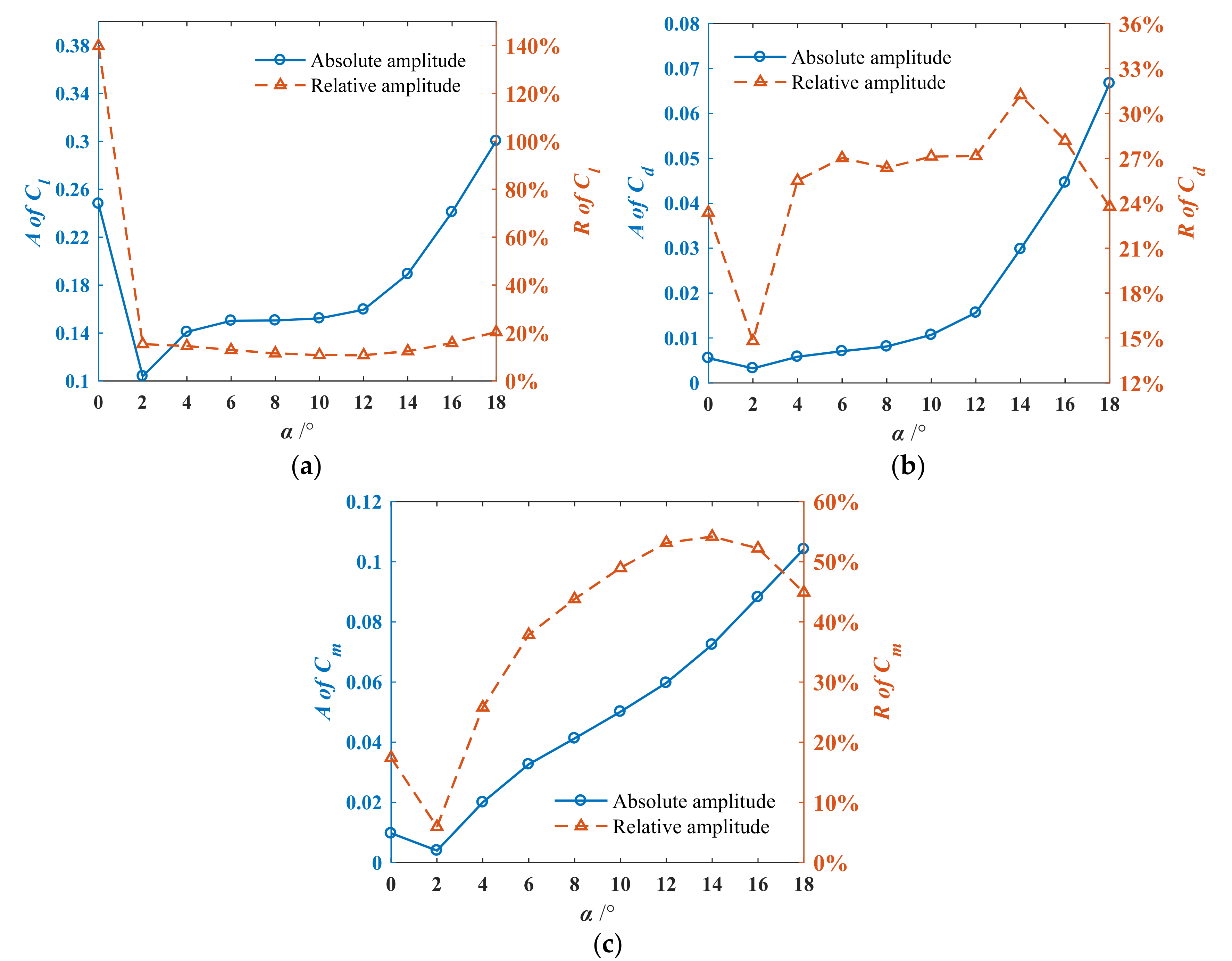
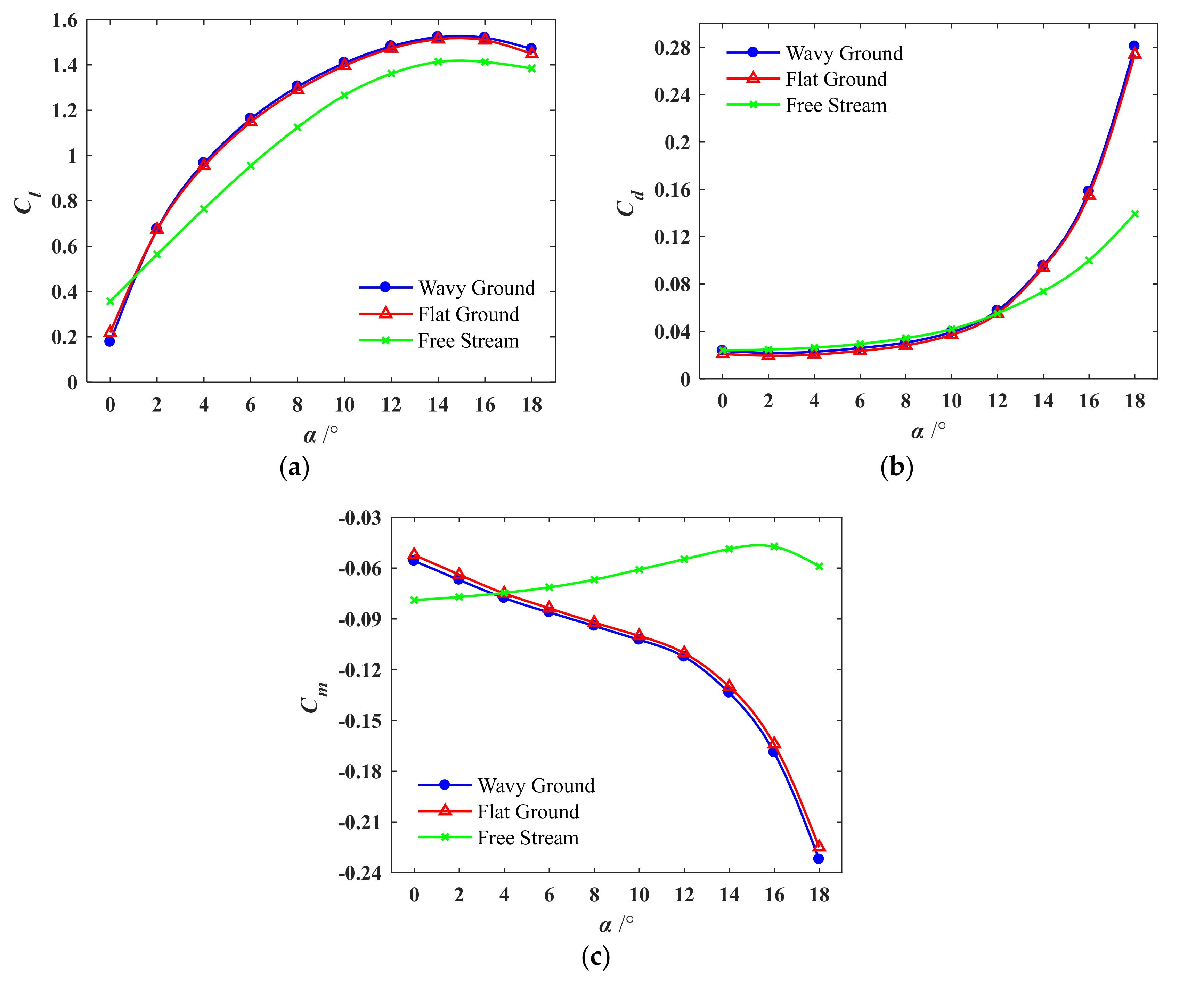
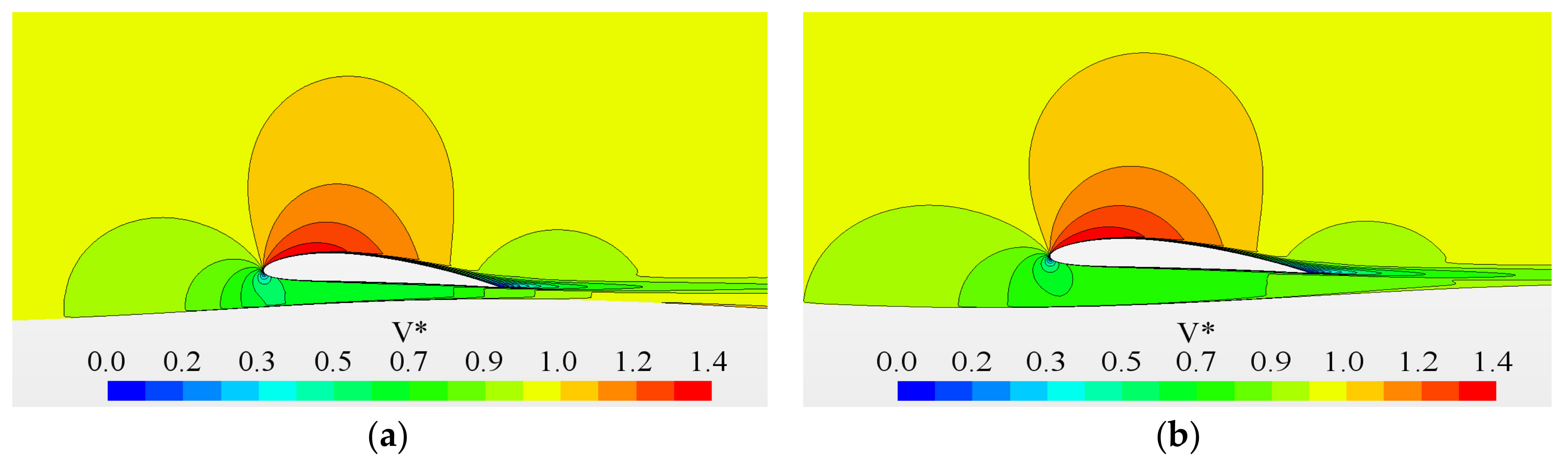
The structure of this paper is as follows. Firstly, the numerical calculation model is defined, and the numerical calculation method is verified. Subsequently, the numerical simulation of the airfoil moving over the wavy ground is conducted. The aerodynamic coefficients under a series of angles of attack are analyzed, including the fluctuation amplitude and time-averaged value. The time-averaged value is compared with that of free stream, flat ground, and wavy ground. Finally, the structure of the flow field is analyzed.
In this study, it is found that when the airfoil moves over wavy ground, the variation in aerodynamic coefficients at a small angle of attack is different from that of other angles of attack, and the fluctuation amplitude of aerodynamic coefficients is significantly greater than that of other angles of attack. The mechanism for the difference is interpreted through an analysis of the structure of the flow field. The range of angles of attack suitable for the flight of WIG craft is given. By comparing the time-averaged aerodynamics under flat-ground and wavy-ground conditions, it is found that the wavy ground only causes fluctuation in the aerodynamic coefficient, but does not change the time-averaged value. All this is of practical significance for the design and safe flight of WIG crafts.

2. Numerical Method and Validation

In this paper, the airfoil NACA 4412 is selected. The chord length of the airfoil is 0.5 m, the incoming velocity is 30 m/s, and the corresponding Reynolds number is 1.0 × 10⁶. The ride height h between the airfoil and the ground is described by the distance between the trailing edge point of the airfoil and the ground. The selection of the reference points at the trailing edge point refers to the relevant papers in this field [3,16,20,21,22], so that this study can be compared with the existing study.
In this study, the ride height is set to h = 0.1c, where c is the chord length. The range of angles of attack is 0~18°. The shape of the wavy ground is represented by a sine function, where the wave amplitude a is 0.05c and the wavelength λ is 5c. The selection of the wave parameters refers to the studies mentioned in the introduction, thus this study can be compared with other research. The surface equation of wavy ground is shown in Equation (1), where x0 is the initial phase.
y = a sin ( 2 π / λ · x x 0 ) .
The computational domain is shown in Figure 1. The sliding grid technology is adopted, and the whole calculation domain is divided into upper and lower parts. During the calculation, the upper domain remains static, the lower part of the domain moves to the right at a velocity equal to the incoming flow velocity, and the upper and lower domain exchange data through their contact surface. The inlet boundary and the upper boundary is 20c away from the airfoil, and the outlet boundary is 25c. The inlet boundary condition is set as the velocity inlet, the upper boundary and the outlet boundary as the pressure outlet, the contact surface of the upper and lower domains as the interface, and the wavy ground as the non-slip wall. In order to avoid calculation divergence at the initial time, a section of flat ground is located in front of the wavy ground. The lengths of the wavy ground and the flat ground are 75c and 35c, respectively. The grid of the computational domain is shown in Figure 2. The structural grid is employed, and the grid near the airfoil and the ground is refined. The numerical simulation is carried out by solving the RANS equations coupled with the turbulence model k-e. The second-order implicit scheme and second-order upwind scheme are employed for time discretization and spatial discretization, respectively. The time step Δt is 0.00015 s, considering the stability of unsteady calculation. Equation (2) is usually satisfied.
u · Δ t Δ x < 1 ,
where Δx is the minimum grid size and u is the incoming velocity. The convergence standard is the momentum residual and the periodicity of the aerodynamic coefficient. The residuals of the momentum, turbulent kinetic energy, and continuity are less than 1 × 10⁻⁶. At the same time, the lift coefficient and drag coefficient change periodically. If these two conditions are satisfied simultaneously, the convergence of the numerical calculation is judged to be reached.
The validation of the computational fluid dynamics (CFD) calculation is performed before numerical calculation. Many scholars have conducted a lot of studies on the NACA 4412 airfoil with numerical calculations or experiments. Ahmed [28] conducted an experiment to study the aerodynamic characteristics of the NACA 4412 airfoil with the ground effect. The study here also investigates the problem of the ground effect. Therefore, the experimental data in Ahmed’s paper are used for CFD validation. The angle of attack of the airfoil is taken as 4°, the ride height of the airfoil is h/c = 0.15, and the Reynolds number is 3.0 × 10⁵. These conditions are consistent with Ahmed’s experimental conditions [28]. The ground in the calculation domain is set as a moving wall with the velocity of airflow, and the other boundary conditions are the same as those mentioned above. Grid independence verification is carried out in order to ensure that the calculation results are independent of the grid. The number of grids increases or decreases according to the same principle. Three groups of grid numbers are set—namely, coarse grid, medium grid, and fine grid. The number of nodes in the horizontal and vertical directions is adjusted according to the consistent principle to increase or decrease the number of grids. The calculation results in Table 1 show that the calculation results are almost unchanged when the number of grids exceeds the medium grid. Hence, the medium grid is selected in this study. After convergence, the fluctuation amplitude of the lift coefficient and drag coefficient is less than 1 × 10⁻⁶, which is far less than the lift coefficient and drag coefficient themselves. This indicates that the unphysical oscillation caused by numerical dispersion can be ignored.
Figure 3 shows the pressure coefficient of the airfoil. The calculation results are in good agreement with the experimental results.
This study involves unsteady calculations, so the unsteady calculation results need to be verified. Some scholars have studied the unsteady calculation of CFD [29,30,31]. In this paper, the unsteady numerical simulation of an NACA0015 airfoil oscillating in the pitching direction is carried out and compared with the experiment results [32]. The calculated parameters are consistent with those in the experiment. The incoming Mach number is 0.29, the Reynolds number is 1.95 × 10⁶, the airfoil angle of attack is 4°, the oscillation amplitude is 4.2°, and the oscillation frequency is 10 Hz. The calculation results are shown in Figure 4, and the airfoil lift coefficient is in good agreement with the experimental results.
There are numerical calculations of the airfoil at high angles of attack in this study. The airfoil will undergo flow separation at high angles of attack. Therefore, it is necessary to verify the accuracy of the numerical results at high angles of attack. The NASA experimental data [33] are selected for numerical verification, and the results are also compared with the numerical results of Qu [10]. The airfoil is NACA 4412, the Reynolds number is 6 × 10⁶, and the free stream velocity is 88 m/s. The calculation results of the shear stress transport (SST) for two turbulence models k-e and k-ω are shown in Figure 5.
Since a negative angle of attack is not involved in this study, the calculation of a negative angle of attack is not considered. It can be seen from Figure 5 that the results of the two turbulence models are both in good agreement with the experimental results, as the angle of attack is less than 12°. As the angle of attack is greater than 12°, the calculation results of the k-e turbulence model are closer to the experimental results than the k-ω SST and also better than Qu, which is the reason for the selection of the k-e turbulence model. However, after the stall angle of attack of 15°, the calculated results do not agree well with the experimental results. At a high angle of attack, especially for angles greater than the stall angle of attack, the airfoil is faced with flow separation, and the separation region is often accompanied by a shedding vortex. Therefore, the flow field around the airfoil is more complex than that at a low angle of attack. Flow separation occurs when the airfoil angle of attack is essentially a complicated turbulent flow. The turbulence model in RANS is an empirical model that is established on simplified assumptions. Hence, the RANS cannot fully simulate the details of the real flow [34]. It is fair to say that the simulation of separated flow at a high angle of attack is still a challenge for CFD.

3. Results and Discussion

3.1. Aerodynamic Behavior

The trailing edge point of the airfoil, which is taken as the reference point, is directly above the peak of wavy ground at the beginning. T is the time that is taken for the airfoil to move from one peak of wavy ground to the next. The variable t* = t/T is defined to describe the relative position between the airfoil and the wavy ground. The trailing edge point of the airfoil is directly above the peak at t* = 0 and t* = 1, hence the two moments are equivalent. Since the aerodynamics of the airfoil change periodically, one period is taken for analysis. The aerodynamic coefficients are the lift coefficient Cl, the drag coefficient Cd, and the moment coefficient Cm. The point for calculating the moment is 1/4 chord length from the leading edge of the airfoil.
The aerodynamic coefficients of different angles of attack in a period are shown in Figure 6. It can be seen that the trend of the aerodynamic coefficient at a 0° angle of attack is different from that at other angles of attack. The aerodynamic coefficients at other angles of attack have the same trend, similar to the sine curves. The lift coefficient increases with the increase in the angle of attack, but the rate of increase is decreasing, which is indicated by the smaller and smaller curve intervals in Figure 6. The lift coefficient curve no longer moves up from a 14° angle of attack, and the fluctuation amplitude increases obviously. The moment coefficient curve moves down with the increase in the angle of attack, and the fluctuation amplitude increases. The interval between the moment curves increases with the increase in the angle of attack, indicating that the rate of change is increasing. The time-averaged value and fluctuation amplitude of the drag coefficient change little in the range of 0~8° angles of attack. When the angle of attack exceeds 10°, the drag coefficient increases rapidly, and the fluctuation amplitude also increases with the angle of attack.
The fluctuation amplitude of the aerodynamic coefficient is defined as A and R. A is the absolute amplitude of the aerodynamic coefficient, and R is the relative amplitude of the aerodynamic coefficient. Their definitions are shown in Equations (3) and (4), respectively. Cmax and Cmin are the maximum and minimum aerodynamic coefficients in a period, respectively, and Ctime-averaged is the time-averaged value of the aerodynamic coefficient in a period. The time-averaged value is the integral of the coefficient over time in one period divided by T, as shown in Equation (5).
A = C max C min ,
R = ( C max C min ) / C t i m e a v e r a g e d ,
C t i m e a v e r a g e d = T C d t / T .
Figure 7 presents the fluctuation amplitude of an aerodynamic coefficient varying with the angle of attack. The left longitudinal axis is the absolute amplitude, and the right longitudinal axis is the relative amplitude. At a 0° of attack, the absolute amplitude of the lift coefficient is large, while the time-averaged lift coefficient is small, resulting in the maximum relative amplitudes among all angles of attack. The absolute amplitude of the lift coefficient increases with the increase in angle of attack from 2°, varies slightly within the range of 6° to 10°, then increases rapidly from 12°. The relative amplitude decreases from 2° to 10° and increases from 10° to 18°, reaching the minimum of 10.8% at 10°. The absolute amplitude of the drag coefficient is smallest when the angle of attack is 2°and gradually increases with angle of attack from 2°. In the range of 2° to 10°, the increase rate of the absolute amplitude is relatively slow, while the increase rate is relatively fast in the range of 10° to 18°. The relative amplitude of the drag coefficient is smallest at 2°, changes little between 4° and 12°, and increases rapidly at 14°. However, the time-averaged value increases more rapidly, causing the relative fluctuation to decrease from 14°. The absolute amplitude of the moment coefficient increases near-linearly with the angle of attack from 2°. The relative amplitude increases with the increase in the angle of attack from 2°, reaches its maximum at 14°, and then decreases gradually.
Therefore, the medium angle of attack (2~10°) should be selected as the design cruise angle of attack for the WIG craft. Within this range of angle of attack, the fluctuation amplitude of lift coefficient and moment coefficient is relatively small, and the fluctuation amplitude of drag coefficient changes little, thus avoiding the large bump of the WIG craft when flying near the wavy ground or water wave and facilitating the control of the craft. The 0° angle of attack should be avoided as the design cruise angle of attack at which the fluctuation of lift coefficient exceeds 100%, which can cause severe bumps during takeoff/landing and even endanger flight safety. The maneuverability of the WIG craft is deficient in the situation of a high angle of attack. If the WIG craft encounters a high angle of attack when it is flying near the wavy ground or water wave, the fluctuation in the aerodynamic coefficients will deteriorate the maneuverability of the aircraft.
Figure 8 shows the time-averaged aerodynamic coefficient varying with the angle of attack in a period. The aerodynamic coefficients in the situation of free stream and flat ground are also given. Other conditions, except the ground boundary conditions, are the same for wavy ground, flat ground, and free stream. It can be seen from the figure that the time-averaged aerodynamic coefficients in the case of wavy ground are close to those in the case of flat ground, whether at small or high angles of attack. It can be concluded that, among all angles of attack, the wavy ground only causes a fluctuation in the aerodynamic coefficient compared with flat ground. However, it should be noted that the fluctuation amplitude of the aerodynamic coefficients varies at different angles of attack, there are no clearly predictable laws, and even the trend of aerodynamics is changed at a 0° angle of attack. The fluctuation in aerodynamics is the peculiarity of the aerodynamic characteristics of an airfoil moving over a wavy ground. There is an apparent difference between aerodynamic coefficients in the case of ground effect and those in the case of free stream. In the case of free stream, the lift coefficient curve has an obvious linear section when the angle of attack is less than 8°, while there is no linear section of lift coefficient in the case of ground effect. Within the range of a 0~4° angle of attack, the change rate of the lift coefficient with the angle of attack is large, and then the change rate becomes smaller from 4°. Within the range of a 0~12° angle of attack, the drag coefficient in the case of ground effect is almost the same as that in the case of free stream. As the angle of attack is higher than 12°, the drag coefficient in the case of ground effect increases sharply, while the drag coefficient in the case of free stream increases slowly. Moment coefficient has a significant difference between the ground effect condition and the free stream condition. The moment coefficient in the case of free stream increases with the increase in the angle of attack and decreases near the stall angle of attack. In the case of ground effect, the moment coefficient decreases with the increase in the angle of attack, which enhances the pitch maneuverability of the WIG craft when encountering high angles of attack.

3.2. Flow Field Analysis

The aerodynamic coefficient varying with time at a 0° angle of attack is different from that at other angles of attack, which have the same trend in a period. The lift coefficient at a 4° angle of attack is taken as an example. The lift coefficient reaches the minimum at t* = 0.25, and then reaches the maximum at t* = 0.75. At a 0° angle of attack, the lift coefficient reaches the maximum at t* = 0.5, and then reaches the minimum at t* = 0.84. Figure 9 and Figure 10 show the velocity contours at different moments of 4° and 0° angles of attack, respectively. Figure 11 shows the pressure coefficient distribution on the surface of the airfoil at corresponding moments. The pink vertical dotted line in the figure is the relative position of the moment reference point on the airfoil. The pressure coefficient is defined as Equation (4), where p is the local pressure, p and V are the pressure and velocity of the incoming flow far ahead, and ρ is the air density.
C p = p p 1 / 2 ρ V 2 .
It can be seen from Figure 9 that the flow channel between the airfoil and the wavy ground at a 4° angle of attack expands gradually during the period of t* = 0 to t* = 0.25, which results in the weakening of the blocking effect on the airflow. Therefore, the velocity of air in the flow channel increases, the pressure on the lower surface of the airfoil decreases, and the lift coefficient on the lower surface of the airfoil decreases. It can be seen from the pressure distribution in Figure 11 that the pressure coefficient of the lower surface of the airfoil decreases, while the pressure coefficient of the upper surface changes little in the whole period. The reason for the pressure coefficient of the upper surface is that the velocity distribution around the upper surface has little change. Figure 11 also presents that the pressure reduction in the lower surface is more distributed behind the moment reference point, which leads to an increase in the moment coefficient. At t* = 0.25, the leading edge of the airfoil reaches the trough of wavy ground, which means that the distance between the leading edge of the airfoil and the wavy ground reaches a maximum. At t* = 0.75, the leading edge of the airfoil reaches the peak, and the distance between the airfoil and the ground reaches the minimum. Consequently, the flow channel under the airfoil contracts gradually in the period of t* = 0.25~0.75, which results in a decrease in the stream velocity, an increase in the pressure in the flow channel, and an increase in the lift coefficient of the airfoil. The increase in pressure on the lower surface is more distributed behind the moment reference point, thus the moment coefficient of the airfoil decreases gradually. From t* = 0.75 to t* = 1.0, the distance between the leading edge of the airfoil and the ground increases gradually, and the flow channel expands during this period. The result is that the stream velocity increases and the pressure decreases, thus the lift coefficient decreases with the increase in the moment coefficient. The trend of aerodynamic coefficients at other angles of attack except 0° is consistent with that at a 4° angle of attack, and correspondingly their flow field structures are consistent with the above analysis. It can be concluded that the change in aerodynamic coefficients is caused by the expansion or contraction of the flow channel between the lower surface of the airfoil and the wavy ground.
The following is an analysis of the phenomenon where the trend of aerodynamic coefficients at a 0° angle of attack in a period is different from that at other angles of attack. At t* = 0, the stream velocity under the lower surface is higher than that at the 4° angle of attack. As can be seen from the comparison of Figure 9 and Figure 10, the position of the stagnation point of the leading edge at a 0° angle of attack is higher than that at the 4° angle of attack. At the same time, the leading edge of the airfoil at the angle of attack of 0° is closer to the ground. These two factors lead to the larger shrinkage of the cross section near the inlet of the flow channel, which leads to the more significant acceleration effect of the airflow in the flow channel. In Figure 11, it can be seen that there is a negative pressure peak on the lower surface, which is caused by the acceleration of the airflow. The negative pressure peak is even smaller than the pressure peak on the upper surface. In the period of t t* = 0~0.25, the distance between the leading edge of the airfoil and the ground increases, the shrinkage of the flow channel decreases, and the acceleration effect of the airflow in the flow channel weakens. The airflow deceleration effect caused by the shrinkage of the flow channel exceeds the airflow acceleration effect caused by the expansion of the flow channel. Therefore, the airflow decelerates, and the pressure on the lower surface increases, resulting in an increase in the lift coefficient. The deceleration effect is more significant near the leading edge of the airfoil, and the pressure increment on the lower surface is concentrated near the leading edge, which leads to an increase in the moment coefficient. In the period of t* = 0.25~0.5, the distance between the leading edge of the airfoil and the ground decreases, the blocking effect on the airflow increases, and the shrinkage of the flow channel near the leading edge does not change significantly. Therefore, the airflow velocity in the flow channel decreases, the pressure increases, and the lift coefficient increases. In the period of t* = 0.5~0.84, the distance between the leading edge of the airfoil and the ground decreases, and the shrinkage of the flow channel near the leading edge becomes significant again. The significant shrinkage of the flow channel results in an increase in the stream velocity, a decrease in the pressure near the leading edge of the airfoil, and a decrease in the lift coefficient. The decrease in the pressure peak on the lower surface can be seen in Figure 11. Although the pressure peak in front of the moment reference point is significantly reduced, the backward shift of the pressure peak causes a weakening of the effect of changing the moment. At the same time, there is also a significant pressure reduction behind the moment reference point, and the arm of force based on the reference point is large. Therefore, the contribution of the pressure reduction behind the reference point to the increase in the moment coefficient exceeds the contribution of the pressure peak reduction to the decrease in the moment coefficient, and the moment coefficient increases. In the period of t* = 0.84~1.0, the distance between the leading edge of the airfoil and the ground begins to increase, the shrinkage of the flow channel decreases, the acceleration effect weakens, the stream velocity decreases, and the pressure increases, resulting in an increase in the lift coefficient. The pressure reduction in front of the moment reference point is significant. However, the arm of force is small, the effect on the moment is less than that on the pressure increment behind the moment reference point, which leads to a decrease in the moment coefficient.
It can be concluded that the flow mechanism of the airfoil moving over wavy ground at a small ride height at a 0° angle of attack is different from that at other angles of attack. There is not only the acceleration and deceleration of the airflow caused by the expansion and contraction of the flow channel, but also the change in the airflow velocity caused by the change in the shrinkage at the inlet of the flow channel. When the distance between the leading edge of the airfoil and the ground is small, the change in velocity caused by the change in the shrinkage at the inlet of the flow channel will exceed that caused by the expansion or contraction effect of the flow channel. Figure 11 presents a significant difference in the pressure distribution of the airfoil at a 0° angle of attack and 4° angle of attack. Therefore, the trend of aerodynamic coefficient at the 0° angle of attack is different from that at other angles of attack.
Figure 12 and Figure 13 demonstrate the lift coefficient and moment coefficient in a period of different ride heights at 0° and 4° angles of attack, respectively. Since the time-averaged value and the fluctuation amplitude of the drag coefficient change little in the range of 0~8° angle of attack, the drag coefficient will not be discussed.
Figure 13 presents that the aerodynamic coefficients of different ride heights have the same trend in a period at a 4° angle of attack, and the difference is that the position of aerodynamic coefficient curve has moved. The reason is that the ground effect is weaker and weaker with the increase in the ride height, the aerodynamic coefficients are gradually similar to those in the case of free stream, and the fluctuation amplitude is reduced. As can be seen from Figure 12, at a 0° angle of attack, the trend of the aerodynamic coefficient at the ride height of h/c = 0.1 is different from that at other altitudes. With the increase in ride height, the change in shrinkage near the inlet of the flow channel decreases and no longer plays a leading role in the acceleration and deceleration effect of the airflow.
Figure 14 presents the pressure coefficient distribution of the airfoil at different moments in a period in the situation of h/c = 0.2 and α = 0°. The pressure coefficients near the leading edge of the lower surface have no sharp changes compared with those in Figure 12. The upward movement of the leading-edge stagnation point at an angle of attack of 0° causes an acceleration of the airflow near the leading edge. Thus, a pressure peak near the leading edge of the lower surface forms which is similar to the suction peak near the leading edge of the upper surface at a 4° angle of attack. Figure 12 and Figure 13 also show that when the ride height exceeds h/c = 0.6 at angles of attack of 0° and 4°, the change in the time-averaged aerodynamic coefficient is very small, and the fluctuation amplitude is also very small. As the ride height reaches 1, the fluctuation amplitude tends to be zero, and the aerodynamic coefficient is very close to that in the case of free stream. This means that the ground effect is no longer significant when the ride height is greater than 1.

4. Conclusions

In this paper, the aerodynamics of a NACA 4412 airfoil in a wide range of 0~18° angles of attack when moving over wavy ground at a small ride height are studied. The wavy ground will cause the aerodynamic coefficient of the airfoil to fluctuate periodically, and the trend of the aerodynamic coefficient at a 0° angle of attack is different from that of other angles of attack. The relative fluctuation amplitude of the lift coefficient at a 0° angle of attack exceeds 100%. WIG craft flying near the ground at this angle of attack will generate big bumps. When the angle of attack is greater than 10°, the fluctuations in the lift coefficient, moment coefficient, and drag coefficient are large, which will cause a deterioration in the WIG craft maneuverability. Therefore, WIG craft should cruise at a moderate angle of attack to avoid flying at small and high angles of attack.
The time-averaged aerodynamics in the case of wavy ground is almost the same as those in the case of flat ground. The wavy ground mainly causes a fluctuation in the aerodynamics. Therefore, the trend and fluctuation amplitude of aerodynamics should be paid more attention when airfoils and WIG crafts move over wavy ground at a small ride height. The trend of aerodynamic coefficients at a 0° angle of attack and at other angles of attack are different because of its unique flow field structure. The trend of aerodynamic coefficients at other angles of attack is mainly caused by the contraction and expansion of the flow channel under the airfoil, while at 0 degrees of attack there is also the acceleration and deceleration effect of the airflow, caused by the change in the shrinkage of the flow channel.
This paper studies the ground effect in the case of wavy ground and analyzes the flow field around the airfoil. All this is of practical significance to the design and safe flight of WIG crafts.

Author Contributions

D.M. and H.H. proposed the original idea. H.H. performed the numerical simulations and wrote the paper; D.M. reviewed the paper and helped to revise it. All authors have read and agreed to the published version of the manuscript.

Funding

This research received no external funding.

Conflicts of Interest

The authors declare no conflict of interest.

References

  1. Rozhdestvensky, K.V. Wing-in-ground effect vehicles. Prog. Aerosp. Sci. 2006, 42, 211–283. [Google Scholar] [CrossRef]
  2. Lange, R.H.; Moore, J.W. Large Wing-in-Ground Effect Transport Aircraft. J. Aircr. 1980, 17, 260–266. [Google Scholar] [CrossRef]
  3. Hsiun, C.-M.; Chen, C.-K. Aerodynamic characteristics of a two-dimensional airfoil with ground effect. J. Aircr. 1996, 33, 386–392. [Google Scholar] [CrossRef]
  4. Jamei, S.; Maimun, A.; Mansor, S.; Sidik, N.A.C.; Priyanto, A. Numerical Investigation on Aerodynamic Characteristics of a Compound Wing-in-Ground Effect. J. Aircr. 2012, 49, 1297–1305. [Google Scholar] [CrossRef]
  5. Jung, J.H.; Yoon, H.S.; Chun, H.H.; Hung, P.A.; El-Samni, O.A. Mean flow characteristics of two-dimensional wings in ground effect. Int. J. Nav. Arch. Ocean Eng. 2012, 4, 151–161. [Google Scholar] [CrossRef] [Green Version]
  6. Jung, J.H.; Kim, M.J.; Yoon, H.S.; Hung, P.A.; Chun, H.H.; Park, D.W. Endplate effect on aerodynamic characteristics of three-dimensional wings in close free surface proximity. Int. J. Nav. Arch. Ocean Eng. 2012, 4, 477–487. [Google Scholar] [CrossRef] [Green Version]
  7. Qu, Q.; Jia, X.; Wang, W.; Liu, P.; Agarwal, R.K. Numerical Simulation of the Flowfield of an Airfoil in Dynamic Ground Effect. J. Aircr. 2014, 51, 1659–1662. [Google Scholar] [CrossRef]
  8. Ockfen, A.E.; Matveev, K.I. Aerodynamic characteristics of NACA 4412 airfoil section with flap in extreme ground effect. Int. J. Nav. Arch. Ocean Eng. 2009, 1, 1–12. [Google Scholar] [CrossRef] [Green Version]
  9. Yang, Z.; Wei, Y. Complex Flow for Wing-in-ground Effect Craft with Power Augmented Ram Engine in Cruise. Chin. J. Aeronaut. 2010, 23, 1–8. [Google Scholar] [CrossRef] [Green Version]
  10. Qu, Q.; Wang, W.; Liu, P.; Agarwal, R.K. Airfoil Aerodynamics in Ground Effect for Wide Range of Angles of Attack. AIAA J. 2015, 53, 1048–1061. [Google Scholar] [CrossRef]
  11. Qu, Q.; Jia, X.; Wang, W.; Liu, P.; Agarwal, R. Numerical study of the aerodynamics of a NACA 4412 airfoil in dynamic ground effect. Aerosp. Sci. Technol. 2014, 38, 56–63. [Google Scholar] [CrossRef]
  12. Lilienthal, T.; Matsuda, A.; Thomas, G. Dynamic stability in following seas: Predictive and experimental approaches. J. Mar. Sci. Technol. 2007, 12, 111–118. [Google Scholar] [CrossRef]
  13. Zong, Z.; Liang, H.; Zhou, L. Lifting line theory for wing-in-ground effect in proximity to a free surface. J. Eng. Math. 2011, 74, 143–158. [Google Scholar] [CrossRef]
  14. Liang, H.; Zhou, L.; Zong, Z.; Sun, L. An analytical investigation of two-dimensional and three-dimensional biplanes operating in the vicinity of a free surface. J. Mar. Sci. Technol. 2012, 18, 12–31. [Google Scholar] [CrossRef]
  15. Bal, S. Free surface effects on 2-D airfoils and 3-D wings moving over water. Ocean Syst. Eng. 2016, 6, 245–264. [Google Scholar] [CrossRef]
  16. Im, Y.-H.; Chang, K.-S. Unsteady Aerodynamics of a Wing-in-Ground-Effect Airfoil Flying over a Wavy Wall. J. Aircr. 2000, 37, 690–696. [Google Scholar] [CrossRef]
  17. Qu, Q.; Lu, Z.; Liu, P.; Agarwal, R.K. Numerical Study of Aerodynamics of a Wing-in-Ground-Effect Craft. J. Aircr. 2014, 51, 913–924. [Google Scholar] [CrossRef]
  18. Gao, B.; Qu, Q.; Agarwal, R.K. Aerodynamics of a Transonic Airfoil above Wavy Ground. In Proceedings of the 2018 AIAA Aerospace Sciences Meeting, Kissimmee, FL, USA, 8–12 January 2018. [Google Scholar] [CrossRef]
  19. Liang, H.; Wang, X.; Zou, L.; Zong, Z. Numerical study of two-dimensional heaving airfoils in ground effect. J. Fluids Struct. 2014, 48, 188–202. [Google Scholar] [CrossRef]
  20. Lee, T.; Tremblay-Dionne, V. Experimental Investigation of the Aerodynamics and Flowfield of a NACA 0015 Airfoil over a Wavy Ground. J. Fluids Eng. 2018, 140, 071202. [Google Scholar] [CrossRef]
  21. Tremblay-Dionne, V.; Lee, T. Effect of Trailing-Edge Flap Deflection on a Symmetric Airfoil Over a Wavy Ground. J. Fluids Eng. 2018, 141, 064501. [Google Scholar] [CrossRef]
  22. Zhi, H.; Xiao, T.; Chen, J.; Wu, B.; Tong, M.; Zhu, Z. Numerical Analysis of Aerodynamics of a NACA4412 Airfoil above Wavy Water Surface. In Proceedings of the AIAA Aviation 2019 Forum, Dallas, TX, USA, 17–21 June 2019; Volume 3694. [Google Scholar] [CrossRef]
  23. Yousefi, K.; Veron, F.; Buckley, M. Momentum flux measurements in the airflow over wind-generated surface waves. J. Fluid Mech. 2020, 895, 895. [Google Scholar] [CrossRef]
  24. Yousefi, K.; Veron, F. Boundary layer formulations in orthogonal curvilinear coordinates for flow over wind-generated surface waves. J. Fluid Mech. 2020, 888, 888. [Google Scholar] [CrossRef]
  25. Buckley, M.; Veron, F. Structure of the Airflow above Surface Waves. J. Phys. Oceanogr. 2016, 46, 1377–1397. [Google Scholar] [CrossRef] [Green Version]
  26. Sullivan, P.P.; McWilliams, J.C. Dynamics of Winds and Currents Coupled to Surface Waves. Annu. Rev. Fluid Mech. 2010, 42, 19–42. [Google Scholar] [CrossRef] [Green Version]
  27. Husain, N.T.; Hara, T.; Buckley, M.P.; Yousefi, K.; Veron, F.; Sullivan, P.P. Boundary Layer Turbulence over Surface Waves in a Strongly Forced Condition: LES and Observation. J. Phys. Oceanogr. 2019, 49, 1997–2015. [Google Scholar] [CrossRef]
  28. Ahmed, M.R.; Takasaki, T.; Kohama, Y. Aerodynamics of a NACA4412 Airfoil in Ground Effect. AIAA J. 2007, 45, 37–47. [Google Scholar] [CrossRef]
  29. Gill, P.; Visone, M.; Lerro, A.; Vivo, F.; Scognamiglio, G. A New Approach for the Estimation of Longitudinal Damping Derivatives: CFD Validation on NACA 0012. In Proceedings of the 6th International Conference on THEORETICAL and APPLIED MECHANICS: Makassar, Indonesia. WSEAS Trans. Fluid Mech. 2015, 10, 137–145. [Google Scholar]
  30. Rival, D.; Tropea, C. Characteristics of Pitching and Plunging Airfoils under Dynamic-Stall Conditions. J. Aircr. 2010, 47, 80–86. [Google Scholar] [CrossRef] [Green Version]
  31. Bergmann, A.; Huebner, A.; Loeser, T. Experimental and numerical research on the aerodynamics of unsteady moving aircraft. Prog. Aerosp. Sci. 2008, 44, 121–137. [Google Scholar] [CrossRef]
  32. Piziali, R.A. 2-D and 3-D Oscillating Wing Aerodynamics for a Range of Angles of Attack Including Stall; Ames Research Center: Moffett Field, CA, USA, 1 September 1994. [Google Scholar]
  33. Abbott, I.H.; Von Doenhoff, A.E.; Stivers, L.J. Summary of Airfoil Data. 1 January 1945. Available online: http://ntrs.nasa.gov/search.jspR=19930090976 (accessed on 25 September 2020).
  34. Cummings, R.M.; Forsythe, J.R.; Morton, S.A.; Squires, K.D. Computational challenges in high angle of attack flow prediction. Prog. Aerosp. Sci. 2003, 39, 369–384. [Google Scholar] [CrossRef] [Green Version]
Figure 1. Computational domain for moving over wavy ground.
Applsci 10 06773 g001
Figure 2. Grid for computational domain.
Applsci 10 06773 g002
Figure 3. Pressure coefficient distribution with the ground effect.
Applsci 10 06773 g003
Figure 4. Lift coefficient of the NACA0015 airfoil with pitching oscillation.
Applsci 10 06773 g004
Figure 5. Lift coefficient curve for NACA4412.
Applsci 10 06773 g005
Figure 6. The change in aerodynamics in a period: (a) lift coefficient, (b) moment coefficient, (c) drag coefficient.
Applsci 10 06773 g006
Figure 7. The amplitude of aerodynamic coefficient: (a) lift coefficient, (b) drag coefficient, (c) moment coefficient.
Applsci 10 06773 g007
Figure 8. Variation in the time-averaged aerodynamics with the angle of attack: (a) lift coefficient, (b) drag coefficient, (c) moment coefficient.
Applsci 10 06773 g008
Figure 9. Velocity contours of different moments at α = 4°: (a) t* = 0.0, (b) t* = 0.25, (c) t* = 0.5, (d) t* = 0.75.
Applsci 10 06773 g009aApplsci 10 06773 g009b
Figure 10. Velocity contours of different moments at α = 0°: (a) t* = 0.0, (b) t* = 0.25, (c) t* = 0.5, (d) t* = 0.84.
Applsci 10 06773 g010aApplsci 10 06773 g010b
Figure 11. Pressure coefficient distributions on the airfoil of different moments (a) α = 0°, (b) α = 4°.
Applsci 10 06773 g011
Figure 12. The change in the aerodynamics of different ride heights at α = 0°: (a) lift coefficient, (b) moment coefficient.
Applsci 10 06773 g012
Figure 13. The change in the aerodynamics of different ride heights at α = 4°: (a) lift coefficient, (b) moment coefficient.
Applsci 10 06773 g013
Figure 14. Pressure coefficient distribution of h/c = 0.2 at α = 0°.
Applsci 10 06773 g014
Table 1. Grid independence study.
MeshCell NumbersY+ClCd
coarse127,18820.868900.01162
medium209,12710.868960.01143
fine311,1210.50.868920.01146

