Abstract
Topological optimization can realize the optimization of the mass distribution in the whole objective domain. Compared with morphology and size optimization, it has a higher degree of freedom. In this work, the three-dimensional topological optimization based on piezoelectric materials was discussed. Using the Optimality Criteria, topology optimization was applied to the cantilever piezoelectric transducer. The structure optimization was realized with the voltage and stiffness as the multi-objective function. The corresponding codes are given to show the process of optimization. With 70% of the origin volume, the bi-objective optimization increases the global stiffness by 50.9% and the voltage by 30%. As the iteration process shows, the results of bi-objective optimization prove the value of additive mass at the bottom of the cantilever. This lays the foundation for future piezoelectric transducer structural optimization. Using only stiffness as the objective, the final objective increases inconspicuously. Bi-objective optimization shows its superiority. There are quite a few papers that research the combination of stiffness and voltage, and research which studies three-dimensionality is a point of innovation. Furthermore, this is also the first time a piezoelectric topology code has been shared.
1. Introduction
Fossil fuel energy reserves are declining and will fade out of human history in the near future. Consequently, new sustainable energy sources are becoming more and more popular for researchers. State-of-the-art, small-scale electronic devices have promoted the need for portable, small, efficient, self-powered energy generators. Such small-scale electronic devices are hard to charge considering their size and commonly far-away location. Therefore, the self-powering property is an intriguing solution to this [1,2]. Piezoelectric material can exactly fulfill these requirements. By capturing the pressure or movement of the natural world, a piezoelectric harvester could generate electric power. Moreover, it could capture outside disturbance, which could also serve as a sensor. Therefore, the design of the piezoelectric harvester is the key question explored here.
The designs of piezoelectric actuators and energy harvesters are complicated [3,4,5,6]. In recent years, topological optimization and other systematic design methods have been successfully applied to solve the optimization problem, and the optimal design has been obtained. By combining the homogenization method with the topology optimization method, the unit cell topology could be optimized. Using the Sequential Linear Programming (SLP) method, the material topology is realized [7,8]. The design variables describe the allocation of piezoelectric material and polarization degrees at each finite element unit, and this can be applied to the design of sensors, actuators, and energy harvesters [9,10]. The geometric design freedom and multi-material parallelism of 3D printing make it possible to manufacture topology-optimized flexible mechanisms. Abbas et al. researched a 2D piezoelectric topology problem, and discovered the best possible layout to overcome the charge cancellation problem [11]. Chamoin et al. researched the topology optimization problem surrounding hydrophones. Using the level set method, the hydrostatic charge efficiency is enhanced [12]. Creaco et al. propose the bi-objective optimization for the installation of pumps operating as turbines (PATs) in systems of transmission mains [13].
Cory et al. [14] used topology optimization to design piezoelectric energy harvesting systems based on multilayer plates and shells. They employed the finite element method in order to build a coupled electromechanics model of the piezoelectric harvesting structure and a lumped parameter. This was done to develop overarching design principles for piezoelectric energy harvesting devices. Martin et al. [15] studied the topology optimization of the design of piezoelectric plate and shell actuators. The aim of this was to achieve maximum output displacement in a given direction at a given point of the structure, whilst simultaneously minimizing the structural compliance. Carbonari et al. [16] designed piezoelectric actuators based on the flexible structure actuated by piezoceramics. A simultaneous search was conducted in order to discover the position of the piezoceramic in the design domain and the optimal rotation angles of piezoceramic material axes that maximize output displacements or output forces. Ha et al. [17] et al. developed the design sensitivity analysis and topology design optimization methods for piezoelectric resonators, and computed the necessary design gradients for eigenvalue problems. Kiyono et al. [18] studied the laminated piezo composite shell structures using topology optimization, with the polarization distributions of the piezoelectric material and the fiber angle of the composite orthotropic layers as the objective. Sivapuram et al. [19] introduced a new method to optimize structure and material simultaneously, by linearizing and formulating in order to solve the macro and microscale design problems, and to gain an overall optimum solution. Ivan et al. proved that a topology problem could be reformed into an image segmentation task, and that this could then be solved using a deep neural network [20]. Zhu et al. proposed a review that shows the wide usage of the topology method utilized on aircraft designs. The problems of stiffness ribs design, multi-component design, and multi-fasteners design could be solved using the topology method [21]. Sigmund et al. presented a 2D topology code using the Optimality Criteria (OC) method [22]. Liu et al. extended the topology research into the 3D situation and provided relevant codes [23].
At present, piezoelectric topology focuses on improving the electromechanical conversion coefficient and reducing material flexibility, however there is little multi-objective research exploring binding power output and natural frequency. This is because of the low manufacturability after topology design, and the emergence of 3D printing solves this problem. In recent years, the study of topology optimization has been developed rapidly.
In this work, the three-dimensional topological optimization based on piezoelectric materials has been discussed. Using the Optimality Criteria, topology optimization is applied to the cantilever piezoelectric transducer. The structure optimization was realized with the voltage and stiffness as the objective function. The corresponding codes are given to show the process of optimization. This bi-objective optimization shows an obvious increase in both stiffness and voltage output. As the iteration process shows, the results of bi-objective optimization prove the value of additive mass at the bottom of the cantilever. This lays the foundation for future piezoelectric transducer structural optimization. Using only stiffness as the objective, the objective increases inconspicuously. Bi-objective optimization shows its superiority. As far as the author knows, relevant research that focuses on stiffness and voltage is limited, and even fewer papers extend it to the 3D situation. Existing papers [24,25] have conducted research based on the 2D situation for simplicity, and some of them used a truss structure. Their research results focus on amplifying displacement and enhancing electromechanical conversion efficiency. Therefore, this research, which focuses on enhancing the voltage and stiffness of the piezoelectric energy harvester based on the 3D situation, is innovative. Additionally, this is also the first time a piezoelectric topology code has been shared.
2. Topology Optimization Problem
Topology optimization is one aspect among various optimization problems. Its core theory is to adjust and optimize the mass distribution variable, ‘x’, which is the percentage of the mass distribution for each unit, leading to the optimal mass distribution of the overall structure and the minimum of the objective function value. Hence, in this work, topology optimization can be written as , and the equation is shown as Equation (1)
The objective function consists of SE (strain energy) and MSE (mutual strain energy). SE refers to compliance, and the overall stiffness of the structure can be enhanced by minimizing SE. MSE refers to the compliance of a certain point, and the voltage output can be enlarged by maximizing MSE. It is expected that the piezoelectric transducer possesses a larger overall stiffness and a larger displacement of the top point, so as to achieve a larger electrical output. The step to solve MSE involves replacing the originally applied force with the unit force at the required point [26].
Where the constraints of equality and inequality are presented as Equations (4)–(6).
, , and are global displacement, load, potential, and the global charge matrix, respectively. Correspondingly, , and are overall stiffness matrix, piezoelectric matrix, and dielectric matrix, respectively. Meanwhile, , and are that of a single element, respectively. is the number of all elements. If we assume that , and are the cuboid dimensions in three directions, then it is obvious that . ‘x’ is the variable in the topology optimization process, whose numerical value is between 0 and 1. If ‘x’ of a single element is 0, we consider that the element does not exist. On the other hand, when an element’s ‘x’ is 1, then it exists completely. Furthermore, if the ‘x’ is neither 0 nor 1, it is in a semi-existence state. Generally, a threshold is set artificially to judge the specific state of a certain unit. For example, when the threshold is set to be 0.5, and if the value of ‘x’ is less than 0.5, then that element can be ignored. Otherwise, it should be taken into consideration. Finally, the importance of certain areas can be judged by the distribution of the ‘x’ value overall, which contributes to the further shape design according to manufacturability and connection requirements, such as hinge boundary and so on. Given the singularity during the calculation process, the minimum of ‘x’ is usually set to be a minimal value [22], such as 0.001, rather than 0 directly. p is the penalty coefficient, which is used to limit the speed and direction of iterations. Generally, p is much more appropriate to be set as 3 according to engineering experience. f is volume fraction, and the destination of topology optimization is to obtain the best mass distribution (the distribution of ‘x’) under the given volume fraction. The value of ‘f’ is also between 0 and 1. Additionally, the variable ‘g’ is the correlation coefficient which can adjust the relative values between MSE and SE, and can also adjust the iteration process and convergence speed.
3. Construction of 3D Piezo Finite Element Model
(1) Piezoelectric equation
The coupling of the mechanical and electrical properties of linear piezoelectric materials could be characterized by the following formula (Equations (7) and (8)), and the heat effect could be ignored.
where is stress, is the elastic matrix under constant strain, is the strain, is piezoelectric constant, is electric field intensity, is electric displacement, is dielectric constant under the constant electric field.
(2) Material property
Material PZT-4 of the IEEE standard was selected [27], and the parameters were as shown in Equations (9)–(11).
(3) Element Stiffness matrix
The hexahedron element, shown in Figure 1, was chosen for the element type of the structure. The displacement field could be expressed by the interpolation function N and its coordinates, as indicated in Equation (12).
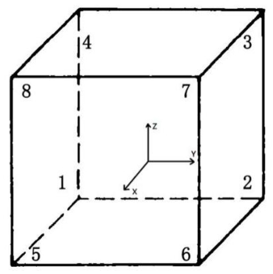
Figure 1.
3D hexahedron element and its coordinate system.
The interpolation function (or so-called shape function) N was given by Equation (13) [23].
The deduction of the equations of displacement and potential in terms of FEM was discussed. Here, the relationship between E and is shown in Equation (14) [28].
This could be rewritten as Equations (15)–(17).
where is the potential of the point and is the derivative of the vector of shape function N. Similarly, as for the displacement field, we used Equations (18)–(20).
Applying the Lagrange’s equation [29,30], the matrix form of the equilibrium equation was obtained as Equation (21).
The coefficients of the element stiffness matrix were as Equation (22).
where , , refer to element elastic matrix, nodal matrix, and piezoelectric matrix, respectively. Since the element type was a hexahedron element, the field of integration could be explicitly rewritten as In the context of the multi-node interpolation element, Gaussian interpolation was generally applied to accelerate the computing process [31]. The element equation was in a simple form, and therefore complete integration could be executed when going through the computing process.
The definition of shape function N and the derivative of and are shown in Supplementary CODE. 1.
The code referred to the assembly of matrix B and the assignment of the piezoelectric matrix. The integration procedure was realized, and the variable type was converted from “syms” to “double” for the later calculation steps (Supplementary CODE. 2). Finally, the data were stored in three-element matrices, which would be used in every iteration.
Sigmund [22] presented a topological optimization method and gave out a code in terms of 2D isotropic materials. In this work, the multi-objective optimization of voltage and stiffness was conducted by generalizing Sigmund’s method and code to 3-dimensional situations, as well as piezoelectric FEM calculation cases.
Based on Sigmund’s code, which proposed an assembly method under the two-dimensional method, this study extended the three-dimensional case. The coordinate system is shown in Figure 2. To facilitate analysis, a cuboid was selected as the model. The red dotted box indicates the original shape, and the black box shows the deformation result after stretching. The applied load of 20 N was set at 4,3,2 along the Z direction. This visual code was written by the author (the finite element model calculation part referred to the code of Liu [22] et al.), as shown in Supplementary CODE. 3.
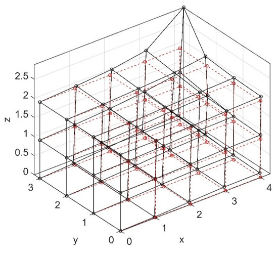
Figure 2.
The model and its deformation diagram.
The encoding of every node starts from (0, 0, 0); first along y, then along x, and finally along z, after finishing the encoding of the entire surface. To facilitate distinction, the colors of the surfaces with different z values have been distinguished. A unit was extracted separately, and its coding was studied, as shown in Figure 3. It could be seen that if the sequence numbers in the directions were , the total length in the three directions were , and the code numbers of the four points at the top of each unit could be represented by in Supplementary CODE. 4. Figure 4 shows the code values of eight points of a unit. After the code was expressed, the code value could then be used to express the degrees of freedom in the three directions of . The degree of freedom could be used to extract the displacement value and the potential value at the corresponding position of and , as shown in Supplementary CODE. 5. Liu [22] introduced another way of expressing three-dimensional units, however the method in this study was more readable and easier to understand, and so this method was used in this work.
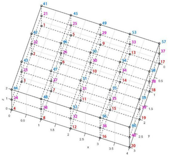
Figure 3.
Model coding schematic diagram.
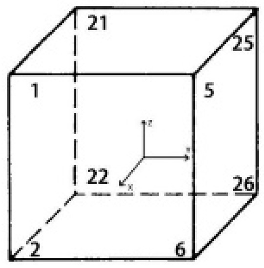
Figure 4.
Individual units and their numbers.
(4) Global stiffness matrix assembly
In this section, the global stiffness matrix was assembled by filling the corresponding element stiffness matrix in the corresponding position. The code representation is shown in Supplementary CODE. 6.
4. Optimizer Based on Optimal Criterion Method
The Optimality Criteria method, proposed by Sigmund, (also known as the OC method) is used. Then, the Lagrange multiplier method is used to derive the expression of the OC method as shown in Equation (23). For the sake of simplicity, since the expressions of MSE and SE are similar, MSE is omitted here.
Among them, is the cost function, also called the objective function.
and are Lagrange multipliers.
First, the objective function is derived as in Equation (24).
Furthermore, the equation mentioned above is substituted into the Lagrange function as shown in Equation (25).
The last term rewrites the derivative of F. Since F had nothing to do with the independent variable, the last term was equal to 0. This deforms the piezoelectric constitutive equation to get the Equations (26)–(29).
For the above formula, we multiplied U on the right side to eliminate the first two terms, multiplied U on the left side to eliminate the third term, and then moved the term to simplify and get formula Equation (30).
According to the nature of the optimization problem, the formula (30) could be set to 0 further to obtain Equation (31).
That was according to the fact shown in Equation (32) [32,33]:
A more general case was given by a NASA work [34], which defined a special case of the multiplier, , as shown in Equation (33).
is the derivation of the objective function in Equation (33), and is the accumulation of the Lagrangian multiplier and the corresponding product term. By setting to 1, stepwise iteration could be achieved to obtain the first derivative of 0, as shown in Equation (34):
The paper by Andreassen [35] pointed out that since the element was assumed to be a regular hexahedral with a constant volume when the finite element model was established, then the denominator term of the formula was always 1, and can be ignored.
Therefore, a heuristic update method could be obtained [22]. The upper and lower limits were added outside the formula, and some penalty factors were introduced to adjust the iteration speed (Equation (35)).
Among which, Equation (36) could be acquired.
Compared with the dichotomy in Sigmund’s OC method to find the lower limit of the iteration end of , the displacement of PZT-4 and the corresponding derivative value obtained in this study are both orders of smaller magnitude, so it was appropriate to reduce the lower limit and use , etc.
5. Size-Independent Filter
In the process of using the above method to calculate, it was found that as the grid size changed, the result of topology optimization changed. This was called grid dependence. One possible way was to use filters to filter the independent variables [22].
The expression of the filter was as Equations (37) and (38).
Among them, is the preset minimum filter radius, and the cells within this circle are filtered and set at 3 generally; is the distance between the center point and the filtered point.
6. Convergence Condition
There were three common convergence conditions [32,33]: (1) when the difference between the two objective functions is sufficiently small in two iterations, (2) when the difference between two iterations of the independent variable is sufficiently small, and (3) when the decrement of the function’s gradient between two iterations is sufficiently small. The above convergence termination conditions could be freely combined according to requirements, and the first two were used in this study.
7. Analysis of Topology Optimization
Solid-surface support, a volume fraction of 0.7, and an external load of 100 N were applied at the edge point of the cantilever beam, which was positive and upwards along the Y-axis. The structure of the facility is shown in Figure 5. The left surface is fixed, and the bottom is connected to the ground. The output voltage is measured through the top point.
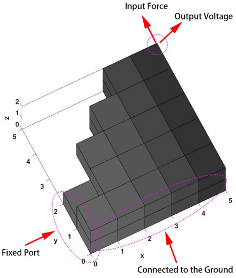
Figure 5.
3D model of the piezoelectric harvester.
Figure 6 shows the MSE–SE multi-objective optimization iteration diagram and model shape change diagram. Figure 6a shows the multi-objective value, Figure 6b shows the voltage, Figure 6c shows the SE value, and Figure 6d shows the MSE value. Topological optimization achieved the goal that the objective value could be reduced, and that the value of SE and MSE could be reduced and increased, respectively. Furthermore, the voltage was tested and the result showed that the voltage value was raised successfully. The value of MSE increased by 23.6%, the SE value decreased by 50.9%, and the voltage value increased by 30%. The bottom part of the diagram shows the corresponding structure diagram in each iteration state. It could be seen that the conclusion conformed to the expectation. The weakening connection between the structure and the base would help to improve the flexibility, thus increasing the voltage output. In addition, the x value at all points in the initialization was reduced to 70% of the original value. Therefore, the SE decline does not mean that the optimized structure was more robust (less compliant) than the original fully existing state with an initial x of 1, but rather, that the structure was adjusted to a better state under a fixed volume fraction of 0.7. Additionally, it can synchronously work as a sensor with a higher voltage output.
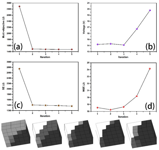
Figure 6.
Multi-objective optimization iteration diagram and model shape change diagram of mutual strain energy (MSE)–strain energy (SE). (a) Multi-objective figure. (b) Voltage output (c) SE value (d) MSE value.
Figure 7 shows the optimization results with SE as the only objective value. The SE objective value and the voltage value are shown in Figure 7a,b, respectively, and the corresponding model diagram is shown below. Compared to Figure 6, the above conclusions were confirmed. Namely, that the growing connection to the base increases the structural stiffness (and reduces compliance), and that the corresponding design of piezoelectric transducers supports the conclusion that adding a mass block at the end of the cantilever increases the voltage output. The decreasing voltage in Figure 7 confirms the effectiveness and necessity of MSE as the objective. With a higher voltage output, the piezoelectric harvester could work more efficiently.
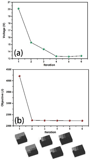
Figure 7.
Optimization iteration diagram and structure diagram with SE as the objective only. (a) Voltage output (b) objective value.
8. Conclusions
In this work, the three-dimensional topological optimization based on the piezoelectric transducer model of the cantilever was investigated. Using the Optimality Criteria, the structure optimization was realized with the voltage and stiffness as the multi-objective function. The calculations show that the voltage value was increased, and the global stiffness of the structure was also increased. Topological optimization achieved the goal of reducing the objective value. Furthermore, the voltage was tested, and the results demonstrate that the voltage value was raised successfully. With 70% of the origin volume, this bi-objective optimization increases the global stiffness by 50.9% and the voltage by 30%. As the iteration process shows, the increasing connection to the base increases the structural stiffness, and the corresponding design of piezoelectric transducers supports the conclusion that adding a mass block at the end of the cantilever can increase the voltage output. The comparison proves the superiority of bi-objective topology optimization. This lays the foundation for future piezoelectric transducer structural optimization. Moreover, this is also the first time a piezoelectric topology code has been shared.
Supplementary Materials
The following are available online at https://www.mdpi.com/2076-3417/10/19/6772/s1, CODE1 to CODE 7.
Author Contributions
Data curation, Y.L. and Z.H.; Software, Y.G. All authors have read and agreed to the published version of the manuscript.
Funding
This research was funded by National Natural Science Foundation of China (11602073, 11602149) and Natural Science Foundation of Heilongjiang Province of China (QC2018005), and the research is also supported by “the Fundamental Research Funds for the Central Universities” (Grant No.HIT.NSRIF.201821) and and the Fundamental Research Funds for the Central Universities under Grant No. DUT19RC(3)006. And The APC was funded by Natural Science Foundation of Heilongjiang Province of China (QC2018005).
Conflicts of Interest
The authors declare no conflict of interest.
Nomenclature
| Strain energy, the overall stiffness of the structure can be enhanced by minimizing | |
| Mutual strain energy, the voltage output can be enlarged by maximizing | |
| Correlation coefficient between and | |
| Global displacement matrix | |
| Global stiffness matrix | |
| Global displacement matrix under unit force | |
| Transposition of | |
| Element volume fraction | |
| Lower limit of x, commonly set as 0.001 | |
| Penalty fraction | |
| Element displacement under normal force | |
| Element displacement under unit force | |
| Global stiffness matrix | |
| Global dielectric matrix | |
| Global piezoelectric matrix | |
| Element matrix of | |
| Current total volume | |
| Origin volume | |
| Global volume fraction | |
| Global potential matrix | |
| Global charge matrix | |
| Force | |
| The x, y, z dimension of the cantilever | |
| Stress | |
| Elastic matrix under constant strain | |
| Strain | |
| Piezoelectric constant | |
| Electric field intensity | |
| Electric displacement | |
| Dielectric constant under constant electric field | |
| Derivative of vector of shape function N | |
| Lagrange function | |
| Cost function | |
| Preset minimum filter radius | |
| Cuboid dimension of x, y, z axis | |
| Accumulative account | |
| Interpolation function | |
| Lagrange multiplier | |
| Auxiliary multiplier | |
| Auxiliary parameter, for adjusting the speed and degree of iteration | |
| Distance between the center point and the filtered point |
References
- Da Silveira, A.R.G.; Daniel, G.B. Piezoelectric harvester for smart tilting pad journal bearings. Energy Convers. Manag. 2020, 205, 112338. [Google Scholar] [CrossRef]
- Wang, J.; Geng, L.; Zhou, S.; Zhang, Z.; Lai, Z.; Yurchenko, D. Design, modeling and experiments of broadband tristable galloping piezoelectric energy harvester. Acta Mech. Sin. 2020, 36, 592–605. [Google Scholar] [CrossRef]
- Belkourchia, Y.; Azrar, L.; Zeriab, E. Hybrid optimization procedure and application to location optimization of piezoelectric actuators and sensors for active vibration control. J. Appl. Math. Model. 2018, 62, 701–716. [Google Scholar]
- Liu, Y.; Hao, Z.W.; Yu, J.X.; Zhou, X.; Lee, P.S.; Sun, Y.; Mu, Z.; Zeng, F.L. A high-performance soft actuator based on a poly(vinylidene fluoride) piezoelectric bimorph. Smart Mater. Struct. 2019, 28, 055011. [Google Scholar] [CrossRef]
- Hu, K.; Li, H. Multi-parameter optimization of piezoelectric actuators for multi-mode active vibration control of cylindrical shells. J. Sound Vib. 2018, 426, 166–185. [Google Scholar] [CrossRef]
- Liu, Y.; Zhang, H.; Yu, J.X.; Huang, Z.Y.; Wang, C.; Sun, Y. Ferroelectric P(VDF-TrFE)/POSS nanocomposite films: Compatibility, piezoelectricity, energy harvesting performance, and mechanical and atomic oxygen erosion. RSC Adv. 2020, 10, 17377–17386. [Google Scholar]
- Silva, E.C.N.; Fonseca, J.S.O.; De Espinosa, F.M.; Crumm, A.T.; Brady, G.A.; Halloran, J.W.; Kikuchi, N. Design of piezocomposite materials and piezoelectric transducers using topology optimization—Part I. Arch. Comput. Methods Eng. 1999, 6, 117–182. [Google Scholar] [CrossRef]
- Silva, E.C.N.; Nishiwaki, S.; Kikuchi, N. Design of piezocomposite materials and piezoelectric transducers using topology optimization—Part II. Arch. Comput. Methods Eng. 1999, 6, 191–222. [Google Scholar] [CrossRef]
- Ray, M.C.; Mallik, N. Finite Element Analysis of Smart Structures Containing Piezoelectric Fiber-Reinforced Composite Actuator. AIAA J. 2004, 42, 1398–1405. [Google Scholar] [CrossRef]
- Zheng, B.; Chang, C.J.; Gea, H.C. Topology optimization of energy harvesting devices using piezoelectric materials. Struct. Multidiscip. Optim. 2009, 38, 17–23. [Google Scholar] [CrossRef]
- Homayouni-Amlashi, A.; Mohand-Ousaid, A.; Rakotondrabe, M. Topology optimization of 2DOF piezoelectric plate energy harvester under external in-plane force. J. Micro-Bio Robot. 2020, 16, 65–77. [Google Scholar] [CrossRef]
- Chamoin, L.; Nguyen, H.; Zhuang, X. Topology Optimization of 1-3 Piezoelectric Composites; Springer: Stuttgart, Germany, 2020. [Google Scholar]
- Creaco, E.; Galuppini, G.; Campisano, A.; Ciaponi, C.; Pezzinga, G. A Bi-Objective Approach for Optimizing the Installation of PATs in Systems of Transmission Mains. Water 2020, 12, 330. [Google Scholar] [CrossRef]
- Rupp, C.J.; Evgrafov, A.; Maute, K.; Dunn, A.P.M.L. Design of Piezoelectric Energy Harvesting Systems: A Topology Optimization Approach Based on Multilayer Plates and Shells. J. Intell. Mater. Syst. Struct. 2009, 20, 1923–1939. [Google Scholar] [CrossRef]
- Kogl, M.; Silva, E.C.N. Topology optimization of smart structures: Design of piezoelectric plate and shell actuators. Smart Mater. Struct. 2005, 14, 387–399. [Google Scholar] [CrossRef]
- Carbonari, R.C.; Silva, E.C.N.; Nishiwaki, S. Optimum placement of piezoelectric material in piezoactuator design. Smart Mater. Struct. 2007, 16, 207–220. [Google Scholar] [CrossRef]
- Ha, Y.; Cho, S. Design sensitivity analysis and topology optimization of eigenvalue problems for piezoelectric resonators. Smart Mater. Struct. 2006, 15, 1513–1524. [Google Scholar] [CrossRef]
- Kiyono, C.Y.; Silva, E.; Reddy, J. Design of laminated piezocomposite shell transducers with arbitrary fiber orientation using topology optimization approach. Int. J. Numer. Methods Eng. 2012, 90, 1452–1484. [Google Scholar] [CrossRef]
- Sivapuram, R.; Dunning, P.D.; Kim, H.A. Simultaneous material and structural optimization by multiscale topology optimization. Struct. Multidiscip. Optim. 2016, 54, 1267–1281. [Google Scholar] [CrossRef]
- Sosnovik, I.; Oseledets, I. Neural networks for topology optimization. Russ. J. Numer. Anal. Math. Model. 2019, 34, 215–223. [Google Scholar] [CrossRef]
- Zhu, J.; Zhang, W.-H.; Xia, Q. Topology Optimization in Aircraft and Aerospace Structures Design. Arch. Comput. Methods Eng. 2015, 23, 595–622. [Google Scholar] [CrossRef]
- Sigmund, O. A 99 line topology optimization code written in Matlab. Struct. Multidiscip. Optim. 2001, 21, 120–127. [Google Scholar] [CrossRef]
- Liu, K.; Tovar, A. An efficient 3D topology optimization code written in Matlab. Struct. Multidiscip. Optim. 2014, 50, 1175–1196. [Google Scholar] [CrossRef]
- Abdalla, M.; Frecker, M.; Gürdal, Z.; Johnson, T.; Lindner, D.K. Design of a piezoelectric actuator and compliant mechanism combination for maximum energy efficiency. Smart Mater. Struct. 2005, 14, 1421. [Google Scholar] [CrossRef]
- Huang, S.C.; Lan, G.J. Design and fabrication of a micro-compliant amplifier with a topology optimal compliant mechanism integrated with a piezoelectric microactuator. J. Micromechanics Microengineering 2006, 16, 531. [Google Scholar] [CrossRef]
- Luo, Z.; Chen, L.; Yang, J.; Zhang, N.; Abdel-Malek, K. Compliant mechanism design using multi-objective topology optimization scheme of continuum structures. Struct. Multidiscip. Optim. 2005, 30, 142–154. [Google Scholar] [CrossRef]
- De Almeida, B.V.; Pavanello, R. Topology Optimization of the Thickness Profile of Bimorph Piezoelectric Energy Harvesting Devices. J. Appl. Comput. Mech. 2019, 5, 113–127. [Google Scholar]
- Hladky-Hennion, A.-C.; Dubus, B. Finite Element Analysis of Piezoelectric Transducers; Springer: Berlin/Heidelberg, Germany, 2008; pp. 241–258. [Google Scholar]
- Detwiler, D.T.; Shen, M.H.H.; Venkayya, V.B. Finite element analysis of laminated composite structures containing distributed piezoelectric actuators and sensors. Finite Elements Anal. Des. 1995, 20, 87–100. [Google Scholar] [CrossRef]
- Tzou, H.S.; Tseng, C.I. Distributed Modal Identification and Vibration Control of Continua: Piezoelectric Finite Element Formulation and Analysis. J. Dyn. Syst. Meas. Control. Trans. Asme 1991, 113, 500–505. [Google Scholar] [CrossRef]
- Silva, E.C.N.; Kikuchi, N. Design of piezoelectric transducers using topology optimization. Smart Mater. Struct. 1999, 8, 350–364. [Google Scholar] [CrossRef]
- Luo, Z.; Chen, L.-P.; Yang, J.; Zhang, N. Multiple stiffness topology optimizations of continuum structures. Int. J. Adv. Manuf. Technol. 2006, 30, 203–214. [Google Scholar] [CrossRef]
- Luo, Z.; Yang, J.; Chen, L.-P.; Zhang, N.; Abdel-Malek, K. A new hybrid fuzzy-goal programming scheme for multi-objective topological optimization of static and dynamic structures under multiple loading conditions. Struct. Multidiscip. Optim. 2006, 31, 26–39. [Google Scholar] [CrossRef]
- Patnaik, S.N.; Guptill, J.D.; Berke, L. Merits and limitations of optimality criteria method for structural optimization. Int. J. Numer. Methods Eng. 1995, 38, 3087–3120. [Google Scholar] [CrossRef]
- Andreassen, E.; Clausen, A.; Schevenels, M.; Lazarov, B.S.; Sigmund, O. Efficient topology optimization in MATLAB using 88 lines of code. Struct. Multidiscip. Optim. 2010, 43, 1–16. [Google Scholar] [CrossRef]
© 2020 by the authors. Licensee MDPI, Basel, Switzerland. This article is an open access article distributed under the terms and conditions of the Creative Commons Attribution (CC BY) license (http://creativecommons.org/licenses/by/4.0/).