Abstract
Thin-walled conical parts with variable-section are usually made of superalloy material, with poor plasticity and complex forces, which are difficult to form and control. In this research, a thin-walled conical casing of superalloy GH1140 with variable-section is studied; the real stress–strain curve of the material is fitted and the load-displacement curves of superalloy GH1140 are obtained through a universal testing machine. To clarify the equivalent stress distribution on the upper surface of the thin-walled casing during the forming process and after unloading the rotary wheel, the finite element model of the thin-walled conical casing during the spinning forming process is established with the Simufact Forming finite element analysis software. The effects of processing parameters, such as the mandrel rotational speed ω, the roller feed ratio f and the gap deviation rate δ between the roller and mandrel, on the spinning forming load were obtained. The distribution and numerical trend of the tangential residual stress after forming were detected by X-ray diffraction, and the causes of defects such as flange instability were analyzed. The results of the forming test and the test of residual stress conform well with the simulation, which verifies the stability of the model. The research provides a theoretical basis for improving the forming quality of thin-walled parts with variable-section.
1. Introduction
Metal spinning, as an advanced processing technology, is widely applied in the field of metal plastic forming. It has advantages such as no cutting or less cutting in the stretching process [1]. The spinning forming of thin-walled revolving parts has the advantages of high manufacturing accuracy, low energy consumption and low processing cost. Especially during the forming process, the metal flows along the tangential direction of the forming parts, the internal grain of the metal is not distorted, and the residual stress is small, which makes the spinning process better than other forming methods [2,3,4,5]. Thin-walled parts, a complex rotating part with thin wall thickness and large diameter, are widely used as external loading parts of aero-engine casings. They usually work under long-term high temperature, high pressure and alternating loading. The material is usually superalloy, which is difficult to form and control. After forming, there are varying degrees of residual stress in the interior, which has become a potential danger for aero-engine service. How to improve the spinning forming quality of thin-walled conical parts with variable-section has become a research hotspot in China and abroad.
In order to improve the spinning quality of thin-walled conical parts with variable-section and to improve their service life, many scholars at home and abroad have studied different aspects of the spinning process. Liu et al. [6] formed a magnesium alloy conical part with a ring reinforcement by wedge extrusion and analyzed the variation law of equivalent strain. Xu et al. [7] studied the effects of the material self-plasticity on the spinning forming quality with LF2, LF6 and LF21 aluminum alloy as the research objects. Wang et al. [8] and Lv et al. [9] established a model of spinning for processing double conical parts and analyzed the influence of the forming parameters on stress–strain, which provides ideas for spinning the conical parts more efficiently. Zhang et al. [10] and Davidson et al. [11] used the method of combining the experiment of spinning cylindrical parts and finite element simulation to analyze the effect of process parameters on the surface residual stress in spinning cylindrical parts. They found that residual stress fluctuated with the change of process parameters. Wang [12] and Wang et al. [13] studied the spinning forming of a connecting rod bushing and head, and analyzed the mechanism of residual stress. They respectively used the X-ray method in nondestructive testing and the residual stress release of small holes in destructive testing to measure the surface residual stress of the workpiece. Romero et al. [14] and Klocke et al. [15] proved by hot power spinning high-strength steel that hot spinning could reduce the residual stress of the parts. Dai et al. [16] analyzed the influence of process parameters on wall thickness deviation, ellipticity, straightness and roughness in the flow spinning of 1J50 soft magnetic alloy. He [17] studied the distribution and variation law of equivalent stress–strain in the power spinning process of a TA15 titanium alloy cylindrical tube and the main structural parameters on equivalent stress–strain. Wu et al. [18] analyzed the influence of process parameters on the forming quality during the first pass and second pass spinning forming of thin-walled conical parts. They proposed to choose a larger gap deviation rate of the roller to avoid wrinkling and cracking.
Based on the above-mentioned research, it can be seen that the existing study mainly focuses on the plastic state, stress, residual stress and so on. There is no systematic research on the influence of process parameters on the forming loading of thin-walled conical parts with variable-section. In this paper, the superalloy GH1140 thin-walled conical casing with variable-section is taken as the research object to study the influence of forming process parameters on the forming load. It provides a theoretical basis for improving the forming quality of variable-section thin-walled parts.
2. The True Stress-Strain Relationship of Superalloy GH1140
The premise of the plastic forming problem is described with the plastic condition and constitutive equations. The functional relationship of these two equations is related to the shape and material properties of the workpiece, but is independent of the stress state [19]. The true stress–strain curve of the superalloy GH1140 is established by the uniaxial uniform tensile test method.
According to GB/T 228.1-2010, the superalloy GH1140 sheet with thickness of 2 mm should be cut to get the sample [20]. The sample structure before and after the experiment is shown in Figure 1. Five groups of tensile tests with the conditions of 3 mm/min moving speed and 20 °C normal temperature were carried out on the MTS600 tensile sample machine (Jinan MTS Testing Technology Co., Ltd, Jinan, China). The nominal stress–strain curve is obtained, as shown in Figure 2.

Figure 1.
Tensile test sample of the GH1140 superalloy: (a) the tensile test sample structure; and (b) the stretched test sample.
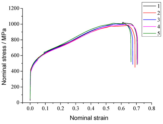
Figure 2.
Nominal stress–strain curve of the GH1140 superalloy.
The nominal stress–strain curve reflects that the stress of deformation continues to increase with the increase of displacement, before the metal enters plastic deformation. The strengthening effect of the material is dominant. After entering plastic deformation, the cross-sectional area decreases, the stress concentration appears and the stress value decreases. Therefore, the nominal stress–strain curve does not apply to the tensile process that reflects the changing cross-section of the sample. It is necessary to further derive the true stress-true strain curve.
Based on the above formulas, the true stress–strain curve of the sample can be obtained by integrating the five samples′ nominal stress–strain curves, as shown in Figure 3.
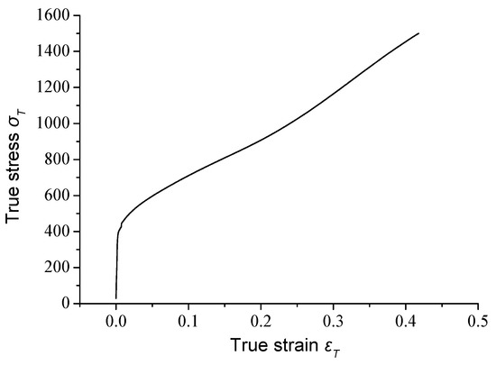
Figure 3.
True stress–strain curve of the GH1140 superalloy.
The elastoplastic equations of metal materials have nonlinear properties. The strength coefficient K and strain hardening coefficient n are fitted according to elastoplastic models, which describe the plastic flow behavior of the material. However, the applicability of the model to the obtained tensile test curves is different, so the model needs to be chosen according to the fitting results [4]. As shown in Equations (3)–(6), four elastoplastic models were proposed [21,22,23,24]. The corresponding fitting results are shown in Table 1.

Table 1.
Fitting equation of the stress–strain curve of the superalloy GH1140.
Hollomon:
Ludwik:
Voce:
Ludwigson:
Among them, SSE is the sum of squares due to error. It refers to the total deviation of the sample data from the regression equation. RMSE is root mean squared error. DFE is the degrees of freedom error. The coefficient of determination R indicates the fitting degree of the regression equation corresponding to the sample data, which is used to judge the accuracy of the fitting equation. The closer the R value is to 1, the better the fitting effect. Therefore, the true stress-strain equation fitted by the Ludwik model is selected, as shown in Equation (7).
where expresses the true stress during uniaxial tension and expresses the true strain during uniaxial tension.
The comparison between the fitting curve and the true stress–strain curve is shown in Figure 4. The fitting accuracy is high, which verifies the correctness of the model in this paper.
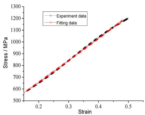
Figure 4.
Comparison of the true stress–strain curves and the fitted curves of the superalloy GH1140.
3. Mechanical Model and Finite Element Analysis
3.1. Mechanical Model
When the external load during the metal spinning deformation is different, the stress state is different, so the plasticity also varies. The sheet metal is discretized and divided into independent blocks. The stress state of each block is expressed by three principle stresses. The direction and nature of the principle stress varies with the force. The mechanical model of shear spinning is shown in Figure 5.
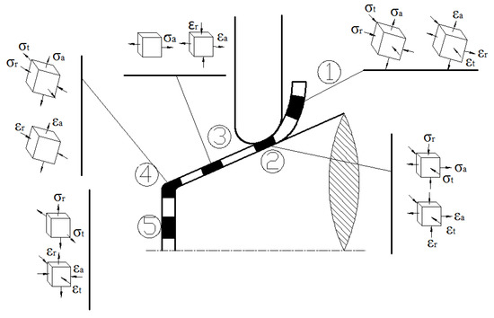
Figure 5.
Mechanical model of shear spinning.
According to existing theories and experience, the function of spinning force P can be expressed as:
where:
- t0—the thickness of the blank
- σs—the yield limit of the material
- φt—the thinning rate of the blank
- f—the feed per revolution of the roller
- rp—the working radius of the roller
- αρ—the contact angle of the roller
- α—the half cone angle of the mandrel
- D—the diameter of the parts
- Δt—the clearance deviation.
During the spinning forming process, the direction of the spinning force P changes continuously. According to the rotation direction of the mandrel, the feeding direction of the roller and the axial direction of the blank, the spinning force P can be decomposed into three perpendicular components Pt, Pr and Pz, which are conducive to measurement and data extraction. The relationship between them in the spatial coordinates system is shown in Equation (9):
where, Pr expresses the radial component force, which is perpendicular to the mandrel axis. Pz expresses the axial component force, which is parallel to the mandrel axis. Pt expresses the tangential component force, which is tangent to the workpiece generatrix.
The radial force Pr and the axial force Pz are mainly supplied by the feed force of the roller, transmitted from the drive system to the spindle of the machine tool, and then to the roller frame. The forming force of the blank is directly counteracted by the whole mechanism of the supporting part of the roller. The stiffness, strength and stability of the supporting mechanism will be affected by fluctuation, maximum value and mutation. Therefore, the radial force and the axial force contribute to the selection of forming equipment and the optimization of the supporting mechanism.
3.2. Establishment of Finite Element (FE) Model
As shown in Figure 6, the FE simulation model of the thin-walled conical part with variable-section during spinning is established by Unigraphics NX, which includes roller, blank, mandrel and back-plate. Unigraphics NX software is a flexible and powerful integrated solution that delivers the next generation of design, simulation, and manufacturing solutions. The blank is fixed on the top of the mandrel by the back-plate, while the mandrel and back-plate are rotated at a fixed speed; they drive the blank to rotate at the same time. The rollers on both sides are fed according to the preset track, driven passively by the blank, and they apply pressure to the blank. The FE model in STL format was imported into Simufact.Forming, which is an advanced material processing and heat treatment process simulation optimization software. The blank selected in this paper is a circular sheet with a thickness of 2 mm and a diameter of 250 mm. The material in the top area of the blank does not participate in the deformation process, so the model of the blank is simplified as a circular blank with a hole in the center of the top. The volume of the blank becomes smaller, and the number of meshes is reduced, thus shortening the simulation time. The material of the blank used in the simulation is superalloy GH1140. It is defined as elastoplastic and it is divided by a Hexahedral mesh cell. The mandrel, roller and back-plate are both considered as rigid. In order to reduce unnecessary simulation time, the friction heat generated between the roller and blank during the forming process is neglected. The ambient temperature, blank temperature and mandrel temperature are set to 25 °C. The relative parameters of the simulation are as follows: the rotary speed is 250 r/min, the feed speed is 1.0mm/r, the friction coefficient is 0.5 and the gap deviation rate is 5%.
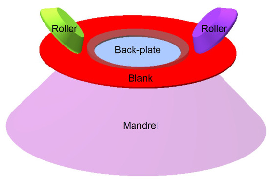
Figure 6.
The finite element model of spinning.
3.3. Finite Element Analysis
Based on the above-mentioned finite element model, the spinning process is divided into six sections. According to the equivalent stress distribution of different forming stages in Figure 7, the maximum value of the equivalent stress is always located at the contact area between the roller fillet and the material. The position changes with the feed of the roller relative to the material. The equivalent stress behind the roller is smaller and tends to be stable in the initial forming stage, but stress concentration occurs after the discontinuous wall thickness area.
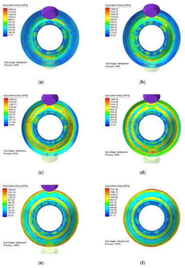
Figure 7.
Equivalent stress distribution of the outer surface in each forming stage: (a) 20% forming process; (b) 40% forming process; (c) 60% forming process; (d) 80% forming process; (e) 100% forming process; and (f) after the roller unloading.
With the spinning process going on, the equivalent stress in the formed area behind the roller still keeps a large value, which is more obvious when the roller feed ratio is large. This is because the roller is feeding at a faster speed relative to the material, and the metal flow speed is relatively slow. The influence of tensile effect is obvious. In the unformed area, the phenomenon of stress concentration is more obvious, because the flange is in a torque stress state and the additional bending stiffness aggravates the difficulty of the metal flow. In addition, the point contact between the roller and the material leads to uneven deformation, so the equivalent stress fluctuates. At the top of the conical part, the back-plate has a fixed role on the sheet metal and also participates in the transfer of forming torque, so the stress concentration appears at the edge of the back-plate, but the stress near the center is basically zero.
4. Effect of Process Parameters on Forming Load
4.1. Determination of Process Parameters
The spinning force referred to in this study is the reaction force of the plate to the roller, mainly because the forming force of the plate itself cannot be measured. The force value of the right-hand roller in the model is selected as the spinning force to analyze. In order to study the effects and trends of the various process parameters on the forming load, the test plans and results of the force are shown in Table 2. The larger the range value R is, there is a more significant effect of this factor on the experimental index. It can be concluded that the greatest impact on the spinning force maximum is the roller feed ratio f, followed by the mandrel rotational speed ω and the gap deviation rate δ between the roller and mandrel. The effect of the roller feed ratio f is also highly significant when considering the influence of the single factor variation on the maximum spinning force. The optimal combination of process parameters is the 18th group of process parameters A5B2C1. As shown in Table 3, the single factor variable test plan is designed by the simulation of the spinning force maximum change of the optimal process parameters.

Table 2.
Test plans and results of the force.

Table 3.
The single factor variable test plan.
4.2. Effects of Mandrel Rotational Speed on Forming Load
The effect of the mandrel rotational speed on the spinning force is shown in Figure 8. When the spindle speed is increased under the condition of constant feed ratio, the spinning force is basically stable because the volume of materials involved in deformation does not change during the same deformation time. The overall spinning force is basically unchanged with the increase of the roller rotational speed when the roller feed ratio is 0.6, 1.0 and 1.4, but the fluctuation of the spinning force is different.
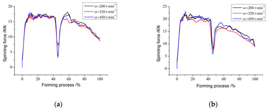
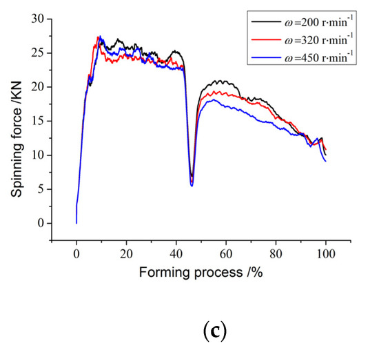
Figure 8.
The change of the rotational force when f is the same: (a) f = 0.6 mm/r; and (b) f = 1.0 mm/r; (c) f = 1.4 mm/r.
When the rotational speed is 200 r/min, the difference between the peak and trough of the spinning force is the smallest, which reduces the possibility of the dangerous section rupture. Correspondingly, due to the low rotational speed, the contact between the roller and blank is slow after entering conventional spinning. Under the excessive thinning and friction, the spinning force maximum increases rapidly and the wave peak is obvious. The trough at the junction is similar when the rotational speed is 320 r/min and 400 r/min, but the fluctuation of the spinning force is larger in the conventional spinning stage when the rotational speed is 320 r/min.
When the rotary feed ratio is 1.0 mm/r and the rotational speed increases from 320 r/min to 450 r/min, the deformation time of the metal is shortened. At the same time, the sheet is repeatedly rolled, resulting in excessive thinning and increasing spinning force. As a whole, the deformation rate of the metal accelerates at the same time. The numerical difference between shear spinning and conventional spinning is obvious. Moreover, the average spinning force of the shear spinning stage is obviously larger than the value when the feed ratio is 0.6 mm/r. The average spinning pressure in the conventional spinning stage is approaching. The spinning force increases further when the feed ratio is 1.0 mm/r. When the rotational speed is 450 r/min, the speed of the mandrel is matched with that of the rotary feed ratio. Compared with the other two sets of rotational speeds, the spinning force of the conventional spinning stage decreases.
4.3. Effects of Roller Feed Ratio on Forming Load
The effect of the roller feed ratio on the spinning force is shown in Figure 9. Under the condition of constant mandrel rotational speed, increasing the roller feed ratio will lead to an increase of the strain rate and the amount of metal formed in the same time, so the spinning force also increases. This is because the mechanism of plastic deformation is complicated; it requires a certain amount of time to complete. The effect of the roller feed ratio f is highly significant when considering the influence of the single factor variation on the spinning force maximum.
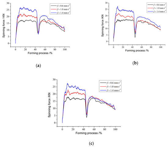
Figure 9.
The change of the spinning force when ω is the same: (a) ω = 200 r/min; (b) ω = 320 r/min; and (c) ω = 450 r/min.
In general, when the rotary feed ratio is 0.6 mm/r, the spinning force in the shear spinning stage is similar to that in the conventional spinning stage; when the rotary feed ratio is 1.0 mm/r, the spinning force changes steadily; when the rotary feed ratio is 1.4 mm/r, the spinning pressure increases as a whole, and the average spinning force difference between the shear spinning and conventional spinning is the largest.
At the start of the spinning stage of shear spinning, the spinning pressure rises steadily when the rotary speed is 200 r/min and 320 r/min, but there is an obvious peak at 450 r/min, due to the rapid change of the metal stress and strain and the impact on the roller. During the transition from shear spinning to conventional spinning, when the feed rate is 0.6 mm/r, the roller contacts with the sheet again. When the mandrel speed is 200 r/min, the lower rotary speed cannot provide enough friction force to rotate the roller, resulting in poor feed and metal flow obstruction, which makes the spinning force fluctuate greatly; when the feed rate is 1.4 mm/r, the rotary speed of the mandrel is low, and the roller can only feed repeatedly once during a circle. The sheet metal thins excessively, so fluctuation also appears.
As shown in Figure 10, when the gap deviation rate is 2.5% and the rotary speed is 320 r/min, the spinning force in the power spinning stage increases with the increase of the roller feed ratio, and the fluctuation amplitude increases. In the conventional spinning stage, the spinning force instead decreases, and the amplitude of fluctuations decreases. When the clearance deviation rate is 2.5% and the rotary speed is 450 r/min, the spinning pressure in the power spinning stage increases with the increase of the roller feed ratio. In the initial contact stage between the roller and the blank, the material involved in deformation increases and the material flow rate decreases because of the large feed ratio. In addition, the material deformation resistance and the roller feed resistance on different cross-sectional areas are both different, causing a large fluctuation of the spinning force. Therefore, the wall thickness uniformity of the formed conical part reduces, which causes an adverse effect on the stable operation of the spinning machine. In the conventional spinning stage, the extreme value and the change trend of the spinning force are both the same, but the fluctuation of the spinning force is small when the roller feed ratio is 1.4 mm/r, which proves that the roller feed ratio matches the mandrel rotational speed.
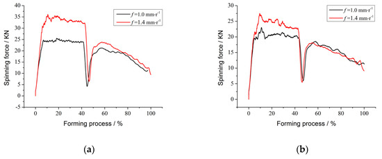
Figure 10.
The change of the spinning force when δ = 2.5%: (a) ω = 320 r/min; and (b) ω = 450 r/min.
4.4. Effects of Gap Deviation Rate on Forming Load
As shown in Figure 11, under the same mandrel rotational speed and roller feed ratio, with an increase of the clearance deviation rate, the spinning force does not change as a whole. When the gap deviation rate is positive, the deformation state of the material is the combination of shear and tension. The formed part is not well molded, and local thinning is prone to occur under tensile stress. At a zero gap deviation rate, the deformation of the material is pure shear, which is the most stable deformation process.
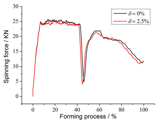
Figure 11.
The change of the spinning force when δ changes.
5. Spinning Experiment
5.1. Test Plan
The process parameters for the spin-formed conical is shown in Table 4. Nine sets of orthogonal tests were carried out in this paper with the BXQX800II CNC spinning machine (Taizhou Boxiang Spinning Machine Tool Co., Ltd, Taizhou, China). The GH1140 superalloy blank with a diameter of 250 mm and a thickness of 2 mm were spin-formed at normal temperature. The applicability of the FEM and the reliability of the optimization scheme are verified by the comparison of simulation and experiment results.

Table 4.
Process parameters for the spin-formed conical.
5.2. Comparison Analysis
5.2.1. Forming Comparison of Spinning Parts
The comparison between the finite element simulation and the experimental formed results is shown in Figure 12. The results are basically consistent.
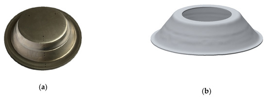
Figure 12.
Comparison of the test samples and the simulated samples: (a) the test formed part; and (b) the simulation formed part.
In order to validate the computer simulation, the experimental part cut along the thickness direction is compared with the simulation cross-sectional view, as shown in Figure 13. The die-attachment effect is better at the beginning of the deformation. It verifies the reliability of the spinning finite element model.
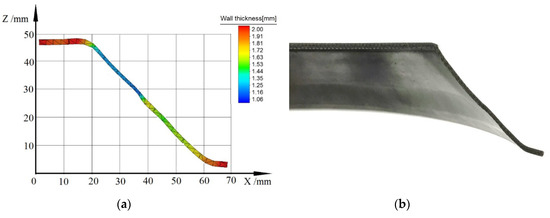
Figure 13.
Comparison of wall thickness: (a) simulation cross-sectional part; and (b) cross-section of the experimental part.
5.2.2. Measurement and Simulation of Residual Stress
The 300W XRD Portable residual stress measuring instrument is used for the measurement. As shown in Figure 14, the MG40 goniometer and bracket can be used to realize the displacement change in the direction of the Z axis. The above-mentioned instruments are from Proto, Canada. The range of the 2θ diffraction angle is from 110° to 171°. The Mn target and the Mn-Kα radiation are used in the measurement.
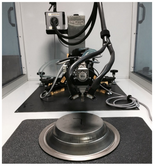
Figure 14.
Residual stress testing process.
X-ray methods have many applications, such as dimensional metrology for the measurement of various micro-features and the use of X-ray computed tomography (XTC) to characterize the pores inside the particles [25]. XCT is a reliable and accurate technique for pore evaluation in manufactured parts as a non-destructive method and enables the pore shape, position and size distribution analysis. The X-ray method can also be used to measure residual stress, which uses measures the diffraction phenomenon of X-rays incident on the crystal. The tube pressure of the X-ray tube in this research is 25 KV, the pipe current is 5 Ma, and the range of the Ψ angle is from 0° to 30°.
According to the regulation of GB/T 7704-2017, three cross sections are uniformly taken on the surface of the conical part, and the positions of the intersections are marked by points. The location of the samples is shown in Figure 15.
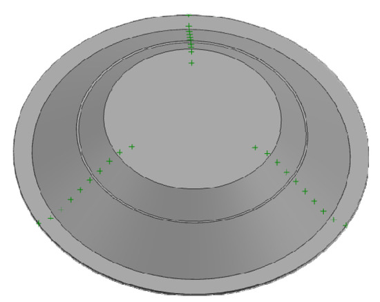
Figure 15.
Sample position of residual stress detection.
As shown in Figure 16, the residual stress curve measured in the experiments shows that the trend of residual stress on the outer surface of three sections are the same. The comparison between spline 1 and the residual stress of the simulation output shows that the simulation is consistent with the experimental result.
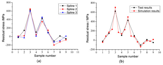
Figure 16.
Comparison of residual stress measured by experiment and simulation: (a) residual stress of three splines; (b) residual stress between the test results and the simulation results.
6. Conclusions
The greatest impact on the spinning force maximum is the roller feed ratio f, followed by the mandrel rotational speed ω and the gap deviation rate δ between the roller and mandrel.
Under the condition of constant mandrel rotational speed, increasing the roller feed ratio will lead to an increase of the strain rate and the amount of metal formed in the same time, which will increase the spinning force.
The mandrel rotational speed has little effect on the spinning force. The spinning force is basically unchanged with an increase of the roller rotational speed when the roller feed ratio is 0.6, 1.0 and 1.4, but the fluctuation of the spinning force is different.
With an increase of the gap deviation rate, the spinning force does not change as a whole. At zero gap deviation rate, the deformation of the material is pure shear, which is the most stable deformation process.
The forming experiments and the residual stress test show that the simulation and experiment results are basically consistent, which further verifies the reliability of this study.
Author Contributions
Conceptualization, Y.X., X.S., Y.Z. and Z.L.; methodology, Y.X., X.S. and Z.L.; software, Y.X. and Z.L.; validation, Y.X., X.S., Y.Z. and Z.L.; formal analysis, Y.X., X.S., Y.Z. and Z.L.; investigation, Y.X., X.S., Y.Z. and Z.L.; data curation, Y.X., X.S., Y.Z. and Z.L.; writing—original draft preparation, Y.X., X.S., Y.Z. and Z.L.; writing—review and editing, Y.X., X.S., Y.Z. and Z.L.; visualization, Y.X., X.S., and Y.Z.; supervision, Y.X., X.S., and Z.L. All authors have read and agreed to the published version of the manuscript.
Funding
This research was funded by Zhejiang Provincial Natural Science Foundation (grant number: LZ17E050001) and the National Natural Science Foundation of China (grant number: 51975301).
Acknowledgments
The authors gratefully acknowledge the Zhejiang Provincial Key Lab of Part Rolling Technology in Ningbo University, China. We would like to express our heartfelt gratitude to Chaoqun Jiang from Shanghai International Studies University for her proofreading, grammar checking and English language revision of this article.
Conflicts of Interest
The authors declare no conflict of interest. The funders had no role in the design of the study; they had no role in the collection, analyses, or interpretation of data; and they had no role in the writing of the manuscript, nor in the decision to publish the results.
References
- Wang, C.H.; Liu, K.Z. Spinning Technology; China Machine Press: Beijing, China, 1986. [Google Scholar]
- Huang, L.; Zeng, R.; Zhang, X.T.; Li, J.J. Study on plastic deformation behavior of hot splitting spinning of TA15 titanium alloy. Mater. Design 2014, 58, 465–474. [Google Scholar] [CrossRef]
- Zhang, C.; Yang, H.C.; Han, D.; Wang, X.J.; Mo, R.; Lu, X.R.; Gong, J.S. Applications and development of titanium alloys spinning technology in domestic aerospace field. J. Solid Rocket Technol. 2013, 36, 127–132. [Google Scholar]
- Xia, Q.X.; Xiao, G.F.; Long, H.; Sheng, X.F. A review of process advancement of novel metal spinning. Int. J. Mach. Tools Manuf. 2014, 85, 100–121. [Google Scholar] [CrossRef]
- Fan, S.Q.; Hua, Y.; Zhao, S.D.; Li, F.D. Dynamics simulation on double-roller clamping spinning device driven by multi-motor. Forg. Stamp. Technol. 2019, 44, 93–98. [Google Scholar]
- Liu, W.J.; Wu, Y.J.; Xue, Y.; Zhang, Z.M. Study on Extrusion Forming Process Parameters of AZ80 Magnesium Alloy for Conical Parts with Inner Ring Rib. Hot Work. Technol. 2015, 44, 119–122. [Google Scholar]
- Xu, W.C.; Shan, D.B.; Lu, Y.; Li, C.F. Research on the multi-pass shear spinning technology of small-angle conical workpieces. Mater. Sci. Technol. 2004, 12, 33–40. [Google Scholar]
- Wang, H.J.; Liu, Q.K.; Wang, Q.S.; Han, Y. FEM analysis of stress and strain fields for double conical part spinning. Forg. Stamp. Technol. 2011, 36, 152–158. [Google Scholar]
- Lv, H.J.; Yu, W.Y.; Wang, Q.; Li, Q.J.; Shan, D.B. FEM numerical simulation of spinning processing for TC4 alloy. J. Tianjin Polytech. Univ. 2007, 26, 59–65. [Google Scholar]
- Zhang, T.; Li, X.H.; Luo, Y.Z.; Chang, S.W.; Wei, Z. Influence of process parameters on surface residual stress for thin-wall cylindrical part in the reduction spinning. Forg. Stamp. Technol. 2017, 42, 47–53. [Google Scholar]
- Davidson, M.J.; Balasubramanian, K.; Tagore, G.R.N. Experimental investigation on flow-forming of AA6061 alloy-A Taguchi approach. J. Mater. Process. Technol. 2008, 200, 283–287. [Google Scholar] [CrossRef]
- Wang, Y. Experimental Research on the Influence of Process Parameters of the Power Spinning Connecting Rod Bushing on the Dimensional Precision and the Residual Stress. Master’s Thesis, North University of China, Taiyuan, China, 2016. [Google Scholar]
- Wang, Z.C.; Zhong, H.T.; Chen, G.L. An Experimental Research on Residual Stress in Rotary Extruding Head. Press. Vessel Technol. 1993, 10, 47–51. [Google Scholar]
- Romero, P.; Otero, N.; Cabrera, J.M.; Masagué, D. Laser assisted conical spin forming of dual phase automotive steel. Experimental Demonstration of Work Hardening Reduction and Forming Limit Extension. Phys. Procedia 2010, 5, 215–225. [Google Scholar] [CrossRef]
- Klocke, F.; Wehrmeister, T. Laser-Assisted metal spinning of challenging materials. Procedia Eng. 2004, 81, 2385–2390. [Google Scholar] [CrossRef]
- Dai, G.Y.; Xia, Q.X.; Cheng, X.Q.; Zhu, N.Y. Research on forming quality of cylindrical part of soft magnetic alloy 1J50 in flow spinning. Forg. Stamp. Technol. 2017, 42, 60–65. [Google Scholar]
- He, Y. Research on Power Spinning Forming of Titanium Alloy Tube. Master’s Thesis, Chang’an University, Xi’an, China, 2015. [Google Scholar]
- Wu, T.C.; Zhan, M.; Jiang, H.B.; Gu, C.G.; Yang, H. Exploring effect of spinning gap on forming quality of second pass spinning of large-sized complicated thin-walled shell. J. Northwest Polytechnical. Univ. 2011, 29, 74–81. [Google Scholar]
- Qiu, X.G.; Zhang, X.H.; Tang, J.; Tang, Z. Study on the texts which affect results of mechanical property of cold rolled sheet. Phys. Test. Chem. Anal. A Phys. Test. 2003, 39, 333–337. [Google Scholar]
- Li, D. Study on residual stress during thermal press forging processing of 2024 aluminum alloy sheet. Master’s Thesis, Huazhong University of Science & Technology, Wuhan, China, 2013. [Google Scholar]
- Hollomon, J.H. Tensile deformation. Trans. AIME 1945, 162, 268–290. [Google Scholar]
- Ludwik, P. Elemente der Technologischen Mechanik; Springer: Berlin, Germany, 1909. [Google Scholar]
- Voce, E. The relationship between stress and strain for homogeneous deformation. J. Inst. Met. 1948, 74, 537–562. [Google Scholar]
- Ludwigson, D.C. Modified stress-strain relation for FCC metals and alloys. Metall. Trans. 1971, 2, 2825–2828. [Google Scholar] [CrossRef]
- Nima, E.G.; Prateek, S.; Martin, C.; Adam, C.; Jean-Pascal, R.; Justin, B.; Pierre, G.M.G.; Matthew, S.; Greg, H.; Robert, O.; et al. A new method for assessing the utility of powder bed fusion (PBF) feedstock. Mater. Charact. 2020, 161, 110167. [Google Scholar]
© 2020 by the authors. Licensee MDPI, Basel, Switzerland. This article is an open access article distributed under the terms and conditions of the Creative Commons Attribution (CC BY) license (http://creativecommons.org/licenses/by/4.0/).