1. Introduction
VHF/UHF band wireless communication antennas are widely used in unmanned aerial vehicles (UAV) applications, such as air traffic control systems, air navigation systems, and military communication systems. Monopole and dipole types of antennas are most commonly used for UAV applications [
1,
2,
3,
4,
5,
6,
7]. However, these antennas have several disadvantages when used in UAV applications, such as size and weight issues. Recently, electrically small antennas (ESAs) for UAV applications have been introduced to remedy these disadvantages [
8,
9]. An ESA is defined as an antenna that meets the condition of
, where
k is a wavenumber in a free space condition and
a is the radius of an imaginary sphere surrounding the antenna. However, ESAs have low gain levels due to their high radiation
Q (the ratio between the radiated/dissipated energy and the stored energy;
), which is determined only from the
value [
10,
11].
One of the techniques by which to solve the low gain problem is through material loading. The gain of the material loaded into the ESA can be improved by lowering the radiation
Q of the ESA, which is determined by the permittivity and permeability of the material [
12]. Studies of a material loaded monopole and loop type ESAs have been conducted [
13,
14], respectively. The radiation
Q of monopole and dipole types of ESAs operating in the TM10 mode is proportional to the permittivity of the material (
). It is difficult to increase the antenna gain using a dielectric material loading technique because the permittivity of any dielectric material is higher than the permittivity of free space (
). For a loop type ESA operating in the TE10 mode, the radiation
Q of the antenna is inversely proportional to the permeability of the material (
). Accordingly, the gain of a loop type ESA can be improved by loading a magnetic material with high permeability [
12].
In this letter, a ferrite-loaded electrically small Spidron fractal loop antenna for UAV applications was designed. By applying ferrite to the inside of the loop antenna, the low frequency gain of the loop antenna is improved while the high frequency gain is attenuated due to the loss property of the ferrite. To solve the gain reduction problem, the amount and configuration of the ferrite are optimized by a genetic algorithm (GA). In the following sections, details of the design and performance of the proposed antenna are presented and discussed. The proposed antenna when mounted on a UAV is also examined.
2. Antenna Design
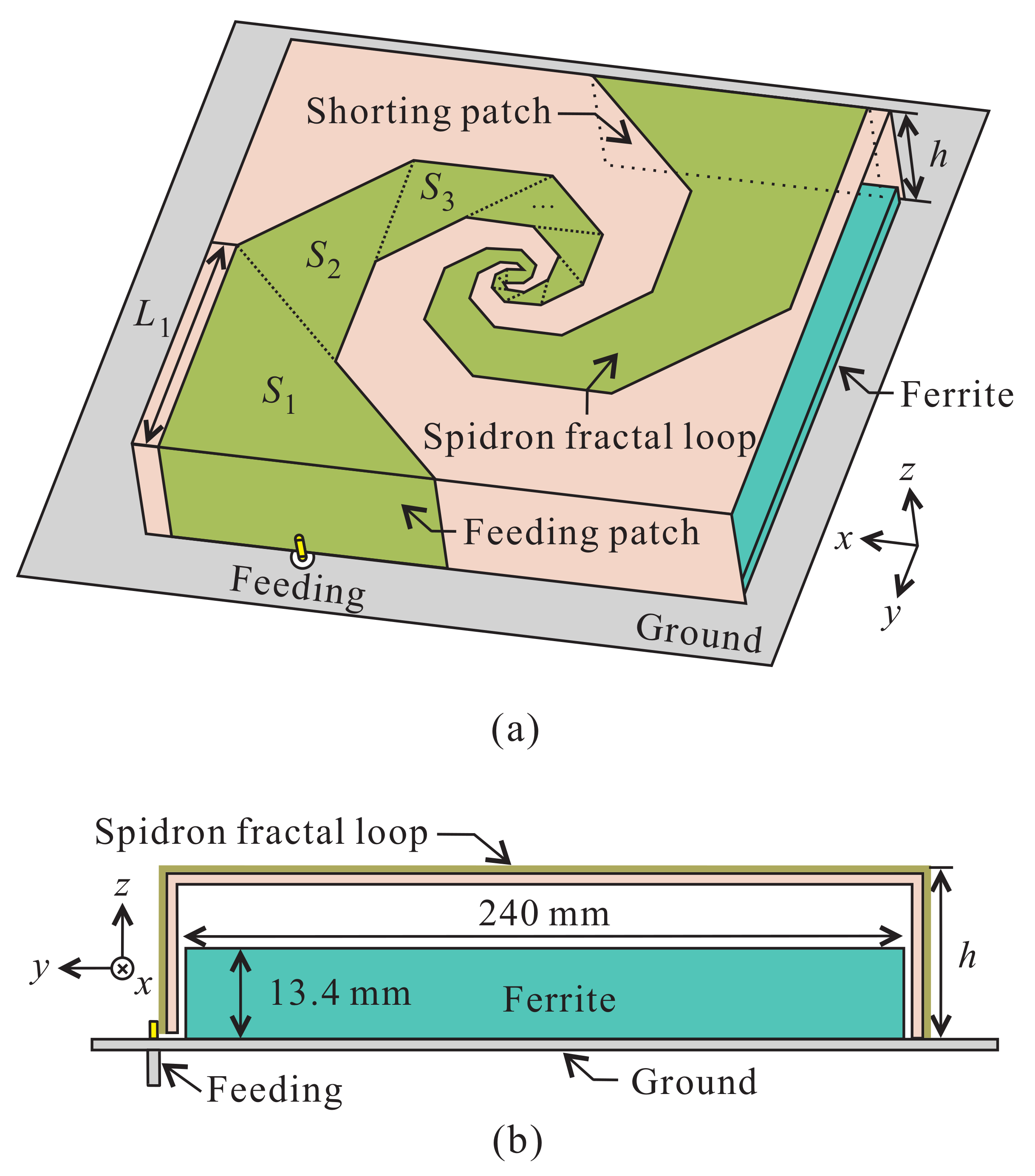
Figure 1a presents a the 3-D view of the Spidron fractal loop antenna with cuboid ferrite. The top of the loop antenna is designed with two symmetrical Spidron fractal structures which are connected to each other. A Spidron fractal is a structure in which the base of a scaled down triangle
is continuously connected to the hypotenuse of triangle
[
15]. In order to form a symmetric shape of the ferrite structure, the Spidron fractal consists of isosceles right triangles, with a down scaling factor of
. The Spidron fractal structure is attached to a shorting patch and a feeding patch. The ground plane is connected to the shorting patch and a coaxial cable is connected at the center of the feeding patch. The shorting and feeding patches are
and (
mm)
in size, respectively.
Table 1 shows the theoretical maximum gain of the electrically small loop antenna at 30 MHz. The gain is calculated according to
(the size of the antenna) [
16]. The values of
h and
are the height of the loop antenna and the length of the base of the first triangle, respectively. To ensure low-profile characteristics, the height is set to 51 mm. The length of
is set to 121 mm to achieve a theoretical maximum gain identical to the gain of a commercial antenna at 30 MHz (MT-2040/E/D, MTI Wireless Edge LTD [
17]). Because the fuselage length and wingspan of a medium-altitude long-endurance UAV are longer than 10 m on average, the size of the antenna ground plane is determined to be 10 m × 10 m. The conductor of the loop antenna structure and ground consists of copper on a Taconic RF-35 dielectric substrate with a relative dielectric constant of 3.5, a loss tangent of 0.0018, and a thickness of 1.52 mm.
Figure 1b shows the side view of the Spidron fractal loop antenna with cuboid ferrite. To increase the gain of the antenna, the ferrite structure is located inside the loop structure and attached onto the ground plane. The size of the cuboid ferrite is 240 × 240 × 13.4 mm
.
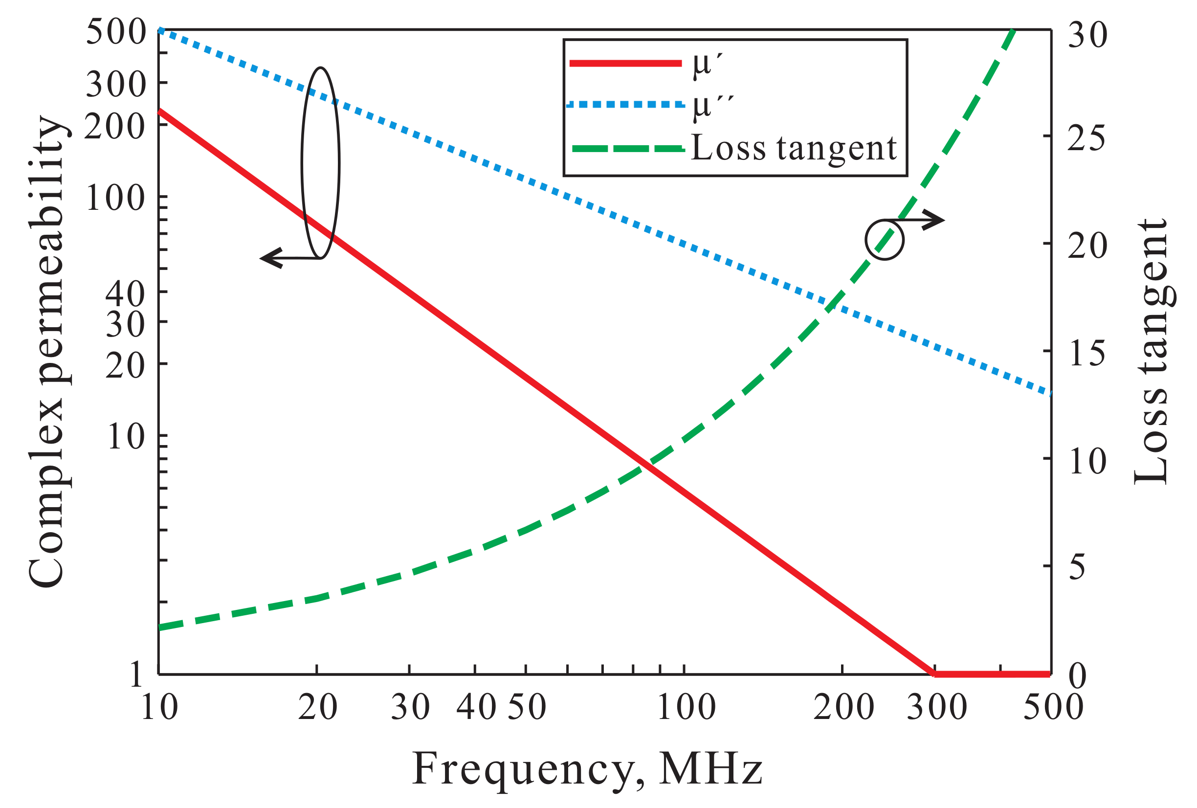
The complex permeability and magnetic loss tangent properties of the ferrite (SN-20, Samwha Electronics [
18]) are shown in
Figure 2. Here,
and
are respectively real and imaginary parts of the complex permeability, and the magnetic loss tangent of the ferrite is calculated by
. The permittivity value of the ferrite is 12 in the operating frequency band (from 30 MHz to 300 MHz). SN-20 with a high
in the HF/VHF band is very useful to improve the gain of a loop type ESA. However, the value of
gradually decreases to 1 as the frequency is increased. The magnetic loss tangent of the ferrite increases sharply as the frequency is increased because the decreasing rate of
is higher than that of
.
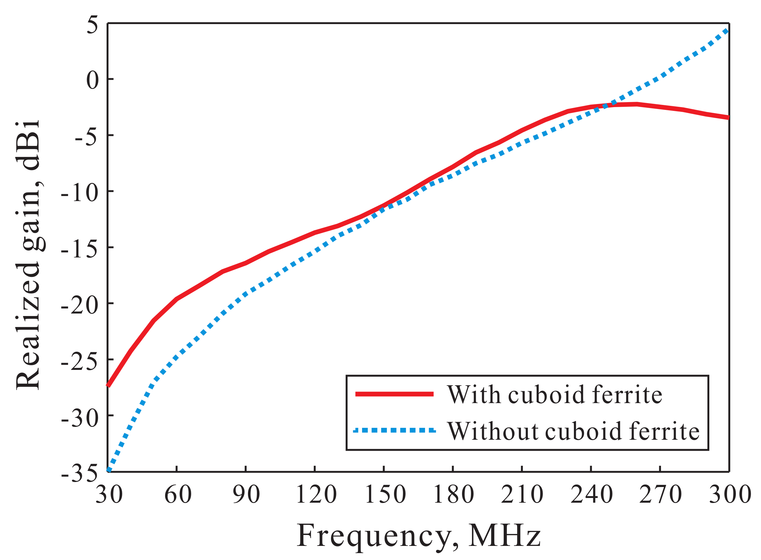
Figure 3 plots the simulated realized peak gains of the Spidron fractal loop antenna with and without cuboid ferrite. The gains of the antenna with and without ferrite range from −27.4 to −2.2 dBi and from −35.1 to 4.5 dBi, respectively, in the operating band. When the ferrite is loaded into the antenna, the radiation
Q of the antenna is reduced due to the high
of SN-20. As the result, the gain of the Spidron fractal loop antenna with the ferrite is considerably improved than that without the ferrite in the low frequency band. On the other hand, a gain reduction was noted in the high frequency band due to the high magnetic loss tangent of the ferrite.
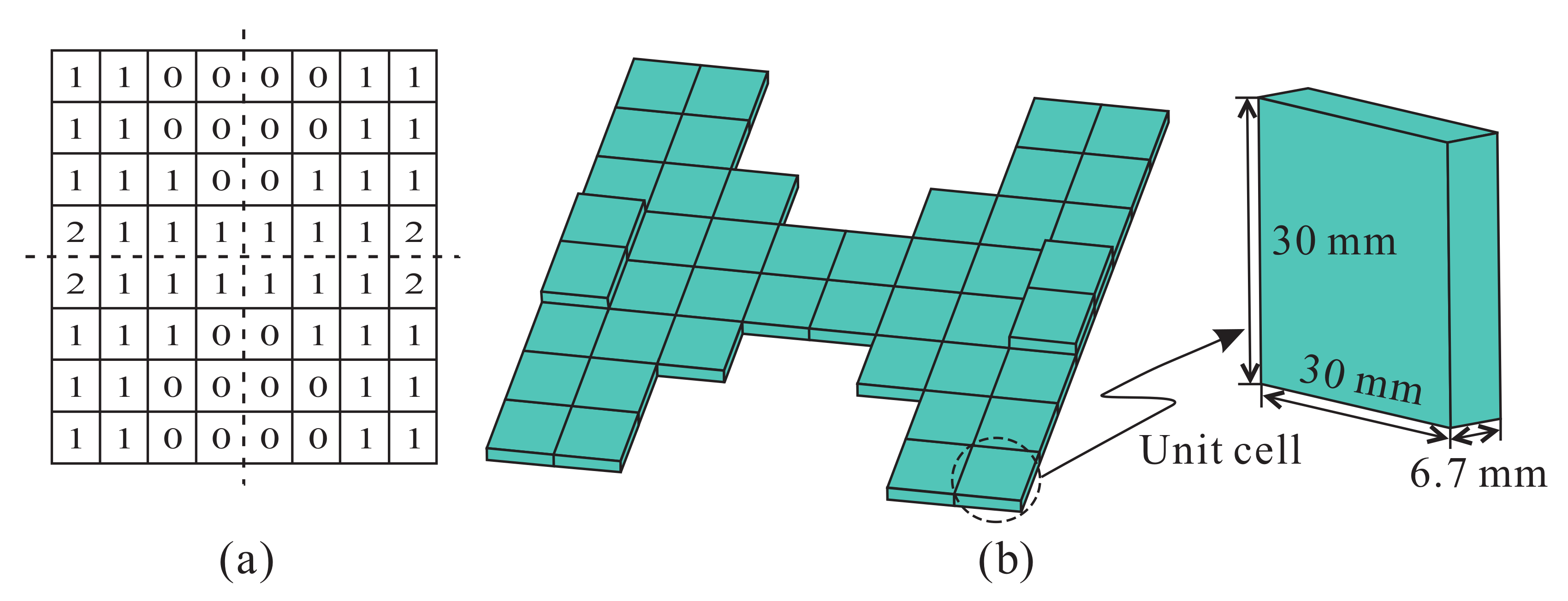
To maintain the gain improvement in the low frequency band and to solve the gain reduction problem in the high frequency band, the amount and configuration of the ferrite are optimized. The geometry of the ferrite represents an area of 240 × 240 mm
discretized into 8 × 8 grid cells. The size of a ferrite unit cell is 30 × 30 × 6.7 mm
. The 8 × 8 grid cells are divided into four quadrants, each consisting of 4 × 4 grid cells. Initially, the first quadrant is formed, followed by the second, third, and fourth, which are formed by mirroring the first quadrant in the horizontal, vertical and diagonal directions, respectively, at the center of the 8 × 8 grid cells. As a result, a symmetrical radiation pattern is obtained due to the symmetric shape of the ferrite. The 4 × 4 grid cells of the first quadrant are optimized by a GA of the type used to achieve antenna performance goals in earlier works [
19,
20]. We used MATLAB to implement the GA, and the 4 × 4 grid cells are encoded into a 16-bit ternary string with the chromosomes ‘0’, ‘1’ and ‘2’ corresponding to the number of stacked ferrite unit cells. Ternary GA optimization is conducted with MATLAB linked to CST through a CST Visual Basic script. In consideration of the payload weight limitations of UAVs, the total number of ferrite unit cells and the maximum number of chromosomes are set to 48 and 2, respectively. The optimized ternary-encoded result by the GA is given in
Figure 4a and the configuration of the optimized ferrite and unit cell is described in
Figure 4b. Through ternary genetic algorithm optimization, the ferrite is mainly formed below the conductor, where the distribution of the magnetic field is concentrated.
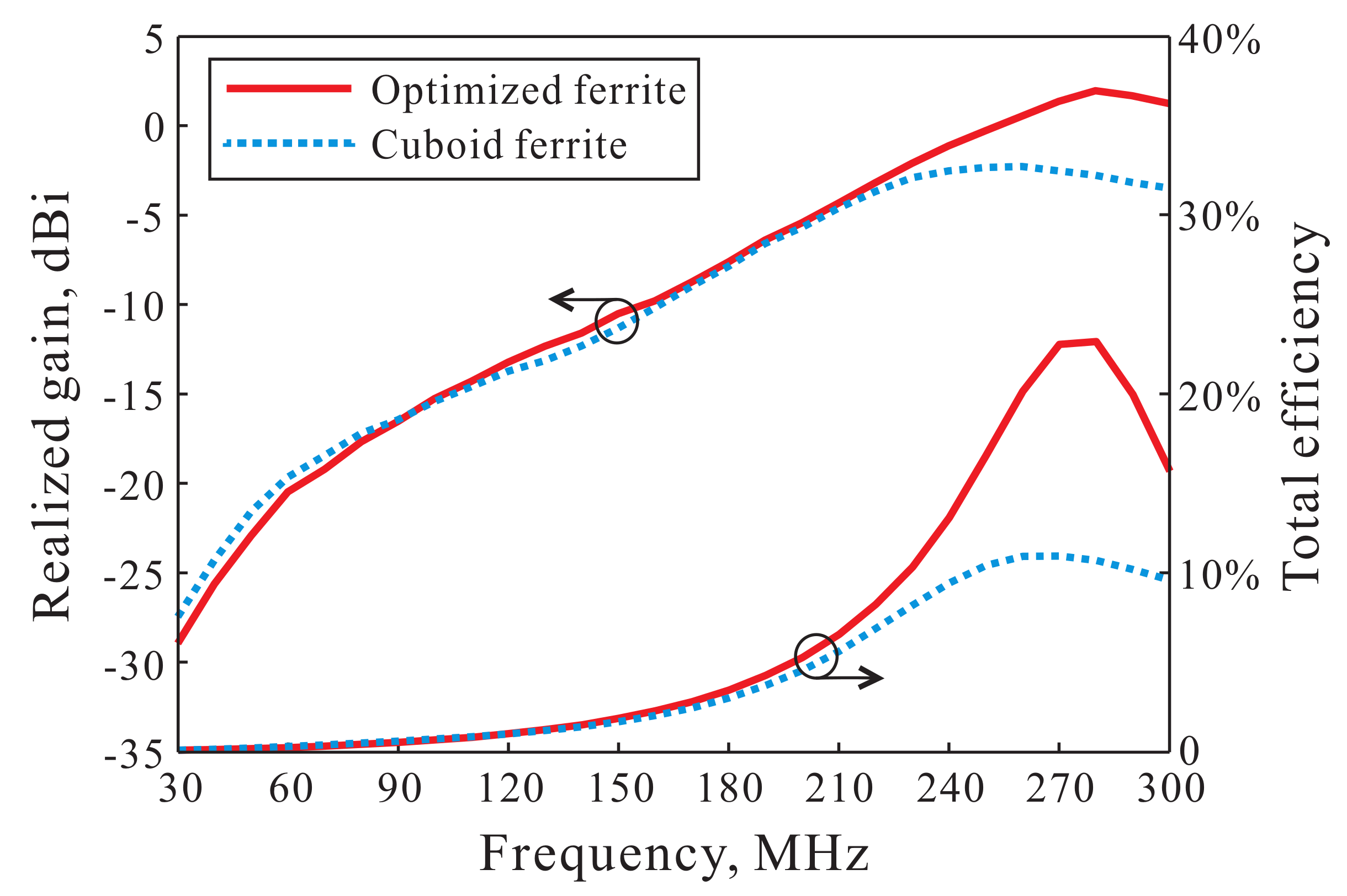
Figure 5 shows the simulated realized peak gains and the efficiency rates of the Spidron fractal loop antenna with the optimized and cuboid ferrite on the 10 m × 10 m ground plane. The configuration of the cuboid ferrite is depicted in
Figure 1b. The amount of the ferrite is decreased to 37.5% relative to the cuboid ferrite after the optimization process. The low frequency gain of the antenna with the optimized ferrite is slightly lower than that of the cuboid ferrite due to the reduced amount of ferrite. However, the gain improvement is similar to that in the results of the cuboid ferrite. In the high frequency band, the total efficiency of the antenna with the optimized ferrite is higher than that of cuboid ferrite due to the reduced magnetic loss of the ferrite. Therefore, the high frequency gain of the antenna with the optimized ferrite is improved considerably relative to that of the cuboid ferrite. The gain of the loop antenna with the optimized ferrite ranges from −28.9 to 2 dBi in the operating band.
3. Experimental Verification
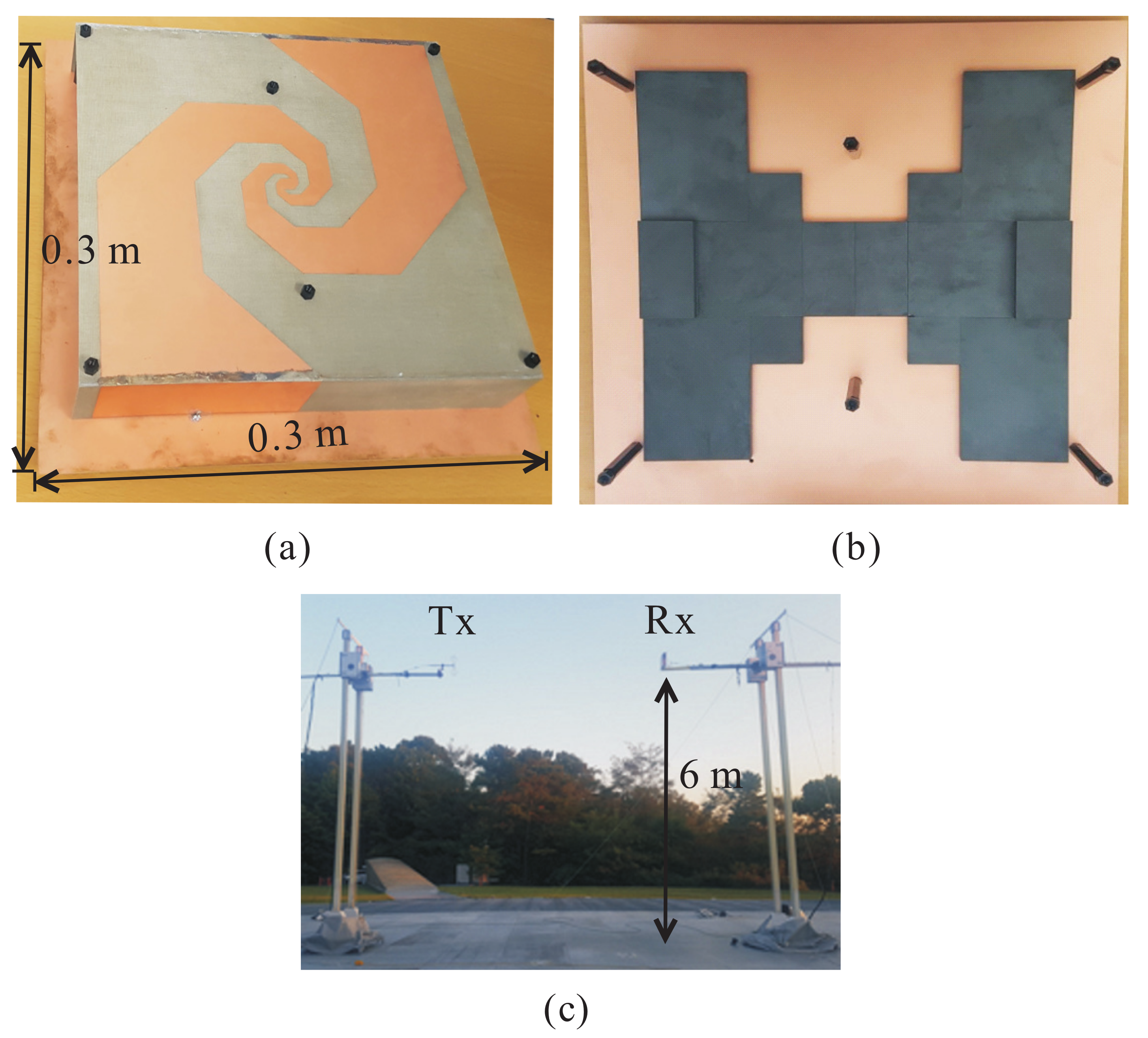
Figure 6a presents a photograph of the proposed antenna. To simplify the fabrication and measurement steps, the size of the ground plane is reduced. The ground plane of the fabricated proposed antenna has a square structure with a length of 0.3 m.
Figure 6b shows a top view of the fabricated ferrite structure. The configuration for the optimized ferrite has it is attached onto the center of the ground plane. Six nylon posts with a relative dielectric constant of 3.2 are used to support the substrate with an etched Spidron fractal structure. The antenna measurement circumstance is illustrated in
Figure 6c. The gain was measured in an electromagnetic wave open area test site 60 m × 30 m in size at the Korea Research Institute of Standards and Science. The transmission and receiving antenna (proposed antenna) is positioned 6 m above the ground.
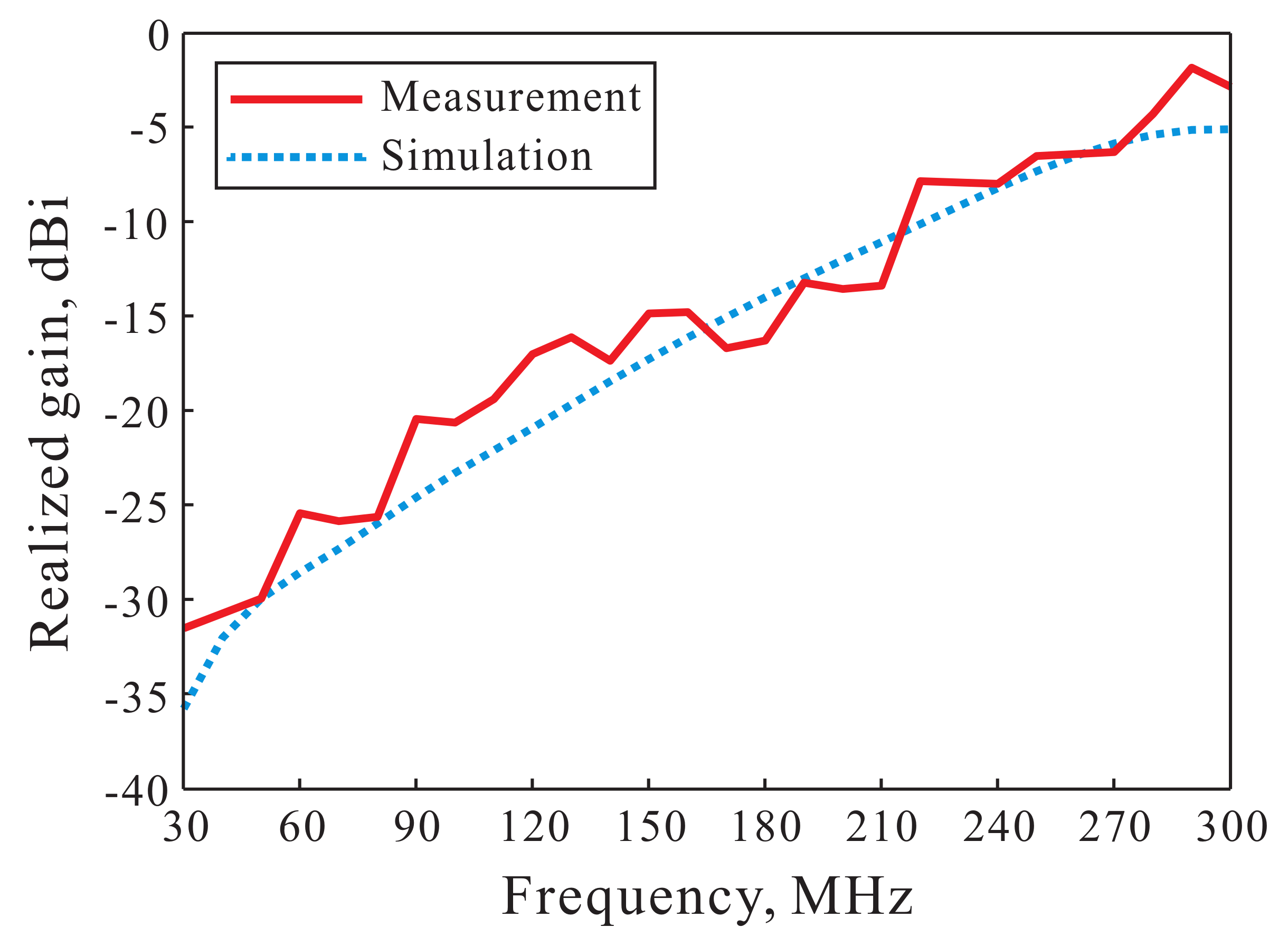
Figure 7 presents the simulated and measured realized peak gains of the proposed antenna on the
-plane. The realized peak gains are the total radiated power of the linear polarization. The simulated and measured gains range from −35.8 to −5.1 dBi and from −31.6 to −1.9 dBi, respectively. This graph indicates that the simulated and measured results are in good agreement in the operating frequency band. The slight difference between the simulated and measured results arose due to calibration differences and reflected and scattered waves from the ground.
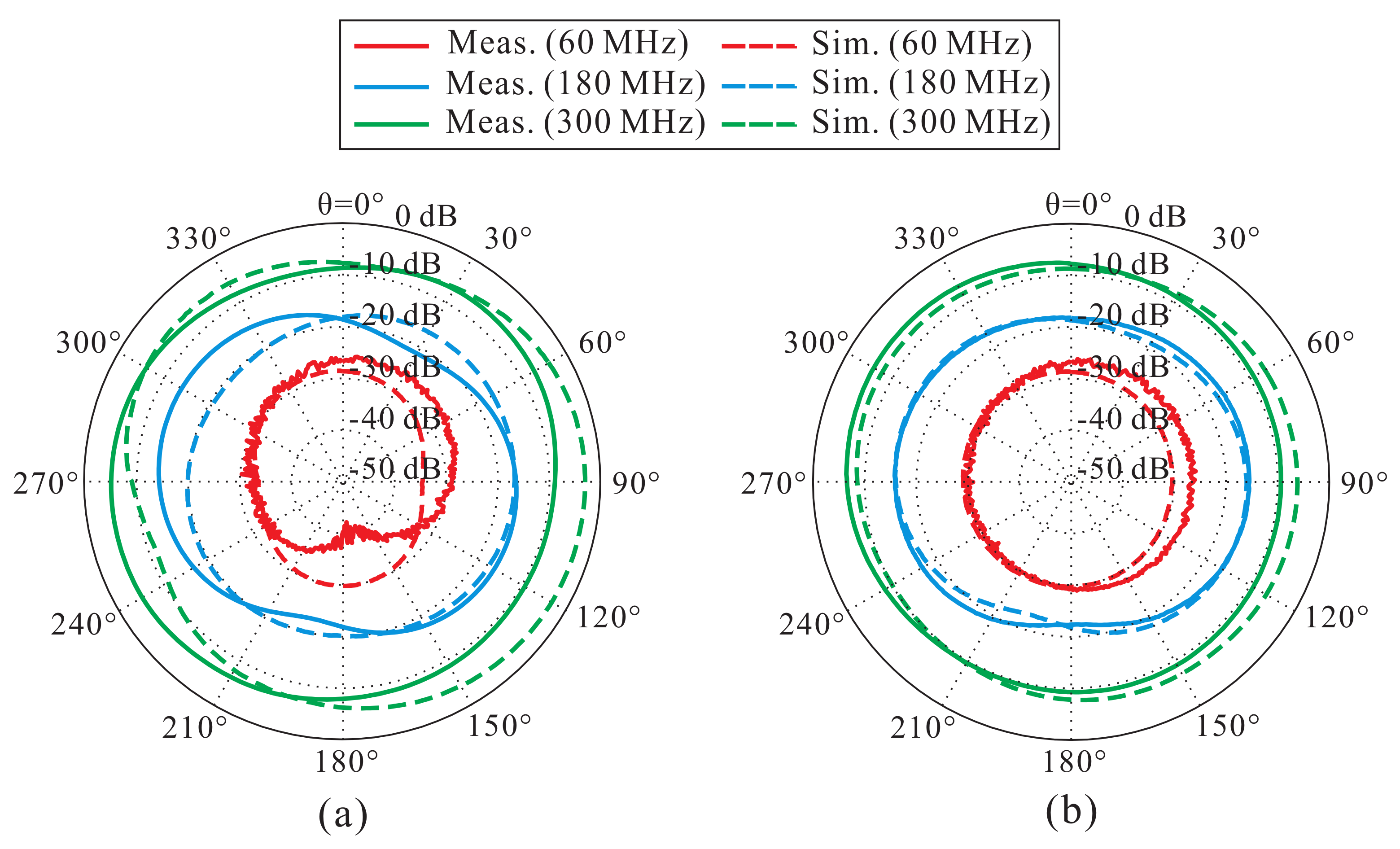
Simulated and measured radiation patterns at 60, 180, 300 MHz on two planes (
-plane and
-plane) are shown in
Figure 8. The simulated and measured results are indicated by the dashed and solid lines, respectively. The radiation patterns of the proposed antenna are omni-directional at all frequencies. The feeding location is tilted toward the
-axis relative to the center of the antenna, resulting in some asymmetry patterns. The differences between the simulated and measured results arose due to the weather at the measurement center, manufacturing uncertainties, and similar causes.
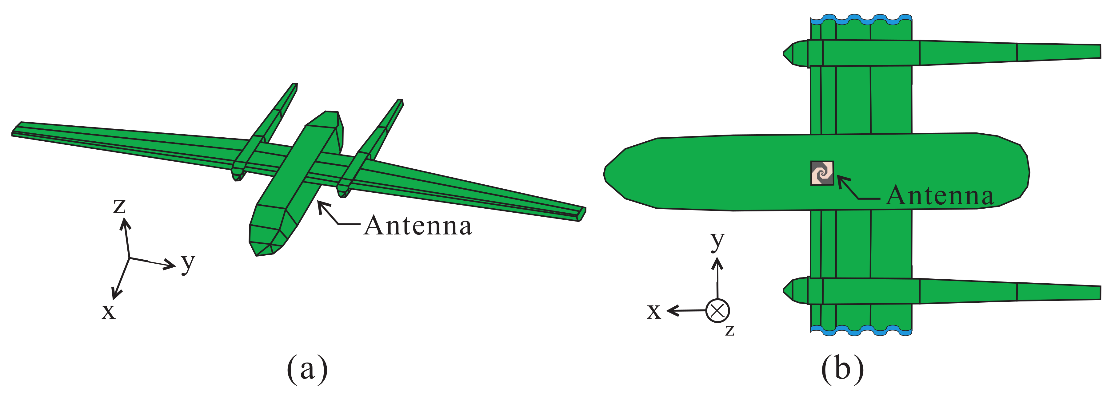
Figure 9a,b show a 3-D view and bottom view of the UAV model, respectively. The shape of the UAV is modeled to examine the performance of the proposed antenna mounted on the UAV. The UAV model consists of a fuselage and wings, and all surfaces are implemented as conductors. The size of the UAV model is similar to the size of a typical UAV. The proposed antenna is mounted on the bottom of the fuselage of the UAV and faces the—
z-axis.
Figure 10 presents the simulated realized peak gains of the proposed antenna on a UAV and on flat ground. Flat ground here is defined as the proposed antenna on a square ground plane with the area denoted by round brackets. On flat ground, the simulated gains for the (0.3 m × 0.3 m) case are approximately 5 dBi lower than that for the (10 m × 10 m) case in the operating frequency band owing to the ground size. By mounting the proposed antenna on the UAV, the overall structure of the UAV becomes the ground of the antenna. The gain characteristics on the UAV are similar to those on flat ground (10 m × 10 m) because the ground size of the antenna on the UAV is sufficiently large. Therefore, flat ground (10 m × 10 m) can be used instead of a UAV model. The realized gains of the proposed antenna on UAV range from −23.9 to −0.6 dBi. The slight discrepancies in the gain of the antenna on the UAV and flat ground (10 m × 10 m) are caused by the antenna directivity, which is affected by the UAV structure.
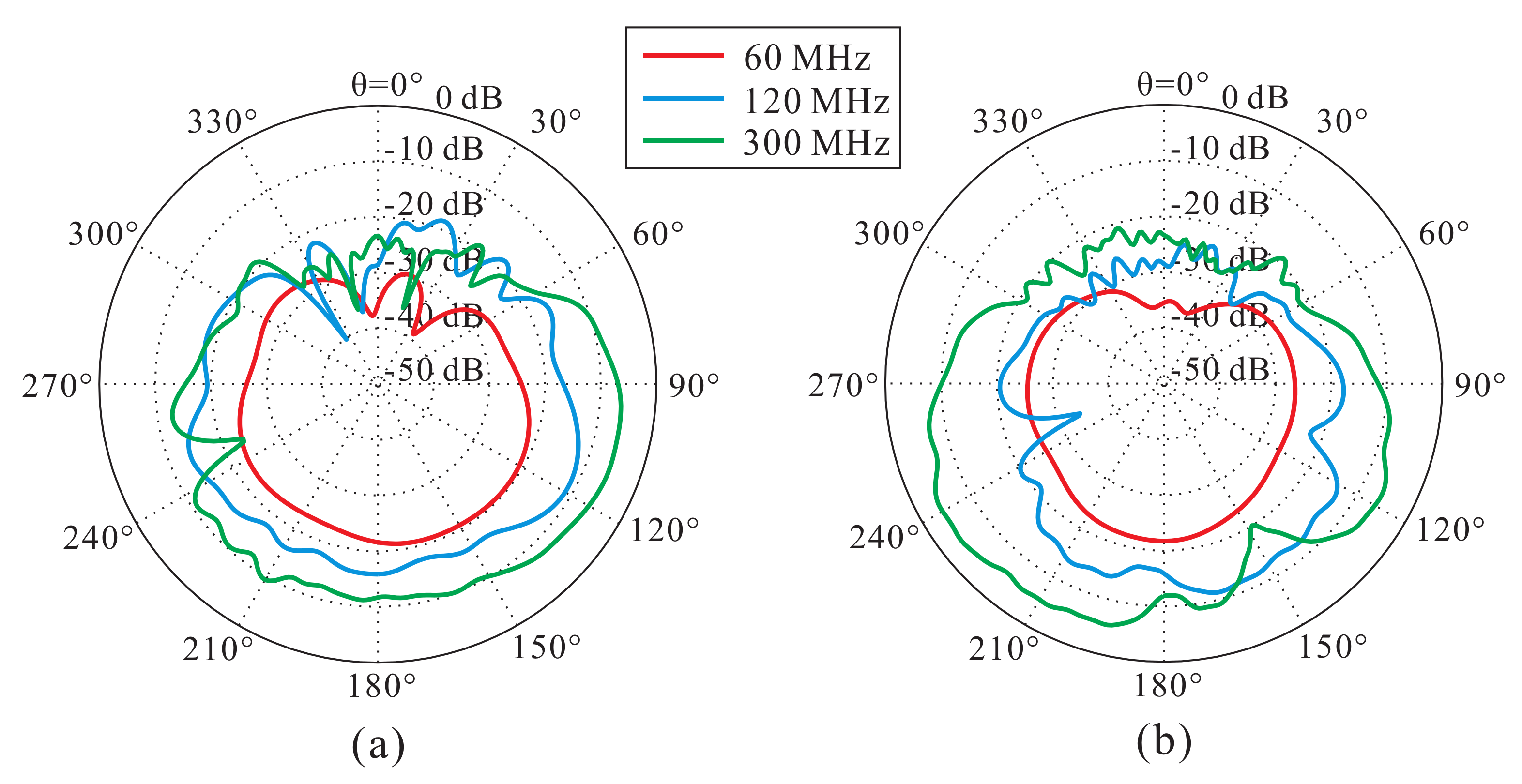
Simulated far-field radiation patterns of the proposed antenna mounted on the UAV on two planes (
-plane and
-plane) are depicted in
Figure 11. This figure shows that radiation patterns are influenced less by the UAV structure at 60 MHz due to the longer wavelength. However, when the frequency is higher, the patterns are influenced more by the UAV structure. The
-plane and
-plane patterns are asymmetric and different from each other due to the shape of the fuselage, the wings of the UAV, and the feeding location. The pattern in the downward direction (90
270
) is directional and can receive communication signals at all downward directions.


