Article

Research and Improvement of the Hydraulic Suspension System for a Heavy Hydraulic Transport Vehicle

1
Hebei Provincial Key Laboratory of Heavy Machinery Fluid Power Transmission and Control, Yanshan University, Qinhuangdao 066004, China
2
College of Mechanical Engineering, Anhui Technical College of Mechanical and Electrical Engineering, Wuhu 241000, China
3
Key Laboratory of Advanced Forging & Stamping Technology and Science, Yanshan University, Qinhuangdao 066004, China
4
Hebei Key Laboratory of Special Delivery Equipment, Yanshan University, Qinhuangdao 066004, China
5
State Key Laboratory of Fluid Power and Mechatronic Systems, Zhejiang University, Hangzhou 310027, China
6
Tianjin Key Laboratory of Aerospace Intelligent Equipment Technology, Tianjin Institute of Aerospace Mechanical and Electrical Equipment, Tianjin 300458, China
*
Author to whom correspondence should be addressed.
Appl. Sci. 2020, 10(15), 5220; https://doi.org/10.3390/app10155220
Submission received: 1 July 2020 / Revised: 20 July 2020 / Accepted: 27 July 2020 / Published: 29 July 2020
(This article belongs to the Section Mechanical Engineering)

Abstract

:

Featured Application

Adding an accumulator in a suspension system can effectively reduce the hydraulic impact caused by an uneven road, and the appropriate accumulator parameters can be obtained through combined simulation.

Abstract

In order to ensure the ride comfort of a hydraulic transport vehicle in transportation, it is important to account for the effects of the suspension system. In this paper, an improved hydraulic suspension system based on a reasonable setting of the accumulator was proposed for a heavy hydraulic transport vehicle. The hydraulic transport vehicle was a multi-degree nonlinear system, and the establishment of an appropriate vehicle dynamical model was the basis for the improvement of the hydraulic suspension system. The hydraulic suspension system was analyzed, and a mathematical model of the hydraulic suspension system with accumulator established and then analyzed. The results revealed that installing the appropriate accumulator can absorb the impact pressure on the vehicle, while a hydraulic suspension system with an accumulator can be designed. Further, it was proved that a reasonable setting for the accumulator can reduce the impact force on the transport vehicle through simulation, and the optimal accumulator parameters can be obtained. Finally, an experiment in the field was set up and carried out, and the experimental results presented to prove the viability of the proposed method.

1. Introduction

The suspension system is one of the most important components of a transport vehicle, which can improve the ride comfort, running stability, and reduce the impact force caused by an uneven road. Therefore, it is very important to select the suspension design scheme and suspension parameters in a reasonable way. The large impact force on the vehicle load-bearing platform will aggravate the up and down vibration of the tire, affect the adhesion between the wheel and the ground, and affect the braking force, which will cause a great impact on the stability of the vehicle [1,2,3]. The hydraulic suspension system has great advantages, one of the main functions is to reduce the impact on the vehicle load-bearing platform. The hydraulic suspension system has been used for a long time, and it can not only improve the ride comfort of the vehicle, but also realize raising and lowering of the body. The transportation requirements are ride comfort, stability, and safety but because of the poor compressibility of hydraulic oil, the rigidity of the hydraulic suspension is substantial and the absorption of the impact force is poor. Through simulation analysis, Banerjee, S. improved the vibration reduction of a vehicle and optimized the parameters of the hydro-pneumatic suspension [4]. Choi, S.B. realized vibration control through a synovial control strategy [5]. Francois. compared different gas models to calculate the spring force of a hydro-pneumatic suspension and found that the hydro-pneumatic suspension model on considering energy conversion was more accurate [6]. Wang, G.Y. improved the ride comfort of a vehicle by changing the damping of the suspension under different working conditions [7]. Through simulation, Ansari, F.A. obtained the best parameters for accumulator pressure for a heavy trailer suspension [8]. Zhang, S.Z. obtained a calculation method for the suspension accumulator according to the limiting working condition [9]. Zhao, J.Y. studied the compliance of self-adaption suspension group systems in self-propelled transporters [10]. Liu, X. proposed an observer-based active fault-tolerant controller for a vehicle suspension system [11]. Gui, Z. analyzed the effects of an uneven road on a multi-axle vehicle with hydraulic suspension and found that increasing the axle number of the multi-axle vehicle can effectively suppress the dynamic load on the frame and suspension [12].
The heavy hydraulic transport vehicle studied is shown in Figure 1. It is a special transport vehicle, not a conventional road vehicle. It is mainly used for transportation in construction sites.
Based on the previous work, an improved method for a hydraulic suspension system is proposed in this paper. First, the structure of the suspension system was analyzed and expressed by a mathematical model. The main function of the accumulators in a hydraulic suspension system of a transport vehicle is to absorb the impact pressure, so the diaphragm type accumulator was selected. The hydraulic suspension system with accumulators was designed, then the mathematical model of the accumulator and the dynamic model of the vehicle established. Finally, the combined simulation was realized by ADAMS and AMESim, and the optimal parameters of the accumulator obtained. The experiment was compared with the simulation, which verified the correctness of the simulation and design.

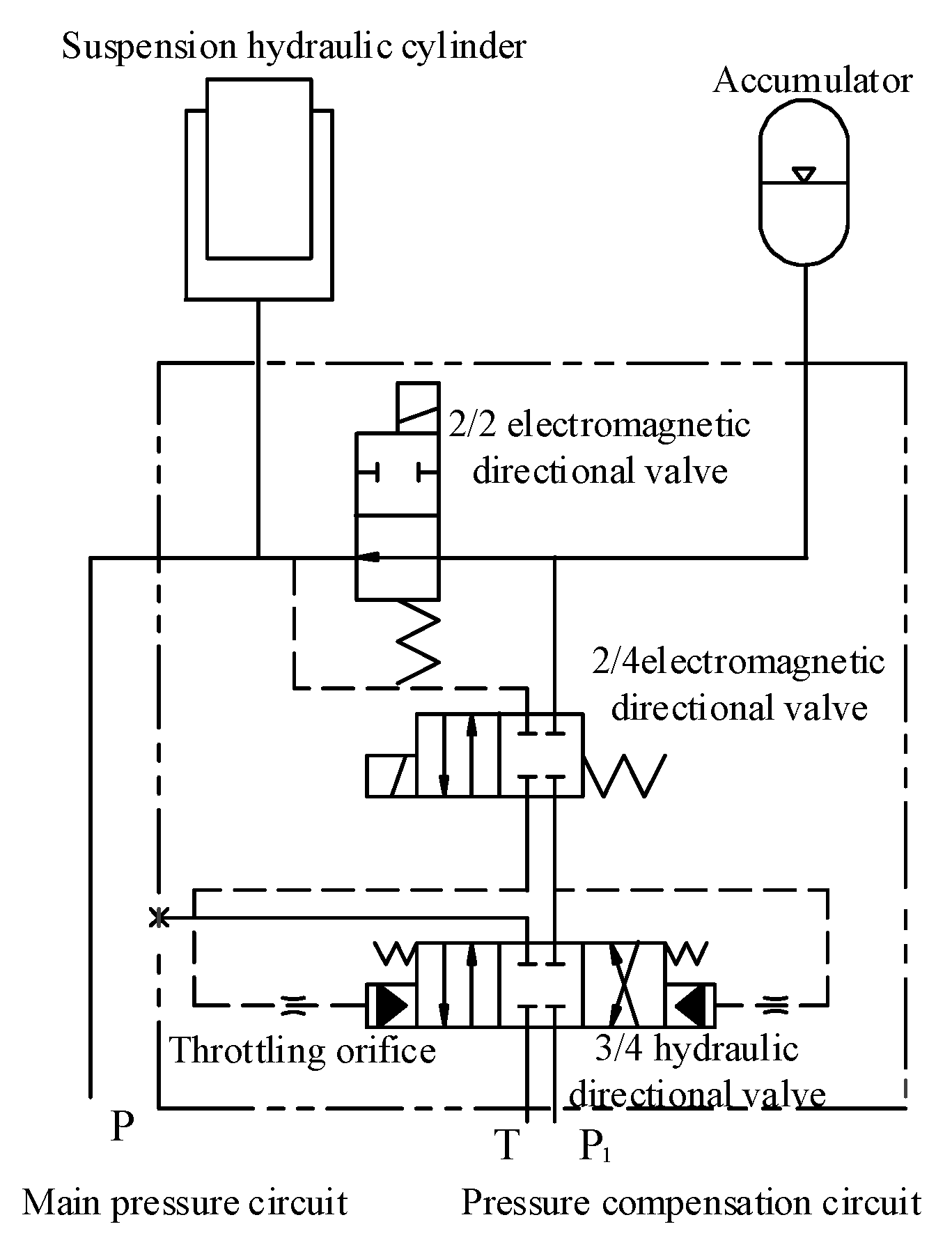
2. Analysis of the Suspension System

The suspension system is the key component of the hydraulic transport vehicle. Its main function is to support the vehicle load-bearing platform and buffer the load. It can also control the lifting action of the whole vehicle [13]. Therefore, the suspension system is very important as it affects the stability of the vehicle. Each axis of a hydraulic transport vehicle is equipped with two sets of hydraulic suspension systems, each set of which is separately connected with the frame through a rotary support. The composition of the hydraulic suspension system is shown in Figure 2.
The single hydraulic suspension system can be simplified into a mechanism as shown in Figure 3.
The initial angle between the suspension frame and the suspension balance arm is a. It is assumed the rotation angle of the suspension balance arm relative to the suspension frame is c, and the stroke of the corresponding suspension cylinder is x. The following equation can be obtained.
L A C + x = L 2 A B + L 2 B C 2 L A B L B C cos ( a + c )
According to the moment balance equation of the suspension mechanism, Equation (2) is obtained as follows.
F L 1 = G L 2
where F is the force of the suspension cylinder, G is the load on each suspension.
According to the triangle area equation, Equation (3) can be obtained.
1 2 L A B L B C sin ( a + c b ) = 1 2 ( L A C + x ) L 1
So L1 and L2 can be obtained as follows.
L 1 = L A B L B C sin ( a + c b ) L 2 A B + L 2 B C 2 L A B L B C cos ( a + c b )
L 2 = L B D cos ( a + c j )
So, Equation (2) can be transformed as follows, which is the relationship between the force on each suspension and the force of one suspension cylinder.
F L A B L B C sin ( a + c b ) L 2 A B + L 2 B C 2 L A B L B C cos ( a + c b ) = G L B D cos ( a + c b )
The full load G on each hydraulic suspension is 17 t, the force F of the suspension cylinder is related to the geometric parameters of the suspension structure, and it can be obtained from Equation (6). The force is 382.52 N and the working pressure of each suspension hydraulic cylinder is 21.3 MPa when the vehicle is fully loaded. When the transport vehicle is running on an uneven road, it can be adjusted freely by the telescopic movement of the suspension cylinders, so that the load-bearing platform is always in a horizontal state, but there will be a hydraulic impact on the suspension cylinder.
The main reason for hydraulic impact is that the kinetic energy of the hydraulic oil is converted into pressure energy instantaneously. According to the law of conservation of energy, the dynamic energy of hydraulic oil is converted into elastic potential energy, Equation (7) can be obtained as follows:
1 2 ρ V v 2 = 1 2 V K Δ P 2
where V is the volume of the hydraulic oil, v is the average flow velocity, ρ is density of the hydraulic oil, K’ is the equivalent bulk modulus of the hydraulic oil, ΔP is the impact pressure.
So, the impact pressure can be obtained as follows:
Δ P = ρ K ρ v = ρ c v
where c is the transmission velocity of the pressure shock wave in the pipeline.
According to the above theory, two simple hydraulic cylinders can be selected as approximate suspension hydraulic cylinders for analysis. There are multiple suspension hydraulic cylinders in the hydraulic transport vehicle similar to this. The two states of the two hydraulic cylinders are shown in Figure 4.
The two hydraulic cylinders are the same. In the initial position, the two cylinders are in the same horizontal position and the pressure value is the same. It is assumed that the oil is incompressible. According to the change of oil volume in the two cylinders, the following equations can be obtained.
V 1 + V 2 = 2 V 0
V 2 V 1 = π ( d 2 ) 2 Y
where V0 is the initial oil volume of the two cylinders, V1 is the oil volume of the left cylinder after change, V2 is the oil volume of the right cylinder after change, ΔV is the changed oil volume, d is the diameter of the cylinder, Y is the change of road surface.
According to Equations (9) and (10), ΔV can be obtained as follows.
Δ V = V 2 V 0 = π d 2 8 Y
According to the relationship between volume and flow, the changed oil flow Q can be obtained from Equation (12) while the average flow velocity can be obtained as Equation (13).
Q = d Δ V d t = π d 2 8 d Y d t
v = Q π ( d 2 ) 2 = 1 2 d Y d t
The relationship between the average flow velocity and the road unevenness is shown as Equation (13). However, it is a simplified model, in practice, there is a certain angle between the position of the suspension cylinder and the vertical direction, which should be further considered in an accurate calculation. According to Equation (13), Equation (8) can be transformed as follows.
Δ P = 1 2 ρ c d Y d t
From Equation (14), it can be seen that the impact pressure is mainly related to the change of the road surface and the time used. Because the type of hydraulic oil and pipeline has been selected and the unevenness of the road cannot be changed, improving the stability of the transport vehicle can only be achieved by lowering the speed of the vehicle and setting the accumulator. The main function of the accumulator in the suspension system is the gas spring. During transportation, the compression and release of gas can absorb well the impact pressure of the suspension cylinder caused by the uneven road surface and impact load.

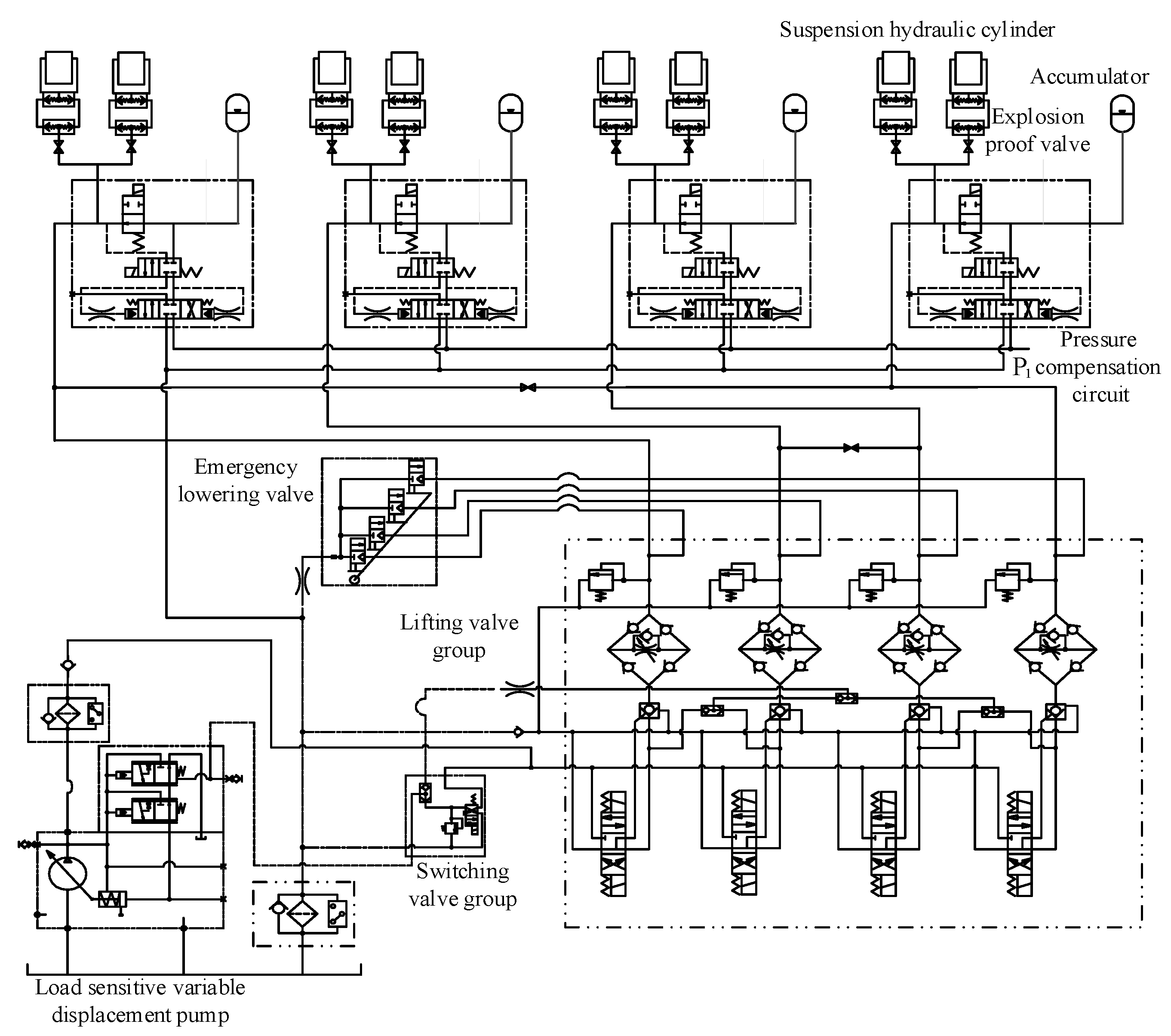
3. Improvement of the Suspension Hydraulic System

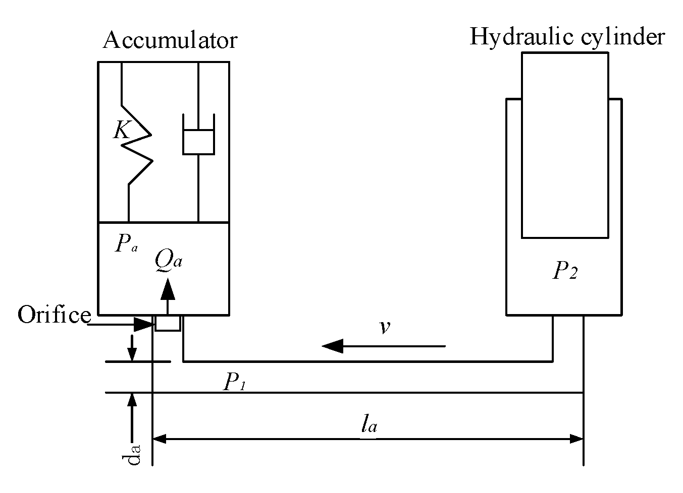
3.1. Accumulator Setting

The accumulator is an important elastic element in the suspension system of the transport vehicle, so the accumulator selected was the diaphragm type accumulator. When the transport vehicle is running, the accumulator and the hydraulic cylinder can form a hydraulic spring suspension, which can be used to absorb the impact and vibration transmitted by the road. When the transporter is lifting and lowering, the load will change and the motion will be out of sync. This is due to the poor load resistance of the accumulator. In order to solve this problem, the suspension hydraulic system with accumulator was designed as shown in Figure 5. It is composed of a three- position four-way hydraulic directional control valve, a two-position four-way electromagnetic directional control valve, a two-position two-way electromagnetic directional control valve, and throttling orifices.
When the transport vehicle is ready to lift, the two-position two-way electromagnetic reversing control valve is electrified to change the direction and cut off the accumulator from the hydraulic system. At the same time, the two-position four-way electromagnetic directional control valve is electrified, and the two hydraulic control ports of the hydraulic directional control valve are respectively connected with the hydraulic cylinder and the accumulator to realize the pressure compensation to the hydraulic cylinder. After the lifting operation is completed, the all directional control valves return to the initial state, and the accumulator can be reconnected into the system without impact. Because the pressures in the accumulator and the hydraulic cylinder are always equal, connection without impact of the accumulator can be realized.

3.2. The Improved Hydraulic System of Suspension

The schematic diagram of the suspension hydraulic system of the transport vehicle after adding the accumulators is shown in Figure 6. The load sensing technology was adopted in the hydraulic system. The output flow and system pressure of the pump can be changed with the demand of the load and maintains a good flow with pressure matching. The multi-way valve can maintain a good proportional characteristic, which can reduce the power loss of the system. The inlet and outlet pressure of the proportional multi-way valve can be kept constant, so that the output flow of the proportional multi-way valve cannot be affected by the load.

4. Modeling and Simulation

With the wide application of the hydraulic transport vehicle in transportation, the requirements on ride comfort are becoming higher and higher, to ensure the safety of the transportation. In order to verify that the accumulator can reduce the impact on the vehicle, and for the optimal parameter selection of the accumulator, a simulation of the vehicle with the accumulators was carried out.

4.1. Mathematical Model Analysis of Accumulator

When the accumulator is connected to the system, it is generally connected through a section of pipeline, which has a great influence on the characteristics of the accumulator. Therefore, when modeling the accumulator, the connecting pipeline can be considered as a part of the accumulator. In practical application, the connecting pipeline between the accumulator and the suspension cylinder should be as short as possible. The accumulator system diagram is shown as Figure 7.
In addition, the following assumptions should be made when modeling the accumulator [14,15]. The charge pressure of the accumulator is a slow process, so the change of gas pressure and volume can be seen as an isothermal process; the discharging process of the accumulator is fast, and the gas does not exchange heat with the outside world, so it can be considered as an adiabatic process approximately; the compressibility of hydraulic oil is quite different from gas, so it can be ignored; and the flow of hydraulic oil in the accumulator can be regarded as laminar flow. The approximate flow continuity equation of the accumulator can be expressed as follows.
Q a = C d A d 2 ρ Δ P
where Qα is the flow into accumulator, Cd is the orifice discharge coefficient, Ad is the orifice area, and ΔP’ is the pressure difference before and after the orifice.
The motion equation of the hydraulic oil in the connecting pipeline and the accumulator is as follows.
L d Q a d t + R Q a = P 1 P a
where L is the liquid inductance, R is the fluid resistance, P1 is the pressure of the pipeline.
L and R are expressed as follows.
L = ρ l a A d
R = 128 μ l a π d a 2
where μ is the kinetic viscosity, la is the length of the pipeline between accumulator and hydraulic cylinder, da is the diameter of the pipeline.
The main function of the accumulator is to absorb the impact pressure of the system. The type of gas charged in the accumulator is nitrogen. The required volume of the accumulator can be calculated according to the Equation (19).
V a = 0.004 Q P 2 ( 0.0164 l a t ) P 2 P 1
where Va is the required volume of the accumulator, Q is the flow in the pipeline, P2 is the maximum allowable impact pressure, t is the time from the beginning to the end of impact. After calculation and analysis, the accumulator (075-1315-042-711) of Integral Corporation is selected. As the air spring, the accumulator absorbs the impact pressure, and its spring stiffness K is equal to the ratio of the force ΔF exerted by the volume change of accumulator gas on the suspension cylinder to the displacement Δx of the cylinder. It is shown as follows.
K = Δ F Δ x = Δ P A Δ V / A = A 2 d P d V = A 2 k P a V 2 a k V 1 a k + 1
where ΔV’ is the changed volume of the gas in the accumulator, V1a is the gas volume in the initial state, V2a is the gas volume in the impact state, A is the area of the cylinder, k is the isentropic exponent of the gas, Pa is the pressure of the accumulator at any moment.

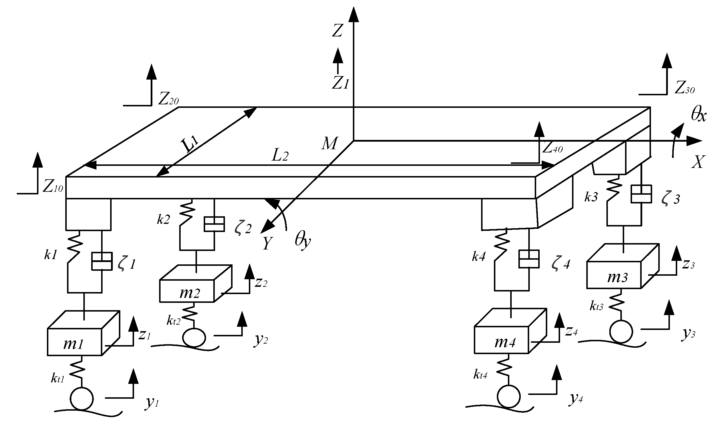
4.2. Motion Equation of the Vehicle

The transport vehicle is a complex multi-body system, which has not only an interaction force and relative displacement between the components, but also an interaction between the tire and the road. Therefore, it is very difficult to establish an accurate dynamic model of the whole vehicle. According to the structure of the transport vehicle studied, the following assumptions can be made when building a vehicle motion model [16].
The compressibility of the liquid can be considered as a spring, and the throttle effect of the valve and the leakage of the hydraulic cylinder can be considered as damping. The elasticity of the frame, the load-bearing platform, and the driver’s cab is much less than that of the suspension system, and they are regarded as rigid bodies without considering elastic deformation. The vibration influence of the diesel engine, transmission shaft, and gearbox on the whole vehicle is ignored. Because only the suspension system of the vehicle is studied, the influence of the steering system is not considered. The center of gravity of goods is assumed to remain unchanged under full load condition.
The simplified dynamic model of the vehicle is modeled as shown in Figure 8, and M is the mass of the vehicle load-bearing platform, mi is the mass of wheel, ki is the stiffness of the hydraulic suspension, kti is the stiffness of the tire, ζi is the damping of the hydraulic suspension, zi0 is the vertical displacement of the connection point, zi is the vertical displacement of the tire center, yi is the unevenness of the road, Z1 is the vertical displacement of the mass center, θx, and θy is the angle of rotation around the X-axis and Y-axis.
According to Newton’s law and the dynamic model of the vehicle, the force and vertical displacement of the connection point can be obtained as follows [17].
F i = k i [ z i z i 0 ] + c i [ z ˙ i z ˙ i 0 ] ( i = 1 , 2 , 3 , 4 )
{ z 10 = Z 1 0.5 L 1 θ x 0.5 L 2 θ y z 20 = Z 1 + 0.5 L 1 θ x 0.5 L 2 θ y z 30 = Z 1 0.5 L 1 θ x + 0.5 L 2 θ y z 40 = Z 1 + 0.5 L 1 θ x + 0.5 L 2 θ y
According to Equations (21) and (22), the three direction motion equations of the vehicle load- bearing platform can be obtained as Equation (23). The motion equation of the unsprung mass is obtained as Equation (24).
{ M Z ¨ 1 = F i I X θ ¨ x = 0.5 [ ( F 2 + F 4 ) ( F 1 + F 3 ) ] L 1 I Y θ ¨ y = 0.5 [ ( F 3 + F 4 ) ( F 1 + F 2 ) ] L 2
m i z ¨ i + ζ i ( z i z i 0 ) + k i ( z i z i 0 ) + k t i ( z i y i ) = 0 ( i = 1 , 2 , 3 , 4 )
where IX is the rotation inertia of the platform about the X-axis, IY is the rotation inertia of the platform about the Y-axis.
The vibration equation of the whole system can be obtained as follows.
[ M ] Z ¨ + [ ζ ] Z ˙ + [ K ] Z = [ K t ] Y
where M is the mass matrix, ζ is the damping matrix, K is the stiffness matrix, Kt is the tire stiffness matrix, Q is the unevenness matrix of the road.

4.3. The Simulation Model

Because hydraulic transport vehicles are used to transport heavy goods, the class B road is selected in the simulation, a 3D road is established with a length of 10 m and a width of 3 m. The tire is also an important part of the vehicle, so the accuracy of the tire model plays an important role in the characteristics of the transport vehicle model. The suspension system of the whole vehicle is studied, not only the vertical force of the tire, but also the longitudinal force and external force should be considered, so the UA tire type is selected [18]. According to the tire type and specific parameters of the transport vehicle, a tire model is obtained. This hydraulic transport vehicle is self-propelled, so the wheels are added to drive directly in the model. The final vehicle model is established as shown in Figure 9.
Then the AMESim model of the suspension system is built. And the ADAMS model is imported into the AMESim model, the combined simulation model can be obtained as shown in Figure 10. The parameters of the model are set according to the design. The sampling interval is set as 0.01 s in ADAMS, and in order to observe the simulation process clearly, the sampling period is set as 0.001 s in AMESim [19]. In the simulation, an impact load 104 N is added to the vehicle load-bearing platform at the 10th second.

4.4. The Parameter Selection of the Accumulator

The initial charging pressure of the accumulator is 30 bar in the simulation, the pressure fluctuation curves of one suspension hydraulic cylinder are obtained by taking different accumulator volumes, as shown in Figure 11. It can be seen that the fluctuations of cylinder pressure are relatively small in the first 3 s, because the system is not stable when it is first started. After 5 s, it can be seen that the pressure fluctuation of the cylinder is relatively small when the accumulator volume is 0.75 L, and the fluctuation range is within 5 bar. The pressure fluctuations are relatively large under other volumes, which obviously cannot meet the requirements. Therefore, the accumulator volume is selected as 0.75 L.
After the accumulator volume is set to 0.75 L, the pressure fluctuation curves of the suspension hydraulic cylinder are obtained under the different accumulator charging pressures, as shown in Figure 12. It can be seen that the pressure fluctuation of the cylinder is at a minimum when the charging pressure is 30 bar. Under other charging pressures, the pressure fluctuations of the suspension hydraulic cylinder are too large to meet the requirements. Therefore, the charging pressure of the accumulator is selected as 30 bar.

5. Analysis of the Experiment and Simulation

When the vehicle is running with full load, the ride comfort standard of this special transport vehicle is such that the impact pressure of the suspension hydraulic cylinder is no more than 20 bar, and the height change of the vehicle platform should be less than 50 mm [20,21,22].
From the above simulation results, it can be concluded that the accumulator setting plays a positive role in suspension impact reduction. In order to verify the simulation results, the experiment in the field was carried out as shown in Figure 13.
The data acquisition in the experiment is based on LabVIEW software. The principle of data transmission is shown in Figure 14. The data of sensors can be converted into voltage signals, and the corresponding pressure value can be obtained after conversion and calculation. Data measuring in the field experiment is shown in Figure 15.

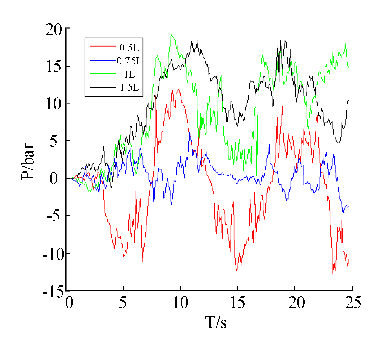
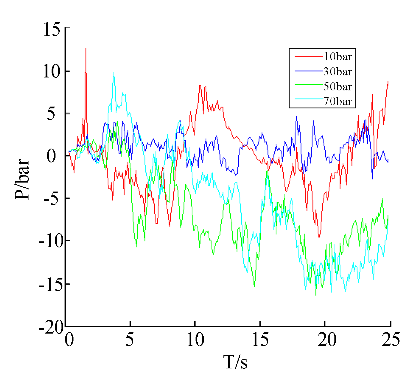
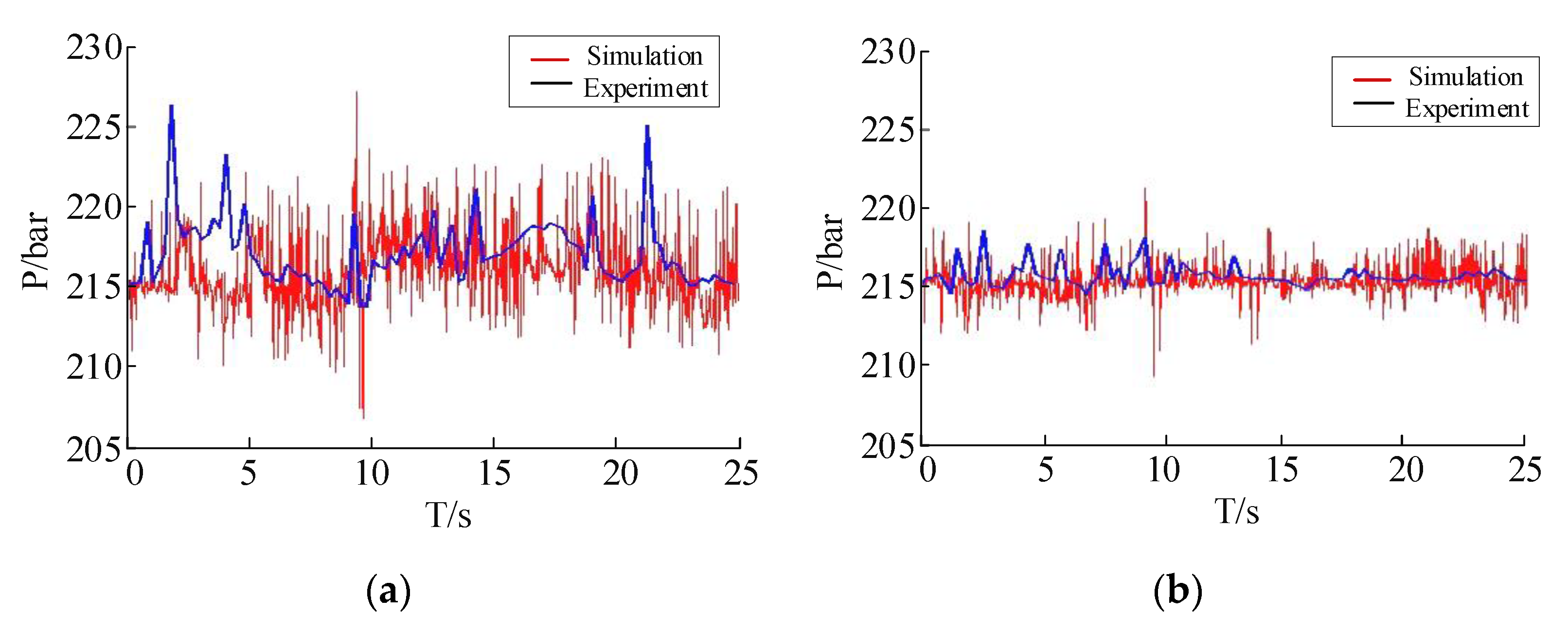
5.1. Pressure of the Suspension Cylinder

In the experiment, the cement blocks are selected as the load, and the speed is set to 10 km/h. The pressure curves of one suspension cylinder are obtained and compared with the combined simulation as shown in Figure 16. It can be seen that the input impact load causes the impact pressure at the 10th second. When the accumulator is connected, the impact pressure is obviously reduced, and the maximum reduction is 12 bar. From Figure 16, it can be seen that the pressure fluctuation of the suspension hydraulic cylinder is large when the accumulator is disconnected, the maximum and minimum pressure are 227 bar and 207 bar in the experiment; but when the accumulator is connected, the pressure fluctuates within 7 bar, and the fluctuation is relatively smooth. The experimental results are basically consistent with the combined simulation results, which shows the correctness of the simulation, and further verifies the rationality of the accumulator parameter selection.

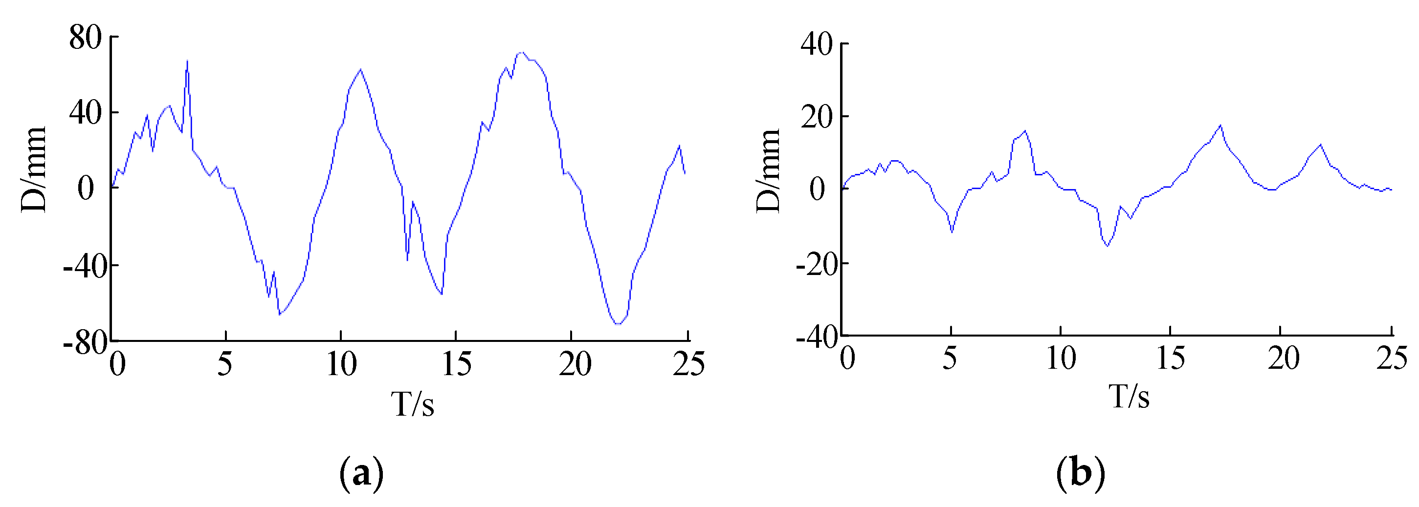
5.2. Ride Comfort of the Vehicle

In order to verify the correctness of the design, the change curves of the vehicle load-bearing platform center are collected as shown in Figure 17. When the accumulator is on, it can be seen that the height of the vehicle platform changes smoothly, and the displacement change of the vehicle platform in the vertical direction is obviously reduced.

6. Conclusions

The suspension system of a newly developed hydraulic transport vehicle was studied in this paper. The suspension system of the transport vehicle was analyzed in detail, and the impact force on the transport vehicle caused by the uneven road analyzed and calculated. Based on the analysis of the accumulator mathematical model and the whole vehicle motion equation, the 3D model including the road and vehicle were created, and the model imported into AMESim model, and finally a combined simulation carried out. The simulation results show that a reasonable selection of accumulator parameters can reduce the impact pressure of the suspension cylinder. Finally, a real vehicle field experiment was carried out, and the data of one suspension hydraulic cylinder with the accumulator on and off under full load collected when the vehicle was running at normal speed. The research results show that the setting of the accumulator and a reasonable selection of parameters not only have a great effect on the impact pressure reduction of the suspension cylinder, but also have a positive effect on the ride comfort of the transport vehicle.

Author Contributions

J.Z. proposed the research method. The simulation and experiments were performed and the manuscript was written by W.L. and J.W. The creation of models and the manuscript revision were performed by X.J. and P.W. All authors have read and agreed to the published version of the manuscript.

Funding

This research was funded by the National Key Research and Development Program of China (2019YFB2005204), National Natural Science Foundation of China (51675461, 11673040), Key Research and Development Program of Hebei Province (19273708D), the Scientific Research Project Foundation of Anhui Education Department (KJ2019A1161), the Open Foundation of the State Key Laboratory of Fluid Power and Mechatronic Systems (GZKF-201922) and the Open Project Program of Tianjin Key Laboratory of Aerospace Intelligent Equipment Technology, Tianjin Institute of Aerospace Mechanical and Electrical Equipment.

Conflicts of Interest

The authors declare no conflict of interest.

References

  1. Wu, B.G.; Li, S.P.; Yan, S.F. Vehicle Ride Comfort Simulation Based on Virtual Prototyping Technology. Appl. Mech. Mater. 2014, 697, 190–193. [Google Scholar] [CrossRef]
  2. Chen, Y.K.; He, J.; King, M.; Feng, Z.X.; Zhang, W.H. Comparison of two suspension control strategies for multi-axle heavy truck. J. Cent. South Univ. 2013, 20, 550–562. [Google Scholar] [CrossRef] [Green Version]
  3. Jiang, H.; Wang, B.; Huang, J. Suspension Parameters Optimization Based on Ride Comfort and Road Friendliness of Truck. Mod. Transp. Technol. 2008, 5, 71–74. [Google Scholar]
  4. Banerjee, S.; Balamurugan, V.; Krishnakumar, R. Ride dynamics mathematical model for a single station representation of tracked vehicle. J. Terramech. 2014, 53, 47–58. [Google Scholar] [CrossRef]
  5. Choi, S.B.; Han, Y.M. Vibration control of electrorheological seat suspension with human-body model using sliding mode control. J. Sound Vib. 2007, 303, 391–404. [Google Scholar] [CrossRef]
  6. van der Westhuizen, S.F.; Els, P.S. Comparison of different gas models to calculate the spring force of a hydropneumatic suspension. J. Terramech. 2015, 57, 41–59. [Google Scholar] [CrossRef] [Green Version]
  7. Wang, G.Y.; Li, X.L.; Zhang, Y. Scheme Design of Hydro-pneumatic Spring Type Variable Damping for Some Mining Vehicle. J. Acad. Armored Force Eng. 2013, 27, 46–50. [Google Scholar]
  8. Ansari, F.A.; Ranjan, R.; Korade, D.N.; Jagtap, K.R. Characterizationof Hydraulic Suspension System, on The Basis of Accumulator Pressure Values for a Special Purpose Vehicle. Mater. Today Proc. 2017, 4, 709–716. [Google Scholar] [CrossRef]
  9. Zhang, S.Z.; Chen, J.Y.; He, L. Calculation Method of the Suspension Accumulator According to the Limiting Working Condition. Hydraul. Pneum. Seals 2019, 4, 19–25. [Google Scholar]
  10. Zhao, J.Y.; Kang, S.P.; Cheng, F.; Fan, L.Z. Compliance of Self-adaption Suspension Group Systems in Selfpropelled Transporters. Chin. Mech. Eng. 2016, 27, 3103–3110. [Google Scholar]
  11. Liu, X.; Pang, H.; Shang, Y. An Observer-Based Active Fault Tolerant Controller for Vehicle Suspension System. Appl. Sci. 2018, 8, 2568. [Google Scholar] [CrossRef] [Green Version]
  12. Gui, Z.; Han, F.; Zhang, H.S. An Analysis on the Effects of Road Roughness on Multi-Axle Vehicle with Hydraulic Suspension. Automob. Eng. 2010, 32, 155–158. [Google Scholar]
  13. Zhao, J.Y.; Cheng, F.; Guo, R.; Dai, J.J. Research on Electro-hydraulic Synchronization Driving Control for Self-Propelled Transporter Suspension Lifting. Chin. Mech. Eng. 2014, 7, 972–978. [Google Scholar]
  14. Dong, M.; Luan, X.T.; Liang, J.L.; Wu, B.Y. Dynamic Characteristics Analysis of Absorbing Pulsation for Bladder Accumulator. Chin. Hydraul. Pneum. 2019, 5, 109–116. [Google Scholar]
  15. Zhen, J.R.; Shi, W. AMESim Simulation of Accumulator Having Effection of Synchronous Cylinder. Hydraul. Pneum. Seals 2012, 5, 10–13. [Google Scholar]
  16. Wei, J.H.; Du, H.; Fang, X.; Guo, K. Road-Friendliness of Interconnected Hydro-Pneumatic Suspension Based on ADAMS/Simulink/AMESim. Trans. Chin. Soc. Agric. Mach. 2010, 41, 11–17. [Google Scholar]
  17. Peng, Y.Q. Study on Vehicle Dynamics Modeling and Optimization of Key Parameters Based on Ride Comfort. Master’s Thesis, Guangdong University of Technology, Guangzhou, China, 2015. [Google Scholar]
  18. Wu, C.; Wang, W.R.; Chen, Y. Simulation and validation of three-dimensional road surface spectrum. J. Zhejiang Univ. (Eng. Sci.) 2009, 43, 1935–1938. [Google Scholar]
  19. Huang, X.J.; Cao, Y.W.; Li, S.F. Simulation Analysis on Dynamic Loads of Heavy-Duty Semitrailer Model Based on ADAMS. J. Chongqing Jiaotong Univ. (Nat. Sci.) 2012, 31, 128–132. [Google Scholar]
  20. Pang, H.; Li, H.Y.; Fang, Z.D.; Wang, J.F. Stiffness Matching and Ride Comfort Optimization of Heavy Vehicle’s Suspension Based on ADAMS. Appl. Mech. Mater. 2010, 44–47, 1734–1738. [Google Scholar] [CrossRef]
  21. Zhou, K. Study of Heavy Transport Vehicles Side Leveling Control System. Spec. Purp. Veh. 2007, 11, 39–41. [Google Scholar]
  22. Zhao, J.Y.; Yang, Y.J.; Kang, S.P.; Wang, Z.J.; Liu, T.T. Research and application of four-point support “flat chasing style” leveling strategy on self-propelled hydraulic transporter. Mach. Tool Hydraul. 2015, 43, 57–60. [Google Scholar]
Figure 1. The hydraulic transport vehicle.
Applsci 10 05220 g001
Figure 2. Schematic diagram of the suspension system.
Applsci 10 05220 g002
Figure 3. The simplified mechanism.
Applsci 10 05220 g003
Figure 4. (a) The initial state; (b) the state of encountering an uneven road.
Applsci 10 05220 g004
Figure 5. The schematic diagram of the accumulator setting.
Applsci 10 05220 g005
Figure 6. The schematic diagram of the improved suspension hydraulic system.
Applsci 10 05220 g006
Figure 7. The accumulator system diagram.
Applsci 10 05220 g007
Figure 8. The dynamic model of the vehicle.
Applsci 10 05220 g008
Figure 9. The model of the whole vehicle.
Applsci 10 05220 g009
Figure 10. The combined simulation model.
Applsci 10 05220 g010
Figure 11. The pressure fluctuations of the cylinder under different volumes of accumulator.
Applsci 10 05220 g011
Figure 12. The pressure fluctuations of the cylinder under different charging pressures of the accumulator.
Applsci 10 05220 g012
Figure 13. The experiment in the field.
Applsci 10 05220 g013
Figure 14. The principle of data transmission and acquisition.
Applsci 10 05220 g014
Figure 15. Data measuring in the field.
Applsci 10 05220 g015
Figure 16. The pressure of one cylinder: (a) Accumulator off; (b) accumulator on.
Applsci 10 05220 g016
Figure 17. The platform height change: (a) Accumulator off; (b) accumulator on.
Applsci 10 05220 g017

