Article

Design and Construction of a Low-Cost Test Bench for Testing Agricultural Spray Nozzles

Department of Agriculture, Food and Environment (Di3A), Section of Mechanics and Mechanization, University of Catania, via Santa Sofia, 100, 95123 Catania, Italy
*
Author to whom correspondence should be addressed.
Appl. Sci. 2020, 10(15), 5221; https://doi.org/10.3390/app10155221
Submission received: 3 July 2020 / Revised: 22 July 2020 / Accepted: 27 July 2020 / Published: 29 July 2020
(This article belongs to the Special Issue Pesticide Applications in Agricultural Systems)

Abstract

:

Featured Application

A low-cost test bench to evaluate spray quality of agricultural nozzles was designed and built. The system allows for testing nozzles under effective work conditions at different pressure and flow rate values.

Abstract

Droplet size distribution is probably the most important feature of a spray as it affects all aspects of a phytosanitary treatment, i.e., biological, environmental, and safety aspects. This study describes a low-cost laboratory test bench able to analyze agricultural spray nozzles under realistic conditions. The design of the equipment was mainly based on the ISO 5682-1 standard. It has a couple of 3 m long rails, along which the nozzle under test moves while spraying, controlled by a closed-loop position and speed controller. The drops were captured with three Petri dishes containing silicone oil, photographed by means of a digital single-lens reflex (DSLR) camera, and then analyzed with the ImageJ software in order to measure the usual spray parameters: the volumetric diameters, the Sauter mean diameter, and the number mean diameter. Spray trials and tuning of the system parameters were managed by means of a purposely designed user interface running on a Windows 10 PC. Some tests were carried out by using an Albuz ATR80 orange hollow cone nozzle at the working pressures of 0.3, 0.5, 1.0, and 1.5 MPa. The results about spray quality agree with the factory information, and the whole system, even if some aspects still need improvements, has proven reliable.

1. Introduction

Spraying plant protection products (PPPs) is recognized as one of the agricultural activities most impacting on human health and the environment, also at the regulatory level [1]. Effects of PPPs on human health involve operators, farm workers and bystanders, consumers, professionals, and the general population, whereas those on the environment involve water, soil and atmosphere quality, and nontarget organisms such as vertebrates, useful arthropods, and other invertebrates. Therefore, on one hand researchers and manufacturers operate to get PPP application more sustainable according to the precision agriculture principles and on the other to promote nonchemical approaches.
Precision agriculture requires treating huge amount of data coming from several sources and sensors [2,3,4,5,6,7], from which to obtain prescription maps to be used with innovative spraying systems [8,9,10,11,12,13,14,15,16]. In addition, approaches for a more reasonable and sustainable use of PPPs include integrated pest management and organic farm [1,17,18,19,20,21,22,23], which allow for a reduction in the amount of chemical pesticides used.
Worker’s exposure and environmental effects of pesticides are affected by various variables, among which include active substances, adjuvants, formulation, type of equipment used and its status, task being performed, target features, canopy structure, amount of pesticide handled, packaging, environmental conditions, duration of activity, personal protective equipment used, and others. A key factor is the spray spectrum, evaluated in terms of droplet size distribution [24,25,26,27,28,29], because an optimal droplet spectrum ensures the transfer of the required dose to the target, minimizes the off-target losses due to evaporation, drift, and run-off, and reduces dermal and inhalation worker exposure [30,31,32,33,34,35,36,37].
According to Schick [38], drops can be sampled for measurement purposes via spatial or flux techniques, and both methods affect the results. Spatial technique presupposes sampling instantaneously a number of drops occupying a given volume, whereas flux technique presupposes the examination of individual drops passing during an interval of time through the cross-section of a sampling region. The first method is sensitive to the number of particles in each class size and per unit volume, whereas the second to the particle flux.
Drop size analyzers available on the market that implement the spatial sampling technique include the optical imaging (OI) and the laser diffraction (LD) analyzers. Both systems are nonintrusive and do not influence the spray behavior during the measurement. The flux sampling technique is implemented by optical array probes (OAPs) and phase doppler particle analyzers (PDPAs). Both systems are nonintrusive also, are single particle counters, and allow for measuring drop size and velocity contemporarily.
Other methods, both intrusive and nonintrusive, are based on digital image analysis (DIA). Nonintrusive methods include the acquisition and analysis of the spray jet image [39], high-speed imaging [40], and shadowgraphy [41]. Among intrusive methods based on DIA, the use of water sensitive papers (WSPs) is probably the most diffused [42,43,44,45,46,47,48,49]. WSPs are artificial targets with a yellow surface layer that turns blue when in contact with water. This property allows for registering the droplet stains in spray tests. Assuming as known the spread factor (ratio between stain diameter and drop diameter) and negligible the overlap between stains, stain image analysis allows for determining the droplet size distribution.
A different approach, intrusive too, is to trap the droplets inside a layer of silicone oil of suitable density and viscosity and then analyze their image. The method is adopted by ISO 5682-1 [50], and it is exploited in this study to design and construct a low-cost test bench useful for evaluating agricultural spray nozzles.
The main aim of the paper is to provide a comprehensive description of the test bench (a preliminary study was presented in [51]), namely its design, construction, advantages, and limitations during its functioning. In addition, to test the functionality of the whole system, the results of some trials with an ATR80 orange hollow cone nozzle are reported.

2. Materials and Methods

2.1. Test Bench Design Guidelines

The test bench, applied on a movable trolley, was designed and built at the Section of Mechanics and Mechanization of the Di3A (University of Catania, Catania, Italy) based on the ISO 5682-1 standard, dealing with Equipment for crop protection–Spraying equipment–Test methods for sprayer nozzles. In addition, two main aspects were taken into consideration: the low cost of the whole equipment and test conditions similar to those present in standard commercial sprayers. With respect to the first aspect, the cost of mechanical structure and hardware components was less than 5000 €, whereas the cost of the image acquisition system (a camera with a macro lens that can also be used independently for other applications) was about 1200 €. Globally, the cost of the whole equipment was much lower than that of PDPA systems, though these systems allow for measuring drop velocity also. With regard to the second aspect, the test bench allows for testing agricultural spray nozzles under ordinary work conditions in a 1:1 scale for water flux, pressure, nozzle speed, and distance from the target.
According to the ISO 5682-1 reference, the nozzle under test should move above a row of Petri dishes with equal surface areas, spraying a test liquid (clean water with the addition of a soluble coloring agent, free from solids in suspension). Each Petri dish receives some of the droplets from the jet. All the droplets in each Petri dish should be measured and classified by size so that the cumulative volumetric curves and all the usual distribution parameters can be calculated. The accuracy of the equipment in measuring the drop diameter should be within 10 µm.
The selected nozzle speed should allow for a sufficient number of droplets to be collected (at least 2000 droplets should be collected to make a representative sample), while avoiding the merging of the droplets. The maximum speed fixed by the ISO 5682-1 standard is 3 m/s. The distance between the nozzle and Petri dishes should correspond to the normal distance between the nozzles and the crop. Finally, the test has to be carried out by letting the spraying nozzle pass once over the row of Petri dishes.
Other solutions, such as those described by Ali et al. [52], were discarded because they are based on the use of water sensitive papers. Calculation of spray spectrum parameters by using water sensitive papers (WSPs) requires knowledge of the spread factor as well as the overlap between stains to be made negligible. The spread factor is reported in WSP data sheets, but it is calculated at well-defined conditions (water temperature 20 °C, relative humidity 40%, droplets reaching the WSP at sedimentary velocity), which are different from real conditions and thus greater errors are expected.

2.2. Hydraulic Component Design

According to the aims of the research, the design of the hydraulic circuit was carried out in a way that is very similar to the standard spraying system installed on commercial sprayers. For this reason, a 70-liter plastic tank and a diaphragm pump (AR 30, Annovi Reverberi, Reggio Emilia, Italy, able to ensure pressure values up to at least 3 MPa) were chosen. The pump is driven by a single phase 230 V AC, 2.2 kW induction motor with a gearbox. As the pump capacity is much higher than the flow rate of the nozzle under test, the surplus was recirculated to the main tank by means of a pressure regulator as it is in the sprayers to ensure continuous mixing of the liquid.
In addition, to take into account the different working pressure ranges of the nozzles under test, the circuit was designed with two pressure lines (Figure 1): a low (up to 0.6 MPa) and a high pressure line (up to 3 MPa). According to the needs, the required working pressure was established by manually selecting the proper line by acting on the appropriate ball valves and then by acting on the corresponding pressure regulator.
Due to the effect of the spray pressure and nozzle flow rate on the drop pulverization, the design of the hydraulic circuit also provided the sensors to measure in real time both quantities. Fluid pressure at the nozzle was measured by means of a piezoresistive pressure transmitter (Series 22 S model from Keller Italy Srl, Milano, Italy) and flow rate by means of a turbine flow sensor (SF800-6 model from Swissflow BV-Fazantlaan 4 6026 SN Maarheeze, The Netherlands). The pressure transmitter (3.0 MPa full-scale) has a standard 4–20 mA analog output, while the flow sensor has a digital pulse output with a nominal coefficient of 6000 pulse/L, a flow rate limit between 0.5 and 20 L/min, and a maximum operating pressure of 25 MPa.

2.3. Mechanical Component Design

The design of the mechanical components of the test bench took into consideration the following main aspects:
  • possibility to control speed and position of the nozzle under test while spraying;
  • mechanical insulation of the Petri dishes containing the drops from the pump and motors to avoid the transmission of vibration;
  • general safety aspects due to the movement of the nozzle.
The movement of the nozzle under test was achieved by anchoring it to a mobile platform supported by four wheels and translating it along two rails mounted on the trolley by means of four steel supports (Figure 2). The mobile platform carries one triple nozzle holder, and the nozzle under test was manually selected. The platform was pulled by two parallel toothed belts (one at each side of the platform) of SynchroBeltTM type, by means of a 250 W, 24 V DC permanent magnets (PMDC) brushed motor with a 6.75:1 gearbox. The rails, 3 m long, were spaced 0.6 m apart from each other, and were placed above and parallel to the trolley plane, at a distance of 0.6 m.
The motion of the mobile platform is closed-loop controlled by means of a motor control unit (MDC1460 model, Roboteq Inc., Scottsdale, AZ, USA). The acceleration, speed, and position are controlled by means of a 300 ppr (pulse per revolution) rotary quadrature optical encoder (ME22 model, INTECNO srl), directly applied to the main shaft of the PMDC motor. A simple symmetric trapezoidal speed shape was chosen, with the platform moving at constant speed while spraying above the Petri dishes. To obtain this speed profile vs. time, the initial and final acceleration/deceleration values were calculated with respect to the maximum desired speed in the flat part of the profile. The length of this central part was calculated to guarantee that the target will be sprayed at the desired speed. Calculations were carried out according to Equation (1):
{ t a = 2 L a v r t r = L r v r a = v r 2 2 L a
where t a (s) is the acceleration/deceleration time (transient time), L a (m) is the trails section covered by the nozzle at constant acceleration/deceleration, L r (m) is the trails section covered by the nozzle at constant speed, v r (m/s) is the desired constant nozzle speed, t r is the time while the nozzle moves at constant speed (steady state time), and a (m/s2) is the acceleration/deceleration value during transients.
The control unit implements, using a dedicated microcontroller, a speed and position profile control, by means of a proportional–integral–derivative (PID) control loop with an internal sampling rate of 1 kHz, using the encoder signal as feedback. The PID parameters were experimentally tuned by using the Ziegler–Nichols tuning method [53,54], in order to have a stable control system also at maximum speed and acceleration. The maximum speed of the platform, which can be kept constant while spraying over the target, is 1.5 m/s. Higher speeds would require acceleration and deceleration values not allowed for mechanical/electrical safety reasons; moreover, the length of the L r section will shrink to very short and useless values. The motor control unit uses two limit switches at both ends of the rails in order to detect the correct home position and the end of the rails.
Due to the constraints imposed by the available space, only three Petri dishes were used to capture the drops, aligned parallel to the direction of travel of the nozzle while spraying. To avoid transmission of vibration that could affect drop size measurement, the Petri dishes were placed on a wood table, independent of the trolley and mechanically insulated from vibration sources (motors, pump). Drop image acquisition was carried out by means of a high-resolution camera. For this purpose, at the end of each experiment, the camera was applied to a suitable frame and manually hanged to the rails in fixed positions with respect to the Petri dishes.

2.4. Control Subsystem Design

A dedicated electrical cabinet was developed in order to accommodate all the necessary devices. In Figure 3, a block diagram is reported.
The PMDC motor for the mobile platform was controlled by a Roboteq MDC1460 controller. This controller is able to read any quadrature magnetic/optical encoder and handle two limit switches used to bound motor run between two ends. The controller is able to implement a PID closed-loop control over position/speed in an internal loop running at 1 kHz and is able to implement regenerative braking. This allows for better controller performance, but the power supply subsystem must be carefully designed in order to avoid over-voltage on the power supply rails. In battery-powered systems, the excess energy coming from the regenerative braking is used to recharge the batteries, but in systems powered from mains, this is not possible. To overcome this aspect, a low-cost, high-power, bidirectional TVS (transient voltage suppression) diode from Littelfuse (1.5KE30ca) was used to dissipate the braking back energy. The diode is able to safely dissipate 1500 W for about 1 ms and can handle about 200 A current flow for about 8 ms, with a response time of about 1 ps. These specifications are in excess to the estimated back energy coming from the programmed motor deceleration and also for the back energy coming from an emergency (immediate) motor stop. The motor controller is powered by a 480 W 230 V AC to 24 V DC AC/DC power supply unit (PSU). The power subsystem is completed by different fuses (with a high-power recirculating diode in parallel to the fuse to avoid system damages in case of a fuse blown) and a relay to allow the system to be selectively powered up (control subsystem and motor power subsystem). An emergency mushroom push-button with a mechanical key is provided for safety reasons. With this stop button, the system can be immediately powered down.
The control section, the sensors, and acquisition system, are powered up by a separate AC/DC PSU that is a 60 W 230 V AC to 12 V DC.
Figure 3 also describes the data acquisition and valve control subsystem. To acquire the two sensor signals (flow and pressure), two Advantech Ethernet modules with a maximum sample rate of 10 Hz were used: one ADAM6024 was used to read the output of the pressure transmitter (4–20 mA output) and one ADAM6060 to control a two-way electromagnetic valve, used to send the water flow to the nozzle. The valve has a 12 V DC 12 W coil and is actuated by means of a power relay. The same ADAM6060 module is able to read the output of the flow sensor that is typically a square wave signal with a frequency proportional to the flow rate. The ADAM6060 can read a maximum frequency of 3 kHz while the maximum expected frequency with a flow rate of about 1 L/min is about 100 Hz. The ADAM6060 can also be configured to count output pulses from the flowmeter, allowing us to measure the total water volume passed through the sensor. The ADAM modules have a standard 10/100 Base-TX Ethernet interface. They use different communication protocols based on Transmission Control Protocol/Internet Protocol (TCP/IP) and user datagram protocol (UDP). In this application, an ASCII UDP based protocol was selected.
The Roboteq controller has, among others, an RS232 interface able to send/receive configuration parameters as well as receive commands for the motor. In order to connect this serial interface with the other part of the system, an NPort 5100 (Moxa Inc., New Taipei City, Taiwan, R.O.C.) was used. This is a 1-port RS-232/422/485 serial device server able to act as a managed or transparent bridge between the RS232 bus and the Ethernet network. It has to be configured using its web interface and initialized using Telnet access; after that phase, it is possible to send and receive RS232 data/command to the Roboteq controller, using an UDP connection to the NPort 5100.
All the Ethernet devices are configured in a local network flat structure using the local IP address family 10.0.0.x/24. In order to allow the Windows 10 PC to have a direct connection to the system, a WiFi access point was used. In addition, the PC was configured on the same local network.

2.5. Software User Interface Design

The software user interface, running on a Windows 10 PC operating system, was designed to allow for managing the spray trials (i.e., starting and stopping spraying, nozzle speed, flow rate and pressure monitoring, positioning of the platform in a given location along the rails, stopping the experiment in case of safety problems) (Figure 4). It was built with Delphi Community Edition Integrated Development Environment (IDE) (Embarcadero Technologies Inc., Austin, TX, USA) using object-oriented Pascal language and the FireMonkey cross-platform graphic user interface (GUI) framework, developed also by Embarcadero Technologies Inc. All the commands were sent to the hardware layer through a user datagram protocol Ethernet packet at the different IP addresses assigned to each device, using a specific UDP port.
The application is composed by three main tabs. The “Connection” tab allows users to check the communication with each system device. Usually, just after the application start, a system check is performed automatically. In the tab there is a log box, in which all messages from/to the application and hardware devices are printed. In this way, it is possible to identify any system fault. In the “Experiment Setup” tab, it is possible to set up every aspect of the desired experiment, mainly the moving platform speed, some start delay for the platform motor and hydraulic electro valve, the system sampling time, to move the platform to the home position, and so on. Some options can be useful for testing purposes.
After setting up all the experiment parameters, using the “Experiment” tab it is possible to start the test; in this tab, it is possible to monitor different run-time graphs about the sensor data and the mobile platform speed profile. A log box in this tab is used to show the experiment progress until the end. The application also implements a data logger function that can save all the data and the experiment parameters in a text file using the standard comma separated value (CSV) format with time-stamp.

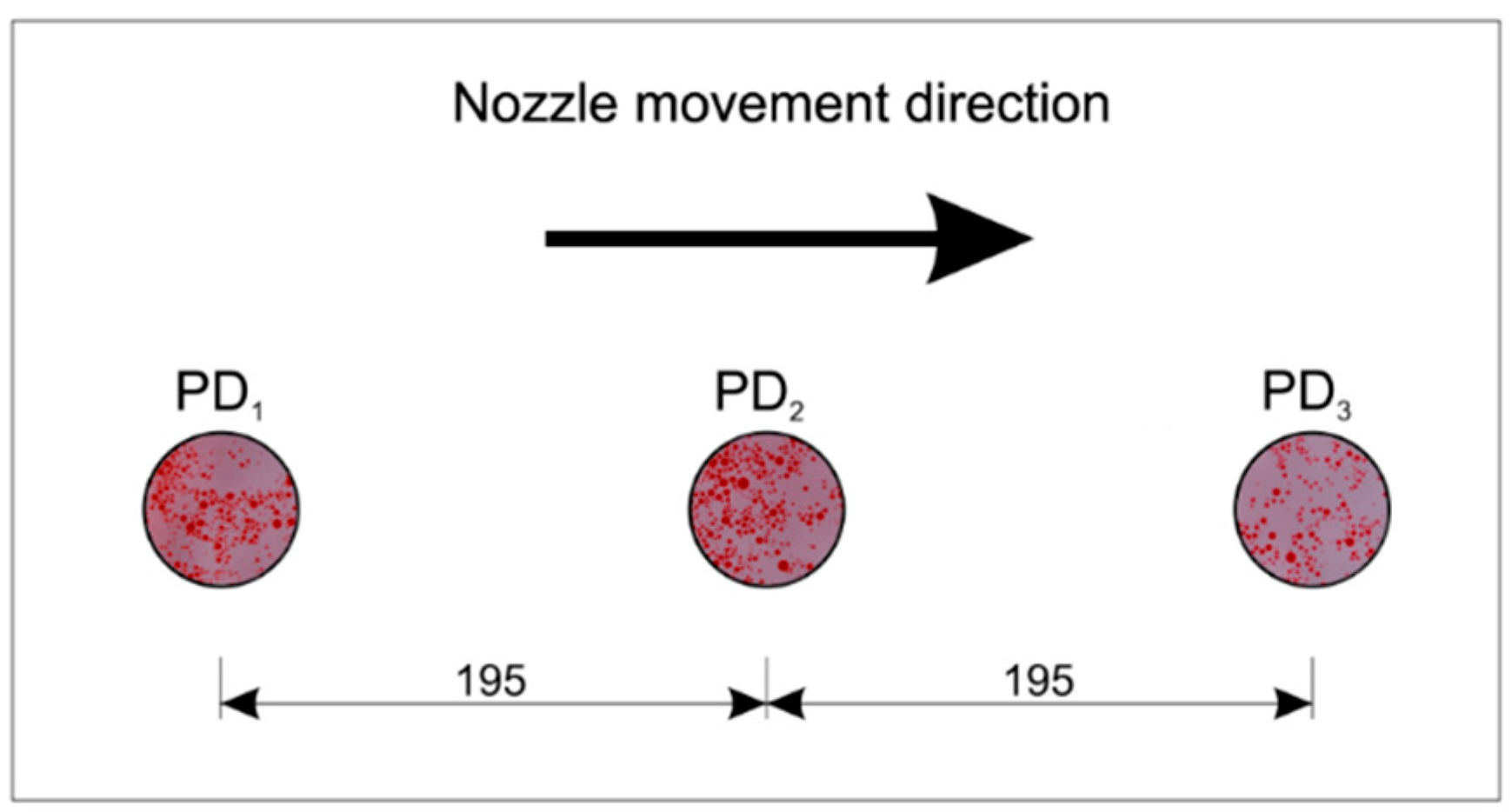
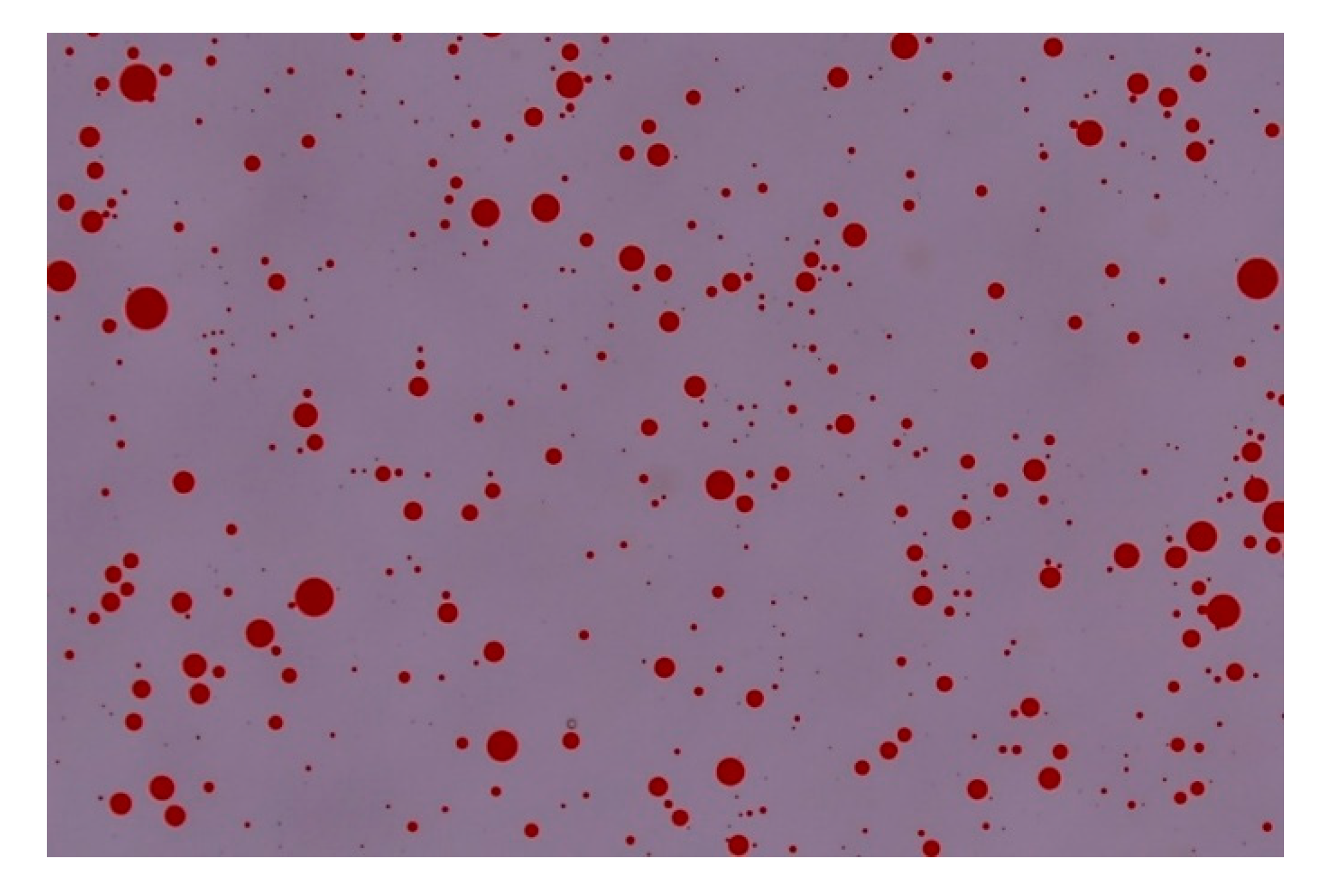
2.6. First Experimental Spraying Tests

These trials were carried out to test the functionality of the whole system and its sensitivity to pressure changes. No proper experimental design was defined, and results were considered as qualitative only. Future experiments and trials will be carried out and presented in other scientific papers, comparing several types of nozzles and testing under the same conditions the reference nozzles used to define the boundary regions of spray quality as recommended by the ISO/FDIS 25358:2018 standard [55]. Spraying tests were carried out with an ATR80 orange hollow cone nozzle (Albuz, France) at the working pressures of 0.3, 0.5, 1.0, and 1.5 MPa, and spraying as test liquid clean water with the addition of red Ponceau (Novema Srl, Torino, Italy) as a soluble coloring agent at the concentration of 2 g/L. In these first trials, surface tension of test liquid was not measured. Temperature and relative humidity of the ambient air were measured by using a thermohygrometer (HD 8901 model from Delta Ohm, Padova, Italy).
The three Petri dishes that were used to sample the drops had a diameter of 55 mm, and the distance between their centers was 195 mm (Figure 5). Nozzle speed during the tests was set to 1.5 m/s.
Five milliliters of silicone oil (AR200 from Sigma-Aldrich, Milano, Italy) were deposited in each Petri dish by using a pipette (Mettler-Toledo, Milano, Italy), taking care to avoid bubble formation. Dynamic viscosity and volumetric mass of the silicone oil were 200 mPa s and 1050 kg/m3, respectively.
After sprays, Petri dishes were photographed in situ by using a Nikon D5500 DSLR (digital single-lens reflex) camera equipped with a macro lens (Nikon Micro Nikkor AF-S 60 mm f/2.8 G ED) and an electronic flash (Neewer 48 Macro LED Ring Flash). To avoid involuntary movements, the camera was remotely controlled via the qDslrDashboard Version 3.5.3 application (http://dslrdashboard.info) running on an Android tablet. Spraying tests were repeated three times, so nine photos were taken for each working pressure. The images were saved as high-quality JPEG files with a resolution of 6000 × 4000 pixels. The red color of the test liquid allowed for an easy recognition of the droplets during the subsequent image analysis (Figure 6).
Images were calibrated by taking photos of a 10 × 10 mm grid pattern engraved on a glass disc, placed in correspondence of the three Petri dish positions, as far from the camera focal plane as the drops. The resulting scale factor ranged from 188.0 to 189.0 pixel/mm for the three Petri dish positions.
All images were analyzed with the ImageJ software, release 1.52a [56]. The use of this software for the spray droplet image analysis is well documented in the literature [44,45]. After conversion in 8-bit grey scale, images were segmented. The selected threshold value was obtained, on the basis of a careful inspection of the images, by increasing the “default” threshold value prompted by ImageJ by 20% on average. A threshold value directly linked to the grey level of the image as described in Sánchez-Hermosilla and Medina [57] was not exploited in this case because it was specifically studied to analyze water sensitive paper images, which are different from actual images, mainly due to the lighting conditions. In future trials, when other types of nozzles will be tested, a specific study will be dedicated to the segmentation process, and it will be checked whether the criterion adopted in this study for the ATR80 hollow cone nozzle is still valid. The ultimate goal will be to attempt to implement a segmentation procedure based on the correlation between some features of the images and the optimal threshold value, similar to that discussed in [57], in order to make the segmentation process as less subjective as possible.
After segmentation, images were processed with the watershed binary filter to separate some touching drops. The area (pixel) of the drops detected by ImageJ in each image was exported in text files for the subsequent analyses. Assuming that the measured area was circular, the droplet diameter was computed according to Equation (2):
D i = 4 A i π
where A i (pixel) is the area of drop i . Particles with an area lower than 5 pixels were ignored. Droplet diameters expressed in pixels provided by Equation (2) were converted into real values by applying the proper scale factor, and then all the drop size distribution parameters were computed. The following quantities were calculated:
  • D 10 , as the arithmetic mean diameter;
  • D 20 , as the surface mean diameter;
  • D 30 , as the volume mean diameter;
  • D 32 , as the Sauter mean diameter (SMD), i.e., diameter of a drop having the same volume to surface area ratio as the total volume of all the drops to the total surface area of all the drops;
  • D v 0.1 , D v 0.5 , and D v 0.9 , as volumetric diameters, below which smaller droplets constitute, respectively, 10%, 50%, and 90% of the total volume;
  • relative span factor (RSF), a dimensionless parameter indicative of the uniformity of the drop size distribution, defined as:
    RSF = D v 0.9 D v 0.1 D v 0.5
  • number mean diameter (NMD), which is the droplet diameter below which the droplet diameter for 50% of the number of drops are smaller;
  • V 100 and V 200 , as percentages of total volume of droplets smaller than, respectively, 100 and 200 µm in diameter.
All computations were carried out by means of custom functions written in R [58].

3. Results and Discussion

3.1. The Whole System Test

Figure 7 shows the main components of the entire system: the water tank with the electric motor pump and the manual pressure regulators; the mobile platform with the nozzle holder and the sensor pressure moving along the two rails; the cabinet with the electric/electronic components; the DSLR camera for drop image acquisition; and the wood table supporting the Petri dishes, which is mechanically insulated from the other parts of the frame.
At the beginning of the experiment, the electric motor driving the pump is switched on, and all the flow is recirculated to the tank (the electro valve of the hydraulic circuit is closed, Figure 1). After the working pressure is chosen and the manual pressure regulator is adjusted accordingly, the whole experiment is managed by the software. The user sets the desired platform speed (acceleration and deceleration are internally computed in the motor drive, according to Equation (1)), the initial delay necessary to reach steady-stay conditions, and the CSV file name to log the pressure, flow rate, velocity and position data. Then, the experiment starts: the mobile platform is carried at the home position (at one end of the rails), the electro valve is switched on, the nozzle starts spraying, and after the delay has elapsed, the platform moves and the test liquid is sprayed over the three Petri dishes containing silicone oil. After one pass, the platform stops at the opposite end of the rails. The distance between the spraying nozzle and Petri dishes is 0.5 m. The images of the drops trapped into the oil are immediately acquired in situ by using the camera.

3.2. Mechanical Tests

Figure 8 and Figure 9 show the capabilities of the system to control speed and position. In particular, Figure 8 reports the position profiles vs. time recorded during the tests, while Figure 9 shows the speed profiles vs. position, directly obtained from the optical encoder. The profiles are almost superimposable for all the tests: The presence of the small quantities of noise is mainly due to limitations of the Windows operating system to accurately measure time intervals less than 100 ms. No malfunctioning was observed during all the experimental activities. In addition, the graphs show the platform reaching the reference speed (1.5 m/s) before approaching the first Petri dish, keeping it constant until going over the last one. The whole trajectory was completed in about 2.3 s.

3.3. Spraying Test Results

Air temperature and relative humidity during the experiments were 26 °C and 43%, respectively. The number of droplets detected in each of the analyzed images ranged from about 1700 to about 38,300. Taking into account all the images, the total number of sampled drops ranged from about 37,800 (0.3 MPa) to about 286,500 (1.5 MPa), much higher than the ISO 5682-1 requirements (representative samples composed by at least 2000 droplets).
Table 1 reports flow rate data for the nozzle under test, and Table 2 summarizes all the measured spray drop parameters in function of working pressures; mean values were computed assuming each Petri dish as an independent sample.
As expected, all diameters were affected by pressure: An increase in pressure determined a decrease in diameters, meaning a higher degree of drop pulverization. The measurement system was then able to correctly detect the influence of pressure changes. According to the Albuz catalogue, the spray quality of the ATR80 orange hollow cone nozzles at 0.5 MPa and over is classified as “very fine”, based upon volumetric median diameter (VMD) D v 0.5 values lower than 159 µm, measured with phase Doppler anemometry (PDA) systems. Therefore, results obtained with the present test bench qualitatively agree with Albuz’s information.
In addition, this measuring system was quite reliable and accurate: In fact, the coefficients of variation (CV) of all diameters (except D v 0.1 at 0.3 MPa and NMD) ranged between 1.9% and 8.6%. In the excluded cases, CVs ranged between 8.5% and 15.0%. As a general result, variability was higher when diameters were lower.

4. Conclusions

The design, development, and construction of a low-cost laboratory test bench suitable to analyze agricultural spray nozzles according to the ISO 5682-1 procedure were discussed in the paper. The preliminary tests show its usefulness under several aspects:
  • The software interface to control the test bench and to set the test conditions is simple, and its organization in tabs (the first to set the test parameters; the second one to see graphically the evolution of the test variables) makes it easy to use the test bench.
  • The hydraulic circuit allows for testing nozzles under work conditions similar to those present in commercial sprayers, using a standard diaphragm pump and standard manual pressure regulators.
  • The electromechanic components allow for a fine and precise control of speed and position of the nozzle under test.
  • The image acquisition system, based on a digital single-lens reflex camera, may be easily updated if higher resolutions are required. The actual system, with a scale factor of 188.0–189.0 pixel/mm, allows for detecting the drops whose diameter is greater than 10 µm, which can be considered suitable for similar applications.
  • In measuring the single drop diameters, it is possible to devise the size diameter probability distribution function and all the usual spray drop parameters. The preliminary tests with the Albuz ATR80 orange hollow cone nozzles produced results in accordance with factory data sheets.
  • Further tests that are aimed at comparing several nozzle types (hollow cone, fan, air induction) with the reference nozzles recommended by ISO/FDIS 25358:2018 [55] to define the boundaries/borders between the size classes may better assess the capabilities of the test bench.
The system also has some limitations due to the specific hardware implementation. The most severe limitation is imposed by the rail length, which does not allow for the maximum speed of the mobile platform, while spraying above the Petri dishes, to be higher than 1.5 m/s. Higher speed values to be kept constant while the nozzle sprays above the Petri dishes would require higher acceleration values, but the maximum acceleration is limited for mechanical/electrical safety reasons. Increasing the platform speed is a practical way to reduce overlaps between drops and then to simplify the subsequent image analysis procedure.
A minor limitation is related to the maximum sample rate of the Advantech Ethernet modules, used for monitoring the position and speed profile and for acquiring data from sensors. The trajectory control loop is achieved via hardware with a 1 kHz sampling frequency, but monitoring and logging operations are left to the Windows operating system, which cannot guarantee a constant sampling rate and good accuracy for time intervals less than 100 ms; thus, the speed and position graphs may result deformed. An optimization of the reading and writing routines and of data filtering may improve these aspects.
Finally, a significant improvement may be introduced in the camera positioning system. The camera is actually applied to a metallic frame, which in turn is manually hanged to the rails in predetermined positions. A better solution could be to hang the camera directly to the mobile platform after the spray passes and then to position it in correspondence of the Petri dishes by exploiting the control position system of the motor. This could speed up the image acquisition procedure and then reduce any effect of external factors.
Finally, taking into account all the above considerations, it is possible to conclude that the main objectives fixed were achieved with the test bench and that its modularity allows for further developments to overcome the limitations highlighted, without compromising the low cost.

Author Contributions

Conceptualization, E.C., D.L., G.M., and R.P.; methodology, E.C., D.L., G.M., and R.P.; software, D.L.; validation, E.C., D.L., G.M., and R.P.; formal analysis, E.C., D.L., G.M., and R.P.; investigation, E.C., D.L., G.M., and R.P.; data curation, E.C., D.L., G.M., and R.P.; writing—original draft preparation, E.C.; writing—review and editing, E.C., D.L., G.M., and R.P. All authors have read and agreed to the published version of the manuscript.

Funding

This research was carried out within the research project “Contributo della meccanica agraria e delle costruzioni rurali per il miglioramento della sostenibilità delle produzioni agricole, zootecniche e agro-industriali. WP1: Impiego sostenibile di macchine irroratrici in serra e in pieno campo”, financed inside the “Linea di intervento 2-dotazione ordinaria per attività istituzionali dei dipartimenti-2016-18-II annualità” of the University of Catania.

Conflicts of Interest

The authors declare no conflict of interest.

Abbreviation

Symbol
a acceleration/deceleration value during transients, m/s2
L a trails section covered by the nozzle at constant acceleration/deceleration, m
L r trails section covered by the nozzle at constant speed, m
t a acceleration/deceleration time (transient time), s
t r time while the nozzle moves at constant speed (steady state time), s
v r desired constant nozzle speed, m/s
A i area of droplet i detected by ImageJ, pixel
D i diameter of droplet i, pixel
D 10 arithmetic mean diameter, µm
D 20 surface mean diameter, µm
D 30 volume mean diameter, µm
D 32 Sauter mean diameter (SMD) or the diameter of a drop having the same volume to surface area ratio as the total volume of all the drops to the total surface area of all the drops, µm
D v 0.1 ,   D v 0.9 volumetric diameters below which smaller droplets constitute, respectively, 10% and 90% of the total volume, µm
D v 0.5 volumetric median diameter (VMD), below which smaller droplets constitute 50% of the total volume, µm
NMDnumber mean diameter, the droplet diameter below which the droplet diameter for 50% of the number of drops are smaller, µm
RSFrelative span factor, a dimensionless parameter indicative of the uniformity of the drop size distribution
SMDSauter mean diameter, µm
VMDvolume median diameter, µm
V 100 , V 200 proportion of total volume of droplets smaller than, respectively, 100 and 200 µm in diameter, %
Acronym
ACAlternated current
CSVComma separated value
CVCoefficient of variation
DCDirect current
DIADigital image analysis
DSLRDigital single-lens reflex
GUIGraphic user interface
IDEIntegrated development environment
IPInternet protocol
LDLaser diffraction
OAPOptical array probes
OIOptical imaging
PDPetri dish
PDAPhase Doppler anemometry
PDPAPhase Doppler particle analyzers
PIDProportional–integral–derivative
PMDCPermanent magnets direct current
PPPPlant protection products
PSUPower supply unit
TCPTransmission control protocol
TCP/IPTransmission control protocol/Internet protocol

References

  1. European Union. Directive 2009/128/EC of the European Parliament and of the Council of 21 October 2009 establishing a framework for Community action to achieve the sustainable use of pesticides. Off. J. L 2009, 309, 71–86. [Google Scholar]
  2. Cox, S. Information technology: The global key to precision agriculture and sustainability. Comput. Electron. Agric. 2002, 36, 93–111. [Google Scholar] [CrossRef]
  3. Zhang, N.; Wang, M.; Wang, N. Precision agriculture—A worldwide overview. Comput. Electron. Agric. 2002, 36, 113–132. [Google Scholar] [CrossRef]
  4. Camilli, A.; Cugnasca, C.E.; Saraiva, A.M.; Hirakawa, A.R.; Corrȇa, P.L.P. From wireless sensors to field mapping: Anatomy of an application for precision agriculture. Comput. Electron. Agric. 2007, 58, 25–36. [Google Scholar] [CrossRef]
  5. Sankaran, S.; Mishra, A.; Ehsani, R.; Davis, C. A review of advanced techniques for detecting plant diseases. Comput. Electron. Agric. 2010, 72, 1–13. [Google Scholar] [CrossRef]
  6. Gil, E.; Arnó, J.; Llorens, J.; Sanz, R.; Llop, J.; Rosell-Polo, J.R.; Gallart, M.; Escolà, A. Advanced technologies for the improvement of spray application techniques in Spanish viticulture: An overview. Sensors 2014, 14, 691–708. [Google Scholar] [CrossRef] [Green Version]
  7. Jiao, L.; Dong, D.; Feng, H.; Zhao, X.; Chen, L. Monitoring spray drift in aerial spray application based on infrared thermal imaging technology. Comput. Electron. Agric. 2016, 121, 135–140. [Google Scholar] [CrossRef]
  8. Escolà, A.; Rosell-Polo, J.R.; Planas, S.; Gil, E.; Pomar, J.; Camp, F.; Llorens, J.; Solanelles, F. Variable rate sprayer. Part 1—orchard prototype: Design, implementation and validation. Comput. Electron. Agric. 2013, 95, 122–135. [Google Scholar] [CrossRef] [Green Version]
  9. Gil, E.; Llorens, J.; Llop, J.; Fàbregas, X.; Escolà, A.; Rosell-Polo, J.R. Variable rate sprayer. Part 2—Vineyard prototype: Design, implementation, and validation. Comput. Electron. Agric. 2013, 95, 136–150. [Google Scholar] [CrossRef] [Green Version]
  10. Pascuzzi, S.; Cerruto, E. Spray deposition in “tendone” vineyards when using a pneumatic electrostatic sprayer. Crop Prot. 2015, 68, 1–11. [Google Scholar] [CrossRef]
  11. Oberti, R.; Marchi, M.; Tirelli, P.; Calcante, A.; Iriti, M.; Tona, E.; Hočevar, M.; Baur, J.; Pfaff, J.; Schütz, C.; et al. Selective spraying of grapevines for disease control using a modular agricultural robot. Biosyst. Eng. 2016, 146, 203–215. [Google Scholar] [CrossRef]
  12. Qin, W.C.; Qiu, B.J.; Xue, X.Y.; Chen, C.; Xu, Z.F.; Zhou, Q.Q. Droplet deposition and control effect of insecticides sprayed with an unmanned aerial vehicle against plant hoppers. Crop Prot. 2016, 85, 79–88. [Google Scholar] [CrossRef]
  13. Grella, M.; Gallart, M.; Marucco, P.; Balsari, P.; Gil, E. Ground deposition and airborne spray drift assessment in vineyard and orchard: The influence of environmental variables and sprayer settings. Sustainability 2017, 9, 728. [Google Scholar] [CrossRef] [Green Version]
  14. Pascuzzi, S.; Cerruto, E.; Manetto, G. Foliar spray deposition in a “tendone” vineyard as affected by airflow rate, volume rate and vegetative development. Crop Prot. 2017, 91, 34–48. [Google Scholar] [CrossRef]
  15. Rao Mogili, U.M.; Deepak, B.B.V.L. Review on application of drone systems in precision agriculture. Procedia Comput. Sci. 2018, 133, 502–509. [Google Scholar] [CrossRef]
  16. Pascuzzi, S.; Santoro, F.; Manetto, G.; Cerruto, E. Study of the correlation between foliar and patternator deposits in a “tendone” vineyard. Agric. Eng. Int. CIGR J. 2018, 20, 97–107. [Google Scholar]
  17. Gan-Mor, S.; Matthews, G.A. Recent developments in sprayers for application of biopesticides—An overview. Biosyst. Eng. 2003, 84, 119–125. [Google Scholar] [CrossRef]
  18. Blandini, G.; Emma, G.; Failla, S.; Manetto, G. A prototype for mechanical distribution of beneficials. Acta Hortic. 2008, 2, 1515–1522. [Google Scholar] [CrossRef]
  19. Pezzi, F.; Martelli, R.; Lanzoni, A.; Maini, S. Effects of mechanical distribution on survival and reproduction of Phytoseiulus persimilis and Amblyseius swirskii. Biosyst. Eng. 2015, 129, 11–19. [Google Scholar] [CrossRef]
  20. Lamichhane, J.R. Pesticide use and risk reduction in European farming systems with IPM: An introduction to the special issue. Crop Prot. 2017, 97. [Google Scholar] [CrossRef]
  21. Papa, R.; Manetto, G.; Cerruto, E.; Failla, S. Mechanical distribution of beneficial arthropods in greenhouse and open field: A review. J. Agric. Eng. 2018, 49, 81–91. [Google Scholar] [CrossRef] [Green Version]
  22. Lee, R.; den Uyl, R.; Runhaar, H. Assessment of policy instruments for pesticide use reduction in Europe; Learning from a systematic literature review. Crop Prot. 2019, 126, 104929. [Google Scholar] [CrossRef]
  23. Mantzoukas, S.; Eliopoulos, P.A. Endophytic entomopathogenic fungi: A valuable biological control tool against plant pests. Appl. Sci. 2020, 10, 360. [Google Scholar] [CrossRef] [Green Version]
  24. Hewitt, A.J. Droplet size and agricultural spraying, part I: Atomization, spray transport, deposition, drift, and droplet size measurement techniques. At. Sprays 1997, 7, 235–244. [Google Scholar] [CrossRef]
  25. Matthews, G.A. How was the pesticide applied? Crop Prot. 2004, 23, 651–653. [Google Scholar] [CrossRef]
  26. Nuyttens, D.; Baetens, K.; De Schampheleire, M.; Sonck, B. Effect of nozzle type, size and pressure on spray droplet characteristics. Biosyst. Eng. 2007, 97, 333–345. [Google Scholar] [CrossRef]
  27. Garcerá, C.; Román, C.; Moltó, E.; Abad, R.; Insa, J.A.; Torrent, X.; Chueca, P. Comparison between standard and drift reducing nozzles for pesticide application in citrus: Part II. Effects on canopy spray distribution, control efficacy of Aonidiella aurantii (Maskell), beneficial parasitoids and pesticide residues on fruit. Crop Prot. 2017, 94, 83–96. [Google Scholar] [CrossRef] [Green Version]
  28. Torrent, X.; Garcerá, C.; Moltó, E.; Chueca, P.; Abad, R.; Grafulla, C.; Planas, S. Comparison between standard and drift reducing nozzles for pesticide application in citrus: Part I. Effects on wind tunnel and field spray drift. Crop Prot. 2017, 96, 130–143. [Google Scholar] [CrossRef] [Green Version]
  29. Torrent, X.; Gregorio, E.; Douzals, J.P.; Tinet, C.; Rosell-Polo, J.R.; Planas, S. Assessment of spray drift potential reduction for hollow-cone nozzles: Part 1. Classification using indirect methods. Sci. Total Environ. 2019. [Google Scholar] [CrossRef]
  30. Berger-Preiß, E.; Boehnckey, A.; Könnecker, G.; Mangelsdorf, I.; Holthenrich, D.; Koch, W. Inhalational and dermal exposures during spray application of biocides. Int. J. Hyg. Environ. Health 2005, 208, 357–372. [Google Scholar] [CrossRef]
  31. Nuyttens, D.; Braekman, P.; Windey, S.; Sonck, B. Potential dermal pesticide exposure affected by greenhouse spray application technique. Pest Manag. Sci. 2009, 65, 781–790. [Google Scholar] [CrossRef] [PubMed]
  32. Sánchez-Hermosilla, J.; Rincón, V.J.; Páez, F.; Agüera, F.; Carvajal, F. Field evaluation of a self-propelled sprayer and effects of the application rate on spray deposition and losses to the ground in greenhouse tomato crops. Pest Manag. Sci. 2011, 67, 942–947. [Google Scholar] [CrossRef] [PubMed]
  33. Sánchez-Hermosilla, J.; Páez, F.; Rincón, V.J.; Carvajal, F. Evaluation of the effect of spray pressure in hand-held sprayers in a greenhouse tomato crop. Crop Prot. 2013, 54, 121–125. [Google Scholar] [CrossRef]
  34. Gil, E.; Balsari, P.; Gallart, M.; Llorens, J.; Marucco, P.; Andersen, P.G.; Fàbregas, X.; Llop, J. Determination of drift potential of different flat fan nozzles on a boom sprayer using a test bench. Crop Prot. 2014, 56, 58–68. [Google Scholar] [CrossRef]
  35. Cerruto, E.; Manetto, G.; Santoro, F.; Pascuzzi, S. Operator dermal exposure to pesticides in tomato and strawberry greenhouses from hand-held sprayers. Sustainability 2018, 10, 2273. [Google Scholar] [CrossRef] [Green Version]
  36. Rincón, V.J.; Páez, F.C.; Sánchez-Hermosilla, J. Potential dermal exposure to operators applying pesticide on greenhouse crops using low-cost equipment. Sci. Total Environ. 2018, 630, 1181–1187. [Google Scholar] [CrossRef]
  37. Lodwik, D.; Pietrzyk, J.; Malesa, W. Analysis of volume distribution and evaluation of the spraying spectrum in terms of spraying quality. Appl. Sci. 2020, 10, 2395. [Google Scholar] [CrossRef] [Green Version]
  38. Schick, R.J. Spray Technology Reference Guide: Understanding drop size. In Spraying Systems Bulletin no. 459C; Spraying Systems Co.: Wheaton, IL, USA, 2008; Available online: https://www.spray.com/literature_pdfs/B459C_Understanding_Drop_Size.pdf (accessed on 11 November 2019).
  39. Lad, N.; Aroussi, E.A.; Muhamad Said, M.F. Droplet size measurement for liquid spray using digital image analysis technique. J. Appl. Sci. 2011, 11, 1966–1972. [Google Scholar] [CrossRef] [Green Version]
  40. De Cock, N.; Massinon, M.; Nuyttens, D.; Dekeyser, D.; Lebeau, F. Measurements of reference ISO nozzles by high-speed imaging. Crop Prot. 2016, 89, 105–115. [Google Scholar] [CrossRef] [Green Version]
  41. De Cock, N.; Massinon, M.; Ouled Taleb Salah, S.; Mercatoris, B.C.N.; Lebeau, F. Droplet size distribution measurements of ISO nozzles by shadowgraphy method. Commun. Appl. Biol. Sci. 2015, 80, 295–301. [Google Scholar]
  42. Hoffmann, W.C.; Hewitt, A.J. Comparison of three imaging systems for water-sensitive papers. Appl. Eng. Agric. 2005, 21, 961–964. [Google Scholar] [CrossRef]
  43. Marçal, A.R.S.; Cunha, M. Image processing of artificial targets for automatic evaluation of spray quality. Trans. ASABE 2008, 51, 811–821. [Google Scholar] [CrossRef] [Green Version]
  44. Zhu, H.; Salyani, M.; Fox, R.D. A portable scanning system for evaluation of spray deposit distribution. Comput. Electron. Agric. 2011, 76, 38–43. [Google Scholar] [CrossRef]
  45. Cunha, M.; Carvalho, C.; Marcal, A.R.S. Assessing the ability of image processing software to analyse spray quality on water-sensitive papers used as artificial targets. Biosyst. Eng. 2012, 111, 11–23. [Google Scholar] [CrossRef] [Green Version]
  46. Cerruto, E.; Aglieco, C.; Failla, S.; Manetto, G. Parameters influencing deposit estimation when using water sensitive papers. J. Agric. Eng. 2013, 44, 62–70. [Google Scholar] [CrossRef]
  47. Salyani, M.; Zhu, H.; Sweeb, R.D.; Pai, N. Assessment of spray distribution with water-sensitive paper. Agric. Eng. Int. CIGR J. 2013, 15, 101–111. [Google Scholar]
  48. Cerruto, E.; Failla, S.; Longo, D.; Manetto, G. Simulation of water sensitive papers for spray analysis. Agric. Eng. Int. CIGR J. 2016, 18, 22–29. [Google Scholar]
  49. Cerruto, E.; Manetto, G.; Longo, D.; Failla, S.; Papa, R. A model to estimate the spray deposit by simulated water sensitive papers. Crop Prot. 2019, 124, 104861. [Google Scholar] [CrossRef]
  50. ISO (International Organization for Standardization). ISO 5682-1, Equipment for Crop Protection—Spraying Equipment—Part 1: Test Methods for Sprayer Nozzles; ISO: Geneva, Switzerland, 2017. Available online: https://www.iso.org/standard/60053.html (accessed on 16 July 2020).
  51. Cerruto, E.; Manetto, G.; Longo, D.; Failla, S.; Schillaci, G. A laboratory system for nozzle spray analysis. Chem. Eng. Trans. 2017, 58, 751–756. [Google Scholar] [CrossRef]
  52. Ali, A.; Awan, A.; Khan, F.H.; Khan, M.A. Fabrication of Ultra Low Volume (ULV) pesticide sprayer test bench. Pak. J. Agric. Sci. 2011, 48, 135–140. [Google Scholar]
  53. Ziegler, G.; Nichols, N.B. Optimum settings for automatic controllers. Trans. ASME 1942, 64, 759–768. [Google Scholar] [CrossRef]
  54. Meshram, P.M.; Kanojiya, R.G. Tuning of PID controller using Ziegler-Nichols method for speed control of DC motor. In Proceedings of the IEEE-International Conference on Advances in Engineering, Science and Management (ICAESM-2012), Nagapattinam, Tamil Nadu, India, 30–31 March 2012; pp. 117–122. [Google Scholar]
  55. ISO (International Organization for Standardization). ISO/FDIS 25358:2018, Crop Protection Equipment—Droplet-Size Spectra from Atomizers—Measurement and Classification; ISO: Geneva, Switzerland, 2018. Available online: https://www.iso.org/standard/66412.html (accessed on 26 June 2020).
  56. Abramoff, M.D.; Magelhaes, P.J.; Ram, S.J. Image processing with Image. J. Biophot. Int. 2004, 11, 36–42. [Google Scholar]
  57. Sánchez-Hermosilla, J.; Medina, R. Adaptive threshold for droplet spot analysis using water-sensitive paper. Appl. Eng. Agric. 2011, 20, 547–551. [Google Scholar] [CrossRef]
  58. R Core Team. R: A Language and Environment for Statistical Computing; R Foundation for Statistical Computing: Vienna, Austria, 2019; Available online: https://www.R-project.org (accessed on 1 May 2020).
Figure 1. Scheme of the hydraulic circuit (blue: low pressure line; red: high pressure line; S: electro valve; FS: flux sensor; PT: pressure transmitter).
Applsci 10 05221 g001
Figure 2. Partial section of the test bench showing its main components.
Applsci 10 05221 g002
Figure 3. Block diagram of the control system architecture.
Applsci 10 05221 g003
Figure 4. User interface: (a) tab used to manage the spray trials and set the working parameters; (b) tab used to monitor the sensor signals and to stop the system in case of emergency.
Applsci 10 05221 g004
Figure 5. Positioning of the Petri dishes (PD) on the table of the test bench (sizes in mm).
Applsci 10 05221 g005
Figure 6. Droplets trapped into the silicone oil.
Applsci 10 05221 g006
Figure 7. Main components of the test bench: (a) the whole system with the digital single-lens reflex (DSLR) camera and the wood table; (b) the main tank with the electric motor pump and the pressure regulators; (c) the mobile platform with the nozzle holder and the sensor pressure; (d) the cabinet with the electric components.
Applsci 10 05221 g007
Figure 8. Position profiles of the mobile platform during the tests.
Applsci 10 05221 g008
Figure 9. Speed profiles of the mobile platform during the tests.
Applsci 10 05221 g009
Table 1. Measured and reference flow rate values for the nozzle under test.
Measured ValuesFrom Nozzle Data Sheets
Pressure, MPaFlow Rate, L/minPressure, MPaFlow Rate, L/min
0.3080.88
0.5170.980.50.99
1.0361.371.01.39
1.4921.631.51.69
Table 2. Spray drop parameters in function of working pressures.
0.3 MPa0.5 MPa1.0 MPa1.5 MPa
ParameterMeanStd DevMeanStd DevMeanStd DevMeanStd Dev
D 10 (µm)81.77.169.72.456.64.954.64.4
D 20 (µm)98.06.783.12.669.14.766.64.5
D 30 (µm)113.16.495.83.582.04.179.04.6
D 32 (µm)150.67.4127.57.6115.43.2111.14.7
D v 0.1 (µm)97.110.979.64.069.93.466.24.1
D v 0.5 (µm)173.47.3148.59.9138.45.1135.63.9
D v 0.9 (µm)264.411.0236.59.0227.34.4219.06.2
RSF0.970.081.060.061.140.041.130.03
NMD (µm)68.310.261.45.245.36.144.25.7
V 100 (%)11.63.322.04.425.82.628.72.9
V 200 (%)65.83.377.74.081.31.484.01.8

