Abstract
A comparative study of glass fiber content (Gc) measurement methods was conducted using actual glass fiber reinforced plastic laminates from the hull plate of a 26-ton yacht. Two prototype side hull plates with the design Gc (40 wt.%) and higher Gc (64 wt.%) were prepared. Four methods were used to study the samples: the calculation method suggested by classification societies’ rules; two direct measurement methods using either calipers and scales or a hydrometer; and the burn-off method, wherein the resin matrix is combusted from the laminates. The results were compared and analyzed to identify the accuracy and benefits of each method. The rule calculation method was found to be effective if the quality of the manufacturing process is known. However, fabrication errors in the laminate structures cannot be detected. Additionally, while direct methods are used to measure the density of glass fibers using measurements of the densities of raw materials and laminates, the volume of inner defects occurring during the fabrication of laminates could not be considered. Finally, it was found that the burn-off method measures Gc and considers the defect volume (voids) inside laminates as well as the non-uniformity of the external shape.
1. Introduction
Glass fiber reinforced plastics (GFRPs) have been widely used for decades for building small ships, such as fishing boats and yachts [1,2], as they exhibit good specific strength, corrosion resistance, and excellent workability. Many GFRP ships are manufactured with a large design margin, as this enables faster and cheaper production. However, it also results in heavier vessels due to the thicker GFRP laminate structures. Laminate structures for composite ships are considerably thicker than those used for aviation and automobile components, which can cause adverse structural effects such as fatigue over the ship’s lifetime [3]. In addition, GFRPs have elicited environmental concerns related to their poor recyclability and issues during drying and disposal [4,5]. Accordingly, increased research attention has been directed toward the optimal design and weight reduction of GFRP ships.
The design regulations for GFRP structures of small crafts are addressed in the international standard ISO 12215-5 [6]. The laminate thickness, controlled by the number of glass fiber cloth layers (plies), is designed based on ship variables such as hull shape, displacement, speed, and hull form, as well as structural variables such as the layout of stiffeners, design loads, and the design of the composite material (type of reinforcement material, reinforcement method, and mechanical properties) [7,
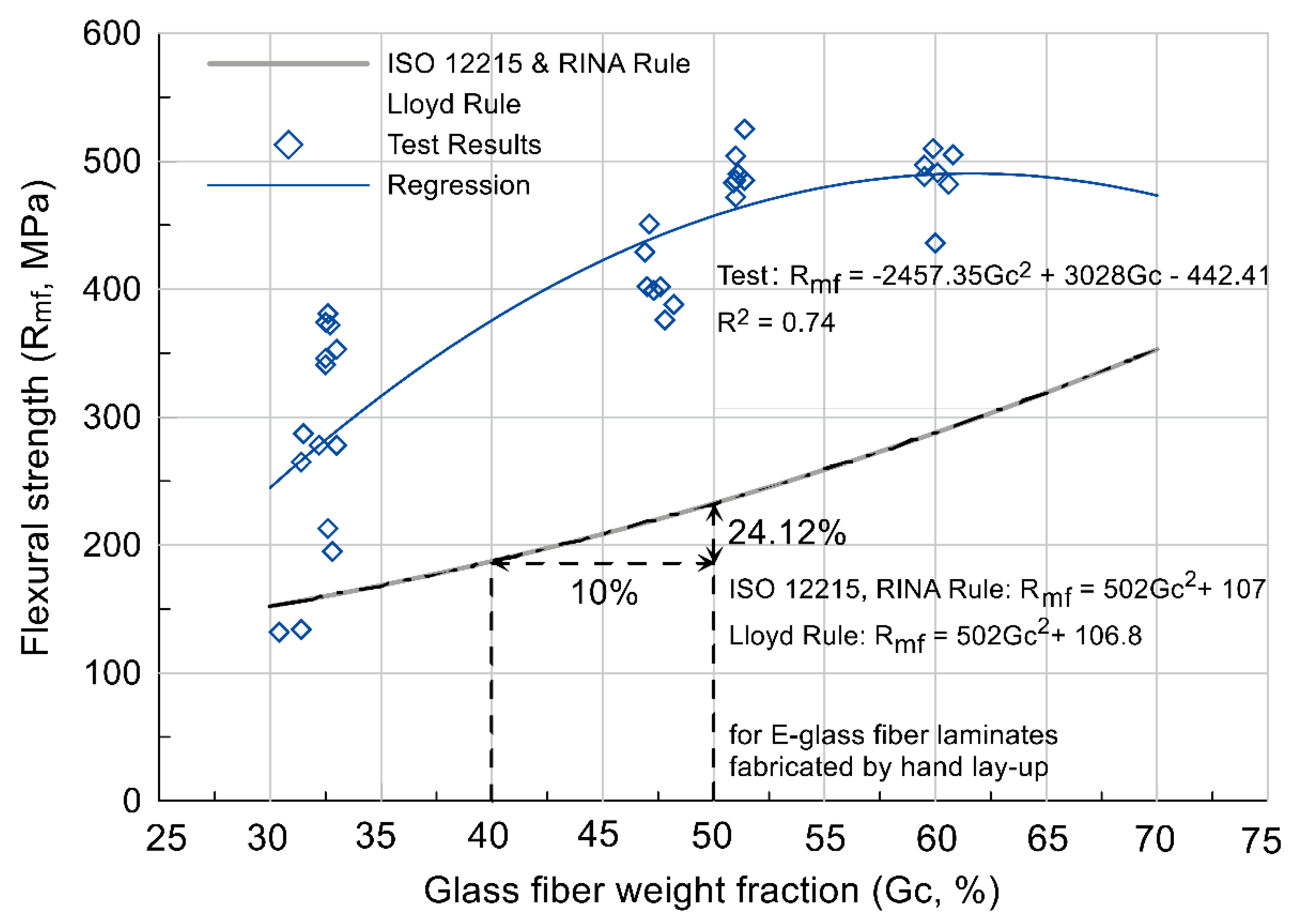
8]. The glass fiber weight fraction, Gc, is a critical design element that significantly affects the mechanical properties of the laminate. The ISO standards and classification society rules provide equations for estimating the mechanical properties of laminate structures according to variations in Gc. These theoretical equations are also differentiated according to the type of glass fiber, reinforcement method, number of plies, and amount of resin used [6,9,10].
However, while Gc is an important indicator of the fabrication quality of a laminate structure [11], the quality of the laminate can vary widely according to the manufacturing method, environment, and operator skill level. GFRP ships are typically manufactured using the hand lay-up method, which can lead to degradation of the glass fiber or resin due to human error [12,13]. Moreover, the laminate structures often contain fabrication defects, such as porosity or voids. These fabrication defects can have a significant impact on the physical performance of the laminate structure, even if Gc meets the design parameters [14,15,16].
For ships that adopt special glass fibers, special structures, or structures thinner than the rules allow, classification societies require manufacturers to disclose the Gc of the laminate structure along with the results of material tests. The mechanical properties are often verified by fracture testing according to the ASTM standards [3,7,11,17], while experimental methods (e.g., resin burn-off) or theoretical calculations are recommended to determine Gc. Nevertheless, the classification rules do not provide detailed specifications on determining Gc. In addition, because of the flexible fabrication characteristics and different types and combinations of materials, it is difficult to verify that laminates are fabricated according to the designed Gc.
To aid the design and manufacture of GFRP laminates for shipbuilding, it is critical to identify an accurate and consistent method of determining Gc. The method should also measure the size and volume of voids inside the laminate structure, as well as the measurement error of the outer shape. Considering the diverse methods currently in use to determine Gc and defect incidence, a comparative study of the different methods is of significant applicative interest. Herein, we empirically tested four different methods of measuring the Gc of GFRP ship components: a widely used theoretical calculation proposed in the classification rules; direct measurement of the volume and weight or relative density of a specimen followed by calculation of Gc; and the burn-off method, wherein the resin matrix is combusted from the laminate. The methods were used to assess two types of composite hull plates for a 16-m ship. A comparative analysis of the results methods was then conducted to determine:
- The reliability of each method for analyzing the laminate structure and establishing the manufacturing precision according to the material design
- The accuracy of each method for testing the fabrication quality of the laminate structure
- The advantages and disadvantages of each method
Overall, we found that the calculation method is effective at measuring Gc if the quality of the manufacturing process is known, but that it cannot detect fabrication errors. The direct measurement methods are also unsuitable for determining the volume of inner defects. In contrast, the burn-off method can accurately measure Gc, the defect volume, and the non-uniformity of the external shape; hence, this method is recommended for ship design when the exact Gc and fabrication quality need to be known. There has been considerable research in other industries on fiber-reinforced composites. However, limited research has been conducted on the use of GFRPs in shipbuilding. Therefore, we expect that this comparative study on methods for assessing laminate structures of actual GFRP ship components will provide a good reference for GFRP ship design.
2. Theoretical Section
2.1. Mechanical Properties and Fabrication Defects of Laminate Structures
The bending strength of the laminate determines the thickness required to build a specific component. Figure 1 shows how the flexural strength of GFRP structures vary with Gc based on the results of estimation equations in ISO 12215-5 [6] and the rules of two classification societies—Lloyd’s Register (LR) [9] and Registro Italiano Navale (RINA) [10]—in comparison to bending test results (according to ASTM D790) of actual GFRP laminates with 4- to 12-ply woven roving cloth with a weight per unit area of 570 g/m2 [16]. The bending strength improves as Gc is increased. However, the experimental results are generally larger than the theoretical values owing to the safety margin included in the standards and classification rules. The test results indicate that the bending strength begins to decrease when Gc increases above 50 wt.% [6]. This is because a high Gc increases the probability of defects and resin-poor regions. The measured bending strengths of some samples with a Gc of 30–35 wt.% showed a significant decrease, which is likely because these specimens were taken from a heterogeneous section of laminate. In other words, to ensure the desired physical performance of laminate parts, the actual Gc should correspond to the design value. The fabrication quality is also important; Figure 2a shows the typical lamination defects that appear in fiber-reinforced composites, and Figure 2b shows inner defects in a carbon fiber-reinforced laminate detected by computed tomography (CT).
Figure 1.
Variation in laminate flexural strength with Gc as determined by international rules and material tests.
Figure 2.
Defects in fiber-reinforced plastic laminates: (a) Schematic of common lamination defects [18]; (b) X-ray CT image of defects in carbon-fiber-reinforced plastic laminate [19].
2.2. Measurement of Weight Fraction of Glass Fiber (Gc) of Laminate Structure
As shown in Figure 2b, destructive methods such as CT testing allow the accurate measurement of inner defects such as void content. However, this method is not practical for the analysis of ship structures owing to the need for specialized equipment and technicians, which are typically not available during ship building. Therefore, we used the following four practical and simple methods to measure, compare, and analyze the GFRP laminate specimens:
- Arithmetic calculation of Gc based on material design, as per ISO 12215 and other classification rules.
- Calculation of the volume of laminate specimens using tools such as Vernier calipers, followed by calculation of Gc.
- Measurement of the specific gravity of laminate specimens using Archimedes’ principle, followed by calculation of Gc.
- Burn-off method involving combustion of the matrix, as suggested by ASTM D3171-15, followed by weight measurement of the glass fiber to determine Gc.
This section summarizes the procedures for these four methods and their application to laminate structures.
2.2.1. Rule Calculation
International standards and classification societies provide rules for ship design, with formulas to calculate Gc and the mechanical properties of the laminate, as well as the required thickness of the laminate structure, by considering the Gc and the hull shape [7]. This process is called “scantling” in ship design. The rule calculations allow easy estimation of Gc from the properties of the fiber cloth and resin and are widely used for the structural design of composite ships. Gc can be calculated from the densities of the glass fiber and cured resin and the thickness of the laminate structure. ISO 12215 and classification society rules suggest that the glass fiber and resin densities should be taken as 2.56 and 1.2 g/cm3, respectively, resulting in Equation (1) for calculating Gc [6].
where t is the laminate thickness (mm) and w is the weight of the glass fiber cloth per unit area (kg/m2).
Gc = 2.56/(3.072 × t/w + 1.36) × 100,
The thickness of a single impregnated ply, Tsingle ply, can be obtained from the thickness of the laminate structure, t, as follows:
where w is the weight of the glass fiber in a single ply of laminate (kg/m2).
Tsingle ply = w/3.072((2.56/Gc) − 1.36),
2.2.2. Direct Measurement
One of the simplest approaches for experimentally determining Gc is to measure the dimensions and weight of a section of the laminate structure using Vernier calipers and an electronic scale, respectively. By assuming a perfect cuboid shape (volume = cross − sectional area × thickness), the relative density, ρc (g/cm3), can be calculated (Equation (3)). The relative density can then be used to calculate Gc based on the theoretical densities of the glass fiber and resin (Equation (4)).
where M is the weight of the laminate specimen (g), A is the cross-sectional area (m2), and t is the thickness (mm); p is the weight of one sheet of reinforcement per unit area (g/m2), and N is the number of sheets in the specimen.
ρc = M/(A × t × 1000),
Gc = (p × N × 0.1)/(ρc × t) × 100
This method is both theoretically and experimentally simple. However, the volume and weight of the cut specimen must be measured accurately. The specimen density is often only approximated from measurements taken using Vernier calipers and a scale if the laminate specimen has rough or irregular surfaces; therefore, it is more accurate to measure the relative density directly using Archimedes’ principle and an instrument such as an immersion electronic densimeter. ASTM D792-13 [20] proposes a procedure for measuring the relative density of plastics, which can be used as a reference. The measured result can then be used in Equation (4).
For both these methods, it is important that the measurements are accurate, and that the density of the glass fiber and uncured resin are known accurately. ISO 12215, LR, and RINA [9,10] prescribe the method described in ISO 1172 [21] for density measurements to confirm those reported in the catalog. However, the inner defects in the structure (see Figure 2) cannot be considered with either method. This can lead to an inaccurate measurement of Gc.
2.2.3. Matrix Burn-Off
To accurately measure Gc and the volume of inner defects, such as porosity, voids, and delamination, ISO 12215 and the classification society rules recommend the use of combustion methods whenever possible. However, this method is not widely used because the process is inconvenient and requires special equipment, and it is considered optional. ASTM D3171-15 [22] proposes two methods for determining the percentages of the raw materials contained in composite materials by removing the matrix. The first method is digestion, which involves chemical removal of the matrix phase, while the other involves the burn-off of the matrix in a furnace. The fibers used in GFRP ship structures can be deformed by the acid solvent used for digestion; therefore, the burn-off method is more appropriate.
After calcining the matrix of the laminate structure, Gc can be determined by comparing the weight of the specimen before and after combustion. This is calculated as follows:
where Mi and Mf are the weights (g) of the specimen before and after combustion, respectively.
Gc = Mf/Mi × 100,
The burn-off method has the advantage of allowing the matrix resin to be calcined slowly, which provides an accurate characterization of the quality of the laminate structure. Moreover, by dividing Equation (5) with the weight of the specimen before and after combustion, the volume of the voids can be obtained [22]:
where ρf and ρr are the densities (g/cm3) of the glass fiber and resin, respectively.
Vvoid = (1 − Mf/Mi × ρc/ρf − (Mi − Mf)/Mi × ρc/ρr) × 100,
2.3. Selection of Glass Fiber Content Measurement Method
The principles and special properties of the methods described above for measuring the Gc of laminate structures for composite ships are summarized in Table 1. Among these methods, the digestion method was excluded because of the possibility of deformation of the raw material and because it is a time-consuming process [23]. To compare the other four methods in more detail, we applied each method to calculate Gc in laminate specimens taken from the side hull plate of a 16-m composite ship. The results are described and compared below.
Table 1.
Comparison of determination methods for Gc.
3. Experimental Methods
Fabrication of Composite Ship Hull Plate and Sample Characterization
The ship tested herein was a 16-m GFRP yacht with a displacement of 26 tons. The primary raw materials in the structure are chopped strand mat (CSM; weight of dry fabric per unit area: 450 g/m2) and polyester resin. For the hull, which is the primary structure of the ship, 20-ply CSM was used for the bottom plate, and 16-ply CSM was used for the side plates. Figure 3 shows the primary structure of this ship, the structural layout of the hull, and the fabrication design for the hull plate.
Figure 3.
Details of the target ship structure and hull plate.
For the composite structures used in the experiment, a hull side plate was fabricated with 16-ply CSM containing 40 wt.% glass fiber, in accordance with the fabrication design (Figure 4). Another prototype laminate structure based on the shape of the side plate, but with a different thickness, was designed by increasing the amount of glass fiber. The higher-Gc laminate structure was designed according to the ISO 12215-15 and RINA design rules; by intentionally increasing the design Gc to 64 wt.%, the number of plies of cloth was increased while the amount of resin was reduced to fabricate a composite hull structure with a higher Gc and smaller thickness. Both laminate structures were fabricated using the vacuum infusion method. Table 2 shows the material design of the two laminate structures, and Figure 4 shows the designs of the two prototypes and the fabricated hull plates. Four specimens were cut and prepared from each laminate structure.
Figure 4.
Dimensions of two hull plates and fabricated prototypes.
Table 2.
Material design for fabrication of two hull side plates.
4. Results
4.1. Specimen Size
The four specimens cut from each laminate structure are shown in Figure 5. Figure 6 shows detailed photos of the #1 laminate specimens with designed Gc values of 40 and 64 wt.%, respectively, indicating the defects generated during the fabrication process. The dimensions obtained for each specimen are listed in Table 2 and Table 3.
Figure 5.
Specimens cut from two hull plates.
Figure 6.
Detailed comparison of 40 and 64 wt.% Gc specimens.
Table 3.
Dimensions of specimens taken from designed hull plate with Gc of 40 wt.%.
4.2. Gc Measurements
The four measurement methods summarized in Table 1 were used to determine Gc of the laminate sections with different design Gc values. The fabrication quality of the laminate structure was confirmed by establishing whether glass-fiber reinforcement was included as specified in the material design. The volume of defects and voids in the laminate structure was also determined. By comparing and analyzing the measurement results obtained using each method, we propose the most suitable method for use in optimized ship design.
4.2.1. Rule Calculation
When Gc is determined from the material design, it is possible to calculate the expected thickness and weight according to the method suggested by the rules; by working backward, Gc can be easily calculated from the fabricated structures. The thicknesses of the side plates of the hull were 11.84 mm for the Gc 40 wt.% design and 9.36 mm for the Gc 64 wt.% design. The side plates were scantled according to the RINA [10] rule (Table 2). The weight per square meter of the laminate structure can be calculated based on the material information used for the construction of this ship (Table 2). Furthermore, from Equation (2), the thickness of a single-ply with 40 wt.% Gc was determined to be 0.74 mm, whereas that with 64 wt.% Gc was 0.39 mm; when the ply number of each structure was applied, the weights of the two structures were 18 and 16.88 kg/m2, respectively (Table 2). Using the calculations in Equation (1) yields Gc values for the two structures of 40 and 64 wt.%, respectively.
4.2.2. Simple Direct Measurement
For the simple direct measurement, the dimensions of the specimen were measured with Vernier calipers (Table 3 and Table 4), and the weight was measured with an electronic scale (Figure 7). The results were used to calculate Gc of the specimens with Equations (3) and (4). In this process, some weights of the CSM cloth were also measured with an electronic scale and applied to the Gc calculation. Table 5 shows the calculated Gc results for the eight laminate specimens.
Table 4.
Dimensions of specimens taken from design hull plate with Gc of 64 wt.%.
Figure 7.
Weight measurement of specimens using an electronic scale.
Table 5.
Gc calculation result for specimens based on simple direct measurements.
Compared to the design Gc values of 40 and 64 wt.%, the simple direct measurements revealed average Gc differences of +0.67 and +2.39 wt.%, respectively. This variation is likely due to the differences between the densities of the glass fiber and polyester resin proposed in the rule and the actual values. In addition, errors occurring during laminate fabrication, perhaps resulting from the technical skills of a worker or a difference in shape volume, may also contribute to the discrepancy. The measured thicknesses of the laminate specimens (Table 3 and Table 4) differed compared to the designed values by an average of +0.10 mm and −0.25 mm for Gc 40 and 64 wt.%, respectively. In other words, these results indicate that the error arises from differences in the external shape of the specimens, rather than from differences between the actual densities of the raw materials and the values specified in the rule.
4.2.3. Archimedes’ Measurement
The relative densities of the hull plate specimens were measured in accordance with ASTM D792-13 [20] using a water immersion hydrometer with a precision of 0.01 g/cm3 (Figure 8). For precise verification, the densities of the CSM cloth and cured polyester resin were also measured (Table 6); the average values were 2.56 and 1.22 g/cm3, respectively, which are similar to the values suggested in the classification rules. The Gc of each hull plate specimen was calculated by using the measured density values (Table 6 and Table 7) in Equation (2), and the results are listed in Table 8.
Figure 8.
Measurement of the relative densities of CSM cloth, polyester, and hull plate using hydrometer.
Table 6.
Densities of raw materials derived from hydrometer measurements.
Table 7.
Measurement of specimen densities using a hydrometer.
Table 8.
Calculated Gc values of specimens measured using a hydrometer.
For the specimens with design Gc of 40 and 64 wt.%, the measurement results showed differences of −0.07 and +2.55 wt.%, respectively, relative to the design Gc, and differences of −0.74 and −0.17 wt.%, respectively, relative to the average value of the Gc determined using the simple direct measurement. Overall, the results tend to be similar to those of the simple direct measurement; the slight difference is the result of volumetric error for the specimen. Therefore, the results measured using a hydrometer were more accurate. The volume measurement using the hydrometer indicates that there is no apparent defect, but it can be imagined that a higher vacuum was applied with a larger amount of E-glass fibers during the fabrication of the higher Gc laminate and that the thickness was slightly reduced. Overall, the direct measurement method indicates that the laminate structures were generally fabricated well and without significant quality defects resulting from incorrect scantling dimensions and non-uniformity of the external shape. In addition, the densities of the constituent materials are similar to those proposed in the design rules.
4.2.4. Burn-Off Method
In the burn-off method, a 4.5-L electric muffle furnace (CORE TECH, HQ-DMF 4.5, Figure 9) with a heating limit of 1200 °C was used to remove polyester from both laminate structures. The procedure described in ASTM D792-13 [20] was followed. The heating temperature and time were set to 600 °C and 3 h, respectively, in accordance with prior work utilizing muffle furnaces [12,24]. At 30-min intervals, the temperature inside the furnace and the weight of the specimen were measured, and then combustion was continued. This process was repeated until the weight change of the specimen was less than 0.001 g. Figure 9 and Figure 10 summarize the burn-off test procedure for the laminate.
Figure 9.
Burn-off method for the combustion of laminate specimens.
Figure 10.
Burn-off test procedure for laminate structures, according to ASTM D792.
Figure 11 and Figure 12 show the burn-off test results for specimen #1 with Gc 40 and Gc 64 wt.%. The resin was calcined rapidly during the first hour of heating. Furthermore, as the laminate was carbonized, the specimen gradually turned white. Table 9 and Table 10 summarize the results of the burn-off tests and present the calculated Gc values based on the weight of the glass fiber remaining after the resin matrix was completely burned away.
Figure 11.
Changes in weight of specimen due to combustion (Gc 40 wt.%, Specimen #1).
Figure 12.
Changes in weight of specimens due to combustion (Gc 64 wt.%, Specimen #1).
Table 9.
Gc calculation result obtained from the burn-off method (design Gc 40 wt.%).
Table 10.
Gc calculation result obtained from the burn-off method (design Gc 64%).
The burn-off test confirmed that the specimens with a design Gc of 64 wt.% exhibited faster calcination of the resin, with complete burn-off completed approximately 30 min faster. Figure 13 shows the progression of the laminate weight change during combustion for each sample.
Figure 13.
Changes in laminate weight during combustion.
The average Gc values measured using the burn-off method were 38.39 and 61.86 wt.% for the hull plates with design values of Gc 40 and 64 wt.%, respectively. These values respectively differ from the design values by −1.61 and −2.14 wt.%; from those obtained with the simple direct measurement by −2.28 and −4.53 wt.%; and from those obtained with the hydrometer method by −1.54 and −4.69 wt.%. Overall, it was confirmed that the weight fraction of the glass fiber was lower than the values obtained using the other measurement methods. This may be due to the volume of inner defects in the laminate (shown in Figure 2). The 40 wt.% Gc specimens seem to be affected by small porosities resulting from areas rich in resin, while in the 64 wt.% Gc specimens, the increase in the number of plies used may have caused delamination between the cloth layers and voids in resin-poor areas. As these specimens were fabricated by the infusion method and were well-fabricated without a significant quantity of defects, as was apparent from the previous hydrometer measurements, the overall void volume must be the total volume of many small voids. In particular, it was confirmed that an increased number of voids was present in the specimens of the hull plate with a high Gc.
Figure 14 shows the void volumes for the specimens of the two hull plates according to Equation (6). Although the volume fraction of the voids is small, this has a significant influence on the weight fraction of glass fiber.
Figure 14.
Volume fraction of voids in the specimens, measured by the burn-off method: (a) design Gc 40 wt.%; (b) design Gc 64 wt.%.
5. Discussion
The Gc values of the two hull plates with different design Gc were verified through four methods. 
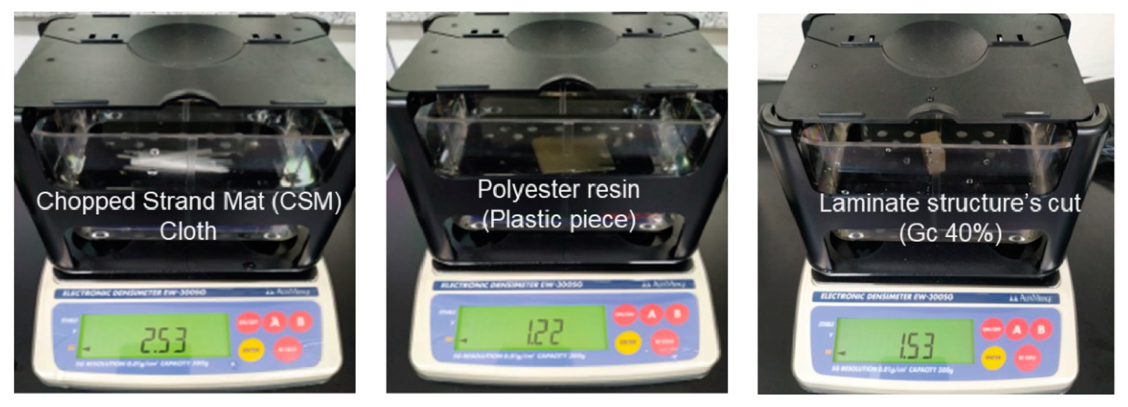
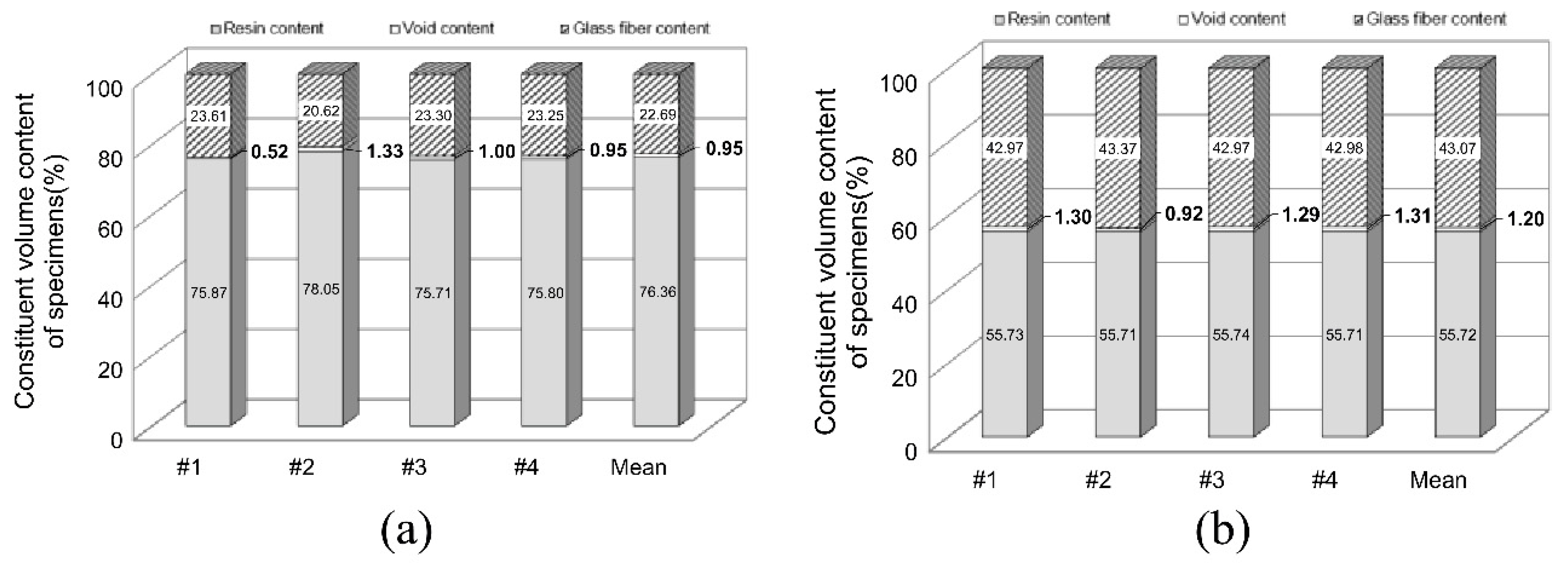
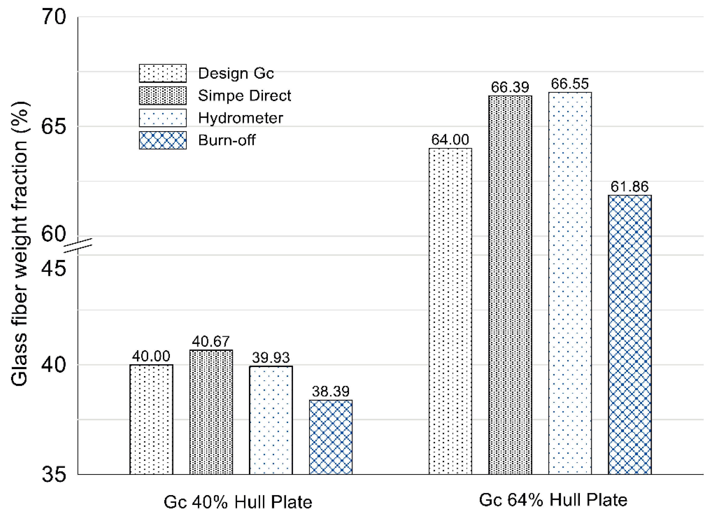
Figure 15 shows a comparison of the experimental results. The differences between the Gc values obtained by the simple direct measurement and hydrometer method were not significant, because the error in the measurement of the external volume was relatively small. Therefore, the discrepancies in the results obtained using the burn-off method are likely due to differences in the volume of inner defects, such as voids. In other words, it was found that the volumes of hull plates with design Gc values of 40 and 64 wt.% contained voids with volumes comprising 0.95 and 1.20 wt.% of the total volume. As shown in Figure 14, the larger difference in the measured results for the Gc 64 wt.% hull plate can be considered to arise from the fabrication qualities of the laminate structures. Furthermore, although these are relatively well-fabricated prototypes produced using the vacuum infusion method, the differences in the results are not negligible. For example, the 2.14 wt.% difference in Gc obtained in the burn-off measurement method for the hull plate with a design Gc value of 64 wt.% corresponds to a decrease in the bending strength of the laminate of about 4.32%, based on the ISO 12215 equations.
Figure 15.
Comparison of Gc values measured by the rule calculation, direct measurement, and burn-off methods.
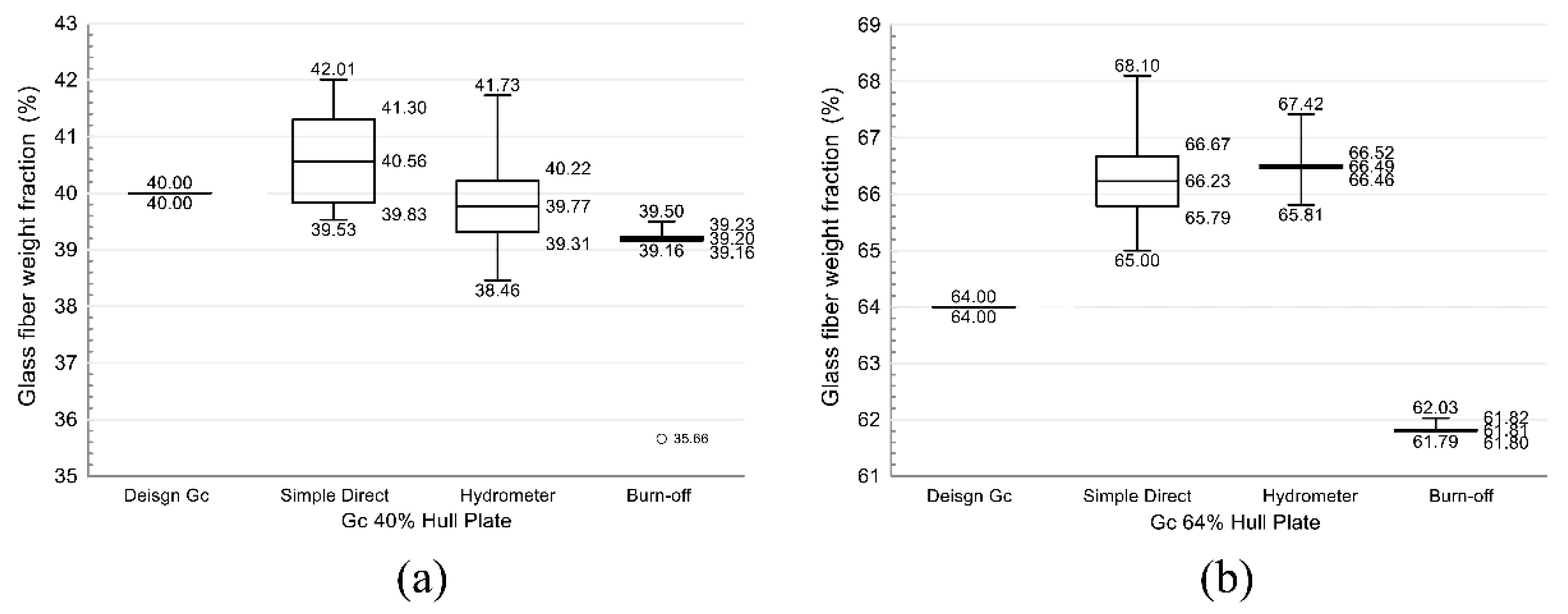
The experimental results are summarized in the form of a box plot, as shown in Figure 16. In the case of the 40 wt.% Gc hull plate, the shape, including the thickness, corresponded well with the design. Nevertheless, nonuniform impregnation of the polyester resin can be confirmed by the deviation in Gc value shown in Figure 15. In particular, as shown in Figure 14, specimen #2 (with a Gc of 35.66 wt.%) contained a relatively large volume of voids and polyester. In the case of the hull plate with a Gc of 64 wt.%, it can be confirmed from the increased Gc seen with the simple direct and hydrometer measurement methods that the pressure of the air compressor was slightly excessive during infusion. This was done to achieve the high Gc level, and it was confirmed that they were fabricated with a thickness slightly below the design thickness. However, this does not constitute an increase in the actual Gc value, but rather an increase in the internal void volume. This resulted in a lower E-glass fiber content, relative to the content specified in the design, and this was confirmed in the burn-off measurement results.
Figure 16.
Gc distribution of specimens measured by different methods: (a) design Gc 40 wt.%; (b) design Gc 64 wt.%.
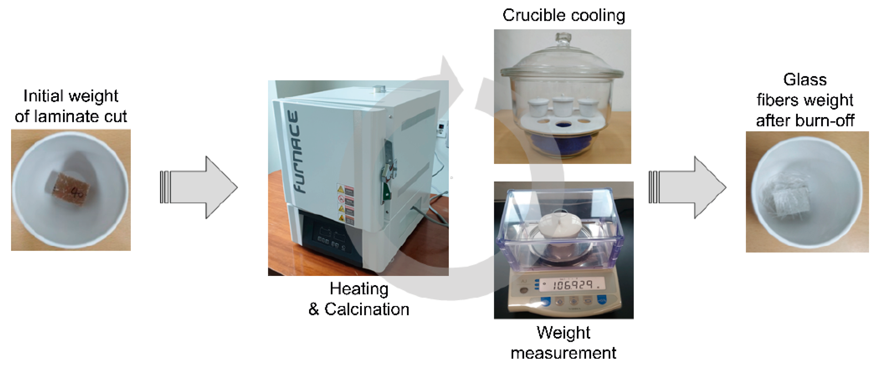
The results of each measurement method may be summarized as follows: the rule calculation can be used very quickly and efficiently if the ship design and material design are known. However, depending on the manufacturing quality of laminate structures, the errors in the measurements of physical properties may increase, and these errors cannot be confirmed. To reduce this error, it is reasonable to use the density suggested by the manufacturer or the density measured directly, rather than use the density of the fiber and resin suggested by the rule. In the simple direct measurement, the differences in shape between the design and laminate can be easily compared. In particular, it is easy to identify key errors from the comparisons of laminate thicknesses and weights. Nonetheless, it is preferable to use a device such as a hydrometer to identify apparent quality defects involving the density of raw materials or the non-uniformity of the external shape. However, with these methods, the effect of internal defects on Gc cannot be identified. Using the burn-off measurement method, suggested in the rules of classification societies, it was possible to measure Gc most accurately, and defects in laminates, including voids, could also be measured very accurately. However, this method requires specialized knowledge regarding analysis with the equipment used for combustion.
6. Conclusions
In this study, the Gc values of two hull plates of composite ships with different glass fiber weight fractions were measured using rule calculation, simple direct measurement, hydrometer, and burn-off methods, with the aim of identifying the change in fabrication quality resulting from quantitative changes in Gc. Because laminate structures for hull plates are typically fabricated by mixing two or more cloths in building yards, large differences can occur between the fabricated laminate structure and the designed structure. The following conclusions were obtained with these practical measurement tests.
Because the rule calculation suggested by classification societies is based on statistics and long-term experience, a logical and relatively accurate Gc value can be calculated for laminate structure design. For more accurate structure determinations, direct measurements using tools such as a hydrometer are recommended. However, only the combustion method was able to measure both the volume of internal defects and Gc with high accuracy.
Overall, it is reasonable to conclude that, in the case of a high-performance ship or a ship built using new materials, it is significantly important to ensure performance by verifying the weight fraction of glass fibers through the use of an accurate test method such as the burn-off method.
Author Contributions
Conceptualization, D.O.; Methodology, D.O.; Funding acquisition, D.O.; Manufacturing, J.N.; Test and investigation, Z.H. and S.J.; Writing—original draft, Z.H., and S.J.; Writing—review and editing, D.O. All authors have read and agreed to the published version of the manuscript.
Funding
This research was funded by the Basic Science Research Program through the National Research Foundation of Korea (NRF), funded by the Ministry of Education, grant number NRF-2017R1D1A3B03032051; and the IoT and AI based development of Digital Twin for Block Assembly Process Program of the Korean Ministry of Trade, Industry and Energy, Republic of Korea, grant number 20006978.
Conflicts of Interest
The authors declare no conflict of interest.
References
- Shenoi, R.A.; Dulieu-Barton, J.M.; Quinn, S.; Blake, J.I.R.; Boyd, S.W. Composite materials for marine applications: Key challenges for the future. In Composite Materials; Nicolais, L., Meo, M., Milella, E., Eds.; Springer: London, UK, 2011; pp. 69–89. ISBN 978-0-85729-165-3. [Google Scholar]
- Oh, D.K. Marine composites, FRP small craft, and eco-friendliness. The Society of Naval Architects of Korea Webzine. 2019. Available online: http://www.snak.or.kr/newsletter/webzine/news.html?Item=board21&mode=view&s_t=1&No=645 (accessed on 15 August 2019).
- Mouritz, A.P.; Townsend, C.; Shah Khan, M.Z. Non-destructive detection of fatigue damage in thick composites by pulse-echo ultrasonics. Compos. Sci. Technol. 2000, 60, 23–32. [Google Scholar] [CrossRef]
- Pickering, S.J. Recycling technologies for thermoset composite materials-current status. Compos. Part A Appl. Sci. Manuf. 2006, 37, 1206–1215. [Google Scholar] [CrossRef]
- Conroy, A.; Halliwell, S.; Reynolds, T. Composite recycling in the construction industry. Compos. Part A Appl. Sci. Manuf. 2006, 37, 1216–1222. [Google Scholar] [CrossRef]
- ISO (International Organization for Standardization). ISO 12215-5: Small Craft—Hull Construction, and Scantlings—Part 5: Design Pressures for Monohulls, Design Stresses, Scantlings Determination; ISO: Geneva, Switzerland, 2019. [Google Scholar]
- Song, J.H.; Oh, D.K. Lightweight structure design for composite yacht with optimum fiber mass content. In Proceedings of the International SAMPE Symposium and Exhibition, Long Beach, CA, USA, 25 May 2016. [Google Scholar]
- Jang, J.W.; Han, Z.Q.; Oh, D.K. Light-weight optimum design of laminate structures of a GFRP fishing vessel. J. Ocean Eng. Technol. 2019, 33, 495–503. [Google Scholar] [CrossRef]
- LR (Lloyd’s Register). Rules & Regulations for the Classification of Special Service Crafts; Lloyd’s Register: London, UK, 2019. [Google Scholar]
- RINA (Registro Italiano Navale). Rules for the Classification of Pleasure Yachts. Part B—Hull and Stability; Imago Media: Genova, Italy, 2019. [Google Scholar]
- Oh, D.K.; Han, Z.Q.; Noh, J.K. Study on mechanical properties of CFRP multi-layered composite for ship structure in change with carbon fiber weight fraction. Ship Ocean Eng. 2019, 48, 85–88. [Google Scholar] [CrossRef]
- Kedari, V.; Farah, B.; Hsiao, K.T. Effects of vacuum pressure, inlet pressure, and mold temperature on the void content, volume fraction of polyester/e-glass fiber composites manufactured with VARTM process. J. Compos. Mater. 2011, 45, 2727–2742. [Google Scholar] [CrossRef]
- Ibrahim, M.E. Nondestructive testing and structural health monitoring of marine composite structures. In Marine Applications of Advanced Fibre-Reinforced Composites; Graham-Jones, J., Summerscales, J., Eds.; Woodhead Publishing: Cambridge, UK, 2016; pp. 147–183. ISBN 978-1-78242-250-1. [Google Scholar]
- Abdelal, N. Effect of Voids on Delamination Behavior under Static and Fatigue Mode I and Mode II. Ph.D. Thesis, University of Dayton, Dayton, OH, USA, 2013. [Google Scholar]
- Hakim, I.; Donaldson, S.L.; Meyendorf, N.; Browning, C.E. Porosity effects on interlaminar fracture behavior in carbon fiber-reinforced polymer composites. Mater. Sci. Appl. 2017, 8, 170–187. [Google Scholar] [CrossRef]
- Han, Z.Q.; Jang, J.W.; Noh, J.K.; Oh, D.K. A Study on material properties of FRP laminates for a composite fishing vessel’s Hull. In Proceedings of the KSPE Spring Conference, Manhattan, KS, USA, 6–8 June 2018; p. 113. [Google Scholar]
- Kim, S.Y.; Shim, C.S.; Sturtevant, C.; Kim, D.; Song, H.C. Mechanical properties and production quality of hand-layup and vacuum infusion processed hybrid composite materials for GFRP marine structures. Int. J. Naval Archit. Ocean Eng. 2014, 6, 723–736. [Google Scholar] [CrossRef]
- Bowkett, M.; Thanapalan, K. Comparative analysis of failure detection methods of composites materials’ systems. Sys. Sci. Cont. Eng. 2017, 5, 168–177. [Google Scholar] [CrossRef]
- Kastner, J.; Plank, B.; Salaberger, D.; Sekelja, J. Defect and Porosity Determination of Fibre Reinforced Polymers by X-ray Computed Tomography. In Proceedings of the 2nd International Symposium on NDT in Aerospace 2010-We.1.A.2, Hamburg, Germany, 22–24 November 2010. [Google Scholar]
- ASTM D792-13. Standard Test Methods for Density and Specific Gravity (Relative Density) of Plastics by Displacement; ASTM International: West Conshohocken, PA, USA, 2013. [Google Scholar] [CrossRef]
- ISO (International Organization for Standardization), ISO 1172. Textile-Glass-Reinforced Plastics-Prepregs, Moulding Compounds, and Laminates-Determination of the Textile-Glass and Mineral-Filler Content-Calcination Methods; ISO: Geneva, Switzerland, 1996. [Google Scholar]
- ASTM D3171-15. Test Methods for Constituent Content of Composite Materials; ASTM International: West Conshohocken, PA, USA, 2015. [Google Scholar] [CrossRef]
- He, H.W.; Huang, W.; Gao, F. Comparison of four methods for determining fiber content of carbon fiber/epoxy composites. Int. J. Polym. Anal. Charact. 2016, 21, 251–258. [Google Scholar] [CrossRef]
- McDonough, W.; Dunkers, J.; Flynn, K.; Hunston, D. A test method to determine the fiber and void contents of carbon/glass hybrid composites. J. ASTM Int. 2004, 1, 1–15. [Google Scholar] [CrossRef]
© 2020 by the authors. Licensee MDPI, Basel, Switzerland. This article is an open access article distributed under the terms and conditions of the Creative Commons Attribution (CC BY) license (http://creativecommons.org/licenses/by/4.0/).