1. Introduction
Masonry building heritage is appreciated for its aesthetic and historical value all over the world. The widespread presence of curved elements such as arches, vaults, and domes expresses these constructive abilities in different historical epochs. These curved elements are characterized by architectural beauty, structural strength (especially against gravity loads), thermal comfort, and fire resistance. On the other hand, curved structures require scaffolding in order to be erected. The design, construction, and dismantling of the scaffolds are typically time-consuming and expensive. In addition, the on-site working risk is related to time conflicts (e.g., builders working over and under scaffolds at the same time). This technology dates back to the era of the Roman Empire, and it is still used today, despite its limitations and disadvantages.
The masonry arch was a typical construction technique for roofing systems before the use of iron and other modern materials. It was used in the past, especially in the Mediterranean, because of its architectural value and its static carrying capacity, in addition to thermal inertia and fire resistance [
1,
2,
3]. Despite these significant advantages, new curved members are constructed less frequently due to the disadvantages associated with construction technology when compared to modern materials. In fact, the construction of curved members requires the building of scaffolding, namely, centering. Large structures, such as vaults and domes, require huge and complex centering (made from steel or timber). As a consequence, the cost and time required for manpower and design are relevant. Moreover, the on-site risks related to materials falling from above or workers falling have to be carefully considered. A crucial case is the construction of a bridge arch above a river or cliff. Finally, seismic vulnerability is another limit of curved masonry structures [
4,
5].
Eladio Dieste adopted a solution in order to increase the stiffness of a vault as its span increases, and it was extremely effective. The vault was corrugated in a longitudinal direction, increasing its stiffness without significant gain of weight and, at the same time, avoiding discontinuities in the cross-section. The profile adopted for self-supporting vaults was the catenary one (i.e., the shape following the direction of its own weight) with support-aimed beams between two side-by-side vaults able to counteract thrusts through a properly designed inertia moment [
6,
7]. From a construction point of view, it consists of a very light brick vault (Gauss-like and bell-shaped) with around 10 cm thickness. Moreover, a 2 cm thick upper hood made of sand mortar and concrete, reinforced with a welded metal mesh, is added in order to avoid potential buckling. Evidently, this solution requires high-altitude construction, accompanied by the aforementioned disadvantages.
Another remarkable vault construction typology is the so-called Catalan vault [
8,
9]. This particular architectural technique found widespread application throughout the Iberian Peninsula in the late Renaissance. The execution of the structure requires the use of formworks only as a positioning tool. On the other hand, expert manpower is needed. In fact, builders have to use a fast-setting mortar to allow the brick to hold itself after being tapped into place. The bricks are laid out flat, according to the curvature of the vault, and several overlapping layers are provided. The brick tiles used for the construction of the Catalan vaults are very light elements, weighing about 1 kg, with a thickness between 1.5 and 2.5 cm and a surface of 15 × 30 cm
2, which are applied in a sheet layout of several layers applied with gypsum-based mortar. Afterward, the laying of further superimposed ply, in which the tiles are laid with cement- or lime-based mortar (in the same direction or diagonally to the first layer, so as to cover all of the joints), is performed. For the proper execution of the vaulted structure, it is essential to ensure that the joints of different layers are staggered. As for the case of Dieste’s vault, the construction is performed at high altitude, and a very lightweight material needs to be used.
A more recent solution is reported in [
10,
11,
12,
13], which considers the construction of an arch unit using pre-cast individual voussoir concrete blocks. This construction technique has several disadvantages related mainly to the pre-casting, such as concrete-dependence (for example, a masonry arch cannot be made using this method) and on-site transportation. Moreover, the voussoir aspect ratio is assumed constant; thus, the terminal blocks may not be in contact after lifting, resulting in a potential shape defect after positioning (as better discussed in the following sections). Finally, steel arch oriented methods are reported in [
14,
15]. The two techniques consist of applying force to one end of a frame that is initially straight (or has a modest pre-curvature) so as to bring it closer to the second end. One end is constrained by a hinge, which allows rotation but not sliding, while the other end, where the force is applied, allows both rotation and sliding. By applying an external force, the ends begin to approach each other while rotating around their constraints. Thus, the initially rectilinear frame, stressed by bending, tends to assume a final arched configuration.
The present paper aims to report on a new construction technique for curved members, providing an alternative to the centering method. The proposal was recently patented [
16]. In particular, a design methodology and a prototype construction are both reported in the following sections in order to demonstrate the validity of the technology. The design specifically refers to the geometrical aspect of the structural element (e.g., curvature, thickness, width, span/height ratio), while mechanical behavior can be predicted by available theoretical models through the trust-line method [
17,
18]. More recent studies confirmed the reliability of the trust-line theory, and several improvements have also been provided. In 2015, a research study [
19] demonstrated a comparison with methods traditionally used for the assessment of vaulted structures, taking into account the fracturing behavior of the structure (manifesting before the mechanism was reached) to better foresee the actual bearing capacity of an arch during its lifespan. The authors determined that the proposed analytical procedure was able to verify the shape of the thrust-line with improved accuracy considering the mechanical characteristics of the material. The evolutionary fracture analysis was further studied in 2016 in a parametric analysis by varying the scale of the curved structures [
20]. It was found that the fracture collapse of the arch cross-section occurs before an ultimate strength failure in the case of low values of fracture toughness, high ultimate strengths, and/or large structural sizes.
2. Proposed Technology
A masonry curved member is generally composed of a group of stone blocks, placed side by side on a wooden shape-imposed support (i.e., centering), which is removed after the member geometry is completed. In order to properly produce the shape of the centering, mortar-based joints are generally modeled in between two adjacent stone blocks. Alternatively, the procedure illustrated in
Figure 1 (related to the case of an arch) can be executed: the blocks are aligned on the floor; a tensile-resistant material is bonded to the blocks, and finally, the middle block is lifted up. The use of Fiber-Reinforced Polymer (FRP) is adequate for joining the blocks [
21,
22]. In order to facilitate the relative rotation between two adjacent blocks, the polymeric matrix is applied discontinuously: the area of contact between the blocks is resin-free in order to develop a hinge. To this part, butyl tape is applied on the contact line before the resin wet lay-up and removed when the FRP is placed on the extrados. The key-block (i.e., the central block) lifting produces sliding of the other blocks on the base support. In order to allow as much horizontal movement as possible, the Mylar
TM sheet is interposed between them to limit the friction. The technique proposed in this paper consists of a Hinged Lifting Arch (HLA). The lift should be carefully performed in correspondence with the middle-line of the key-stone to avoid extreme in-plane rotation of the suspended body that can imply undesired overturning and consequent collapse of the HLA. In this way, the construction is time- and cost-efficient and FRP-strengthened.
The HLA is governed by the equilibrium of the suspended bodies (see
Figure 2). When a body is suspended with respect to point P, it tends to reach equilibrium by vertical alignment with respect to the centroid G. The relative position of P and G affects the status of the suspended body. In the case of P over G, the equilibrium is stable (
Figure 2a); in the case of G over P, the equilibrium is unstable (
Figure 2b), and in the case of P coincident with G, the equilibrium is indifferent (
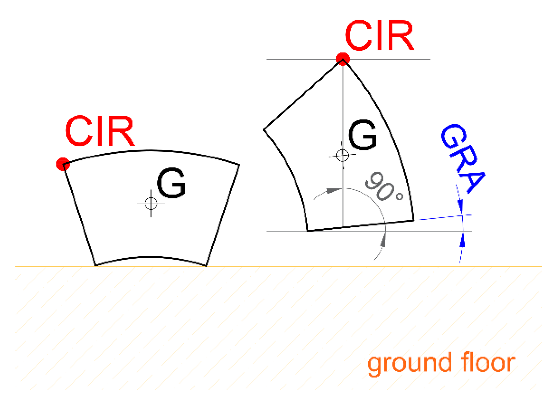
Figure 2c). Based on this theory, a block of the HLA finds a stable position in the space when its Center of Instant Rotation (CIR) is vertically aligned with the centroid, according to
Figure 3. Consequently, the bottom surface inclines with respect to the horizontal of an angle, namely, Gravity Rotation Angle (GRA).
3. Design Procedure
This section aims to report a design-oriented model for the geometry of the HLA. In the absence of external force, a suspended body reaches a stable equilibrium depending on the gravity force. The rotation can be defined by the GRA, which strongly correlates with the aspect ratio (length over width) of the body itself. For this reason, the relationship between GRA and
lm/s was investigated, and results are reported in
Figure 4, where
lm is the length of the middle line of each block, and s is the width of the block. Demonstrably, when an annular section segment is lifted up, as illustrated in
Figure 4, the GRA is the same as the angle reached by an Equivalent Rectangle (ER). The segment connecting the CIR and the intercept with the horizontal (passing through G)—
b—is the first side of the ER. The segment connecting the intercept of the horizontal axis with the normal line to the free face of the block, passing through CIR—
h—is the second side of the ER.
Given the nomenclature illustrated in
Figure 5, the design procedure in
Figure 6 can be implemented. The goal is to define the optimal aspect ratio so that all the blocks of the HLA are in contact when the arch is completely lifted. In this way, potential defects due to the positioning of the HLA are prevented. In fact, in the case of the wrong aspect ratio of the blocks, especially the terminal ones, unwanted movement of the HLA can be expected during the positioning of the support-devoted structure (e.g., buttresses).
The steps for application of the proposed model are as follows:
Definition of the inputs. In particular, the geometry of the arched element, the mechanical characteristics of the substrate, and the mechanical and geometric characteristics of the FRP material.
Determination of the effective bond length, led, for detachment or peeling. The weight of the half arch has to be considered as a debonding force.
Calculation of the geometric parameters, such as:
- I.
Impose according to ;
- II.
;
- III.
;
- IV.
according to
Figure 4.
Verification of the angles. If GRA≤α, the verification is satisfied, and then the input geometry is valid for the purposes of the construction technique. If not, one of the following solutions should be chosen:
- a.
Impose and determine
- b.
Calculate a new aspect ratio by
- c
Impose
Calculation of the geometric characteristics related to the final configuration:
- I.
Number of blocks, (odd and integer number);
- II.
;
- III.
;
- IV.
.
In other words:
Solution a consists of decreasing the number of blocks.
Solution b consists of reducing the arch thickness.
Solution c consists of changing the global shape of the arch.
Combined solutions are also valid.
Alternatively, the use of advanced numerical methods can be considered for the assessment of such structures, e.g., in [
23,
24,
25,
26].
4. Prototype
According to the model proposed in
Figure 6, a combined solution between b and c was assumed, as illustrated in
Figure 7, in order to build a first experimental prototype. In fact, a total of nine blocks (I–IX) and eight hinges (1–8) were necessary to reach a semi-circle shape. In particular, seven blocks were identical (i.e., II–VIII) with an extrados length equal to 328 mm from α ≥ 33° (solution c), while two base blocks (I and IX) were almost double-length (i.e., 657 mm) according to solution b. Both the thickness and the width of the arch were 150 mm, and the total span was 2000 mm long.
A local stone, namely, Leccese stone, with a mass density equal to ~1700 kg/m
3, was used. The trust-line method was used in order to check the stability of the proposed curvature for the prototype, as mentioned in the Introduction section, according to [
17,
18]. The shape of the prototype was optimal, considering that the transversal cross-sections were completely compressed (trust-line entirely falls within the central core of inertia of the arch cross-section). It is remarkable to note that the proposed construction method is valid for any curvature of the arch (e.g., round, pointed, elliptical, lancet, segmental, rampant, Tudor, etc.). The stone’s compressive strength was estimated experimentally equal to 12.03 ± 1.25 MPa, according to ASTM C170/C170M-17 [
27]. The blocks were cut by using CAM (Computer-Aided Manufacturing) waterjet technology suitable for stone cutting. As a consequence, the control of the geometrical dimensions, including the design curvature, was very sharp.
First, the extrados of the blocks was cleaned with compressed air to eliminate surface dust, and then it was prepared with a film of epoxy primer. Afterward, the blocks were joined by gluing a carbon sheet (150 × 3600 mm
2) on the extrados through an epoxy-based matrix. The main properties of the Carbon-FRP (CFRP) are reported in
Table 1, as tested according to ASTM D7565/D7565M-10 [
28]. The hinge in between two side-by-side blocks was obtained by using the butyl tape (see
Figure 1 and
Figure 8) for a length of 10 mm and a width of 150 mm (arch width), avoiding the bond between the FRP and the substrate.
5. Test Setup and Instrumentation
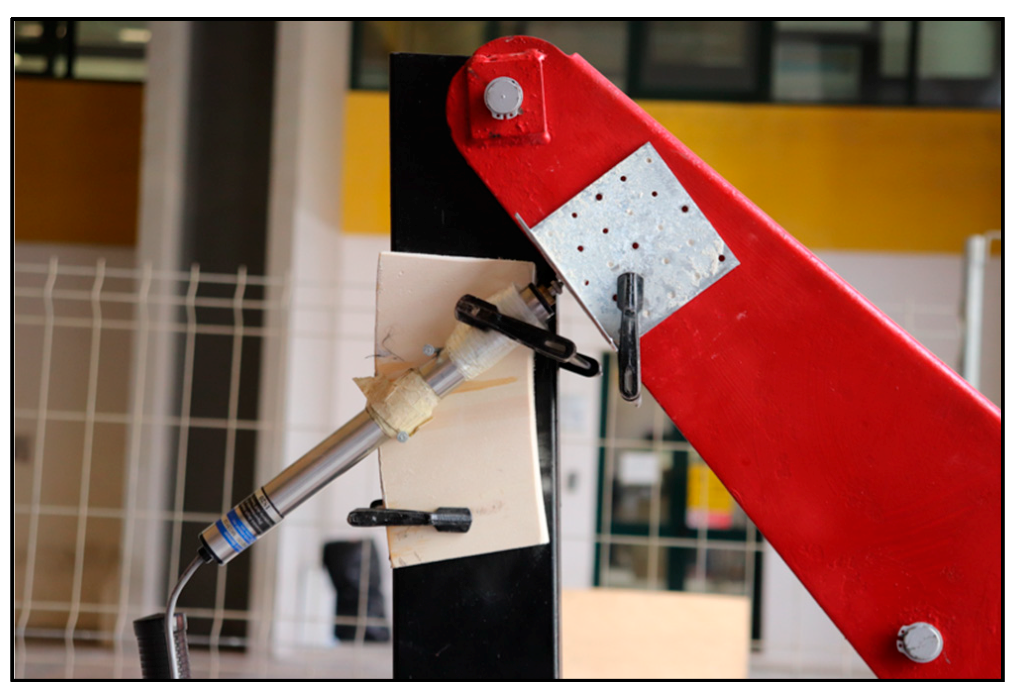
The prototype was instrumented, and the measuring tools are illustrated in
Figure 9. A tower crane was connected to the key-block by means of a harness. The arm of the tower crane was able to rotate. A Linear Variable Differential Transformer (LVDT) was oriented perpendicularly to the arm in order to measure the rotation, which is rigidly correlated with the lifting of the key-block in linear proportion (see
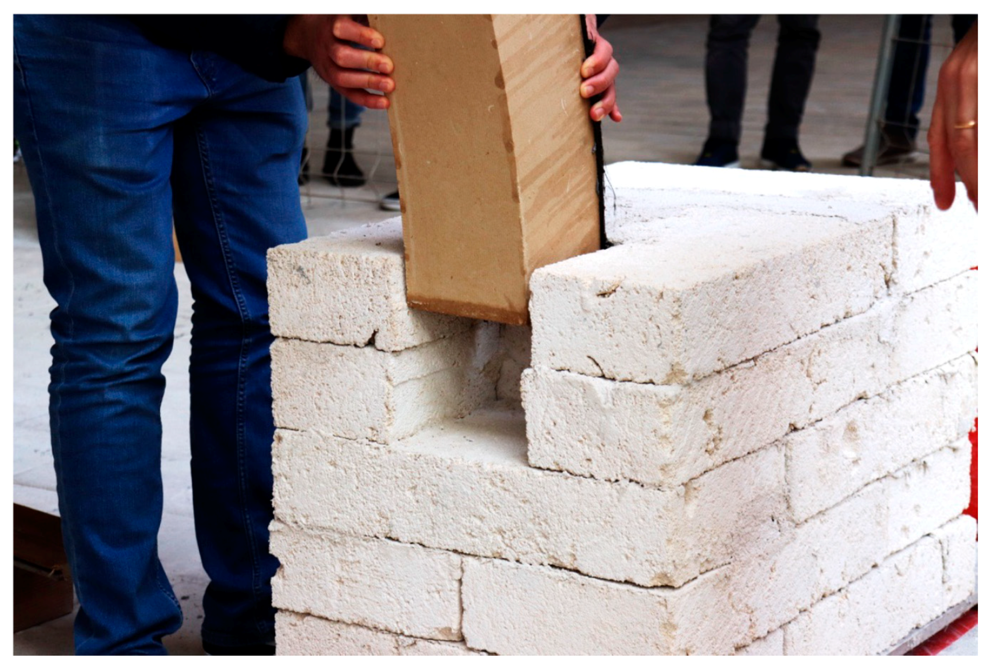
Figure 10). Moreover, eight strain gauges (SGs) were applied to the CFRP in the proximity of the hinges (SG1–SG8). The LVDT and the SGs were connected to a data acquisition control unit. Finally, three cameras filmed the lifting from 0°, 45°, and 90° orientations with respect to the normal-line of the key-block. In front of the HLA, a couple of Tuff-masonry buttresses, with dimensions of 750 × 750 × 500 mm and housing of 150 × 150 × 300 mm, were placed (see
Figure 9). The lifting was manually performed by ensuring that the end of the arm of the tower crane remained vertically aligned with the key-block. Four instances of the lifting procedure are illustrated in
Figure 11a–d and further photos are provided in
Figure A1,
Figure A2,
Figure A3,
Figure A4,
Figure A5,
Figure A6 and
Figure A7 (see
Appendix A). It is evident that the hinges acted properly while allowing the rotation of the adjacent blocks, which were in contact when fully lifted. The geometry of the arch assumed the designed shape when the end blocks were fully rotated. Once the lifting was completed, all of the blocks were visibly in contact. In this sense, the analytical procedure reported in
Figure 6 was validated. Finally, the HLA was positioned on the buttresses (see
Figure 12). The obtained prototype evidenced the reliability of the proposed construction technique. The housings constrained both the horizontal displacement and the out-of-plane rotation of the arch. Further photographic evidence is reported in the
Appendix A.
7. Conclusions
The present paper presents a new constructive technology for curved masonry elements by using externally bonded FRP materials instead of traditional temporary scaffolds (namely, centering). A calculation model for the design of the proposed technique was developed and illustrated. Furthermore, an experimental prototype was built using limestone blocks. As a consequence of the obtained results, the following conclusions are reported in order to highlight the advantages of the proposed technique:
It is possible to build arches in situ by using FRP materials and lifting techniques, avoiding the use of traditional methods, such as temporary scaffolding;
The proposed construction technology has several advantages in terms of construction time-saving, ease of installation, safety, lower construction site costs, and the possibility of constructing masonry arches even at high altitudes. In addition to this, the seismic capacity of the arch is increased thanks to the presence of the FRP;
The calculation model for the design of the construction technique has the advantage of being applicable to any curved structure;
The experimental prototype confirmed the validity of the analytical procedure and the fast and inexpensive application of the technique.
On the other hand, the bond between the FRP and the substrate should be carefully assessed, requiring skilled expertise. Other limitations could be found by means of further experimental investigations. In this perspective, possible future research developments are proposed, such as:
Further optimizations regarding the construction and installation of arches using the lifting technique, with particular attention to the required materials and tools;
Application of the technique to curved glulam timber structures as well;
Application to 3D structures such as vaults and domes;
Development of software applications for the design;
Mechanical testing under different load conditions, as typically performed for FRP-strengthened masonry arches (in progress).


