Review

Recent Progress in Hybrid Solar Cells Based on Solution-Processed Organic and Semiconductor Nanocrystal: Perspectives on Device Design

1
School of Materials Science and Engineering, South China University of Technology, Guangzhou 510640, China
2
Institute of Polymer Optoelectronic Materials & Devices, State Key Laboratory of Luminescent Materials & Devices, South China University of Technology, Guangzhou 510640, China
3
Guangdong Provincial Key Laboratory of Optical Fiber Sensing and Communications, Guangzhou Key Laboratory of Vacuum Coating Technologies and New Energy Materials, Siyuan Laboratory, Department of Physics, Jinan University, Guangzhou 510632, China
*
Authors to whom correspondence should be addressed.
Appl. Sci. 2020, 10(12), 4285; https://doi.org/10.3390/app10124285
Submission received: 31 May 2020 / Revised: 14 June 2020 / Accepted: 16 June 2020 / Published: 22 June 2020
(This article belongs to the Special Issue Synthesis, Characterization and Application of Hybrid Composites)

Abstract

:
Solution-processed hybrid solar cells have been well developed in the last twenty years due to the advantages of low cost, low material-consuming and simple fabricating technology. However, the performance, stability and film quality of hybrid solar cells need to be further improved for future commercial application (with a lifetime up to 20 years and power conversion efficiency higher than 15%). By combining the merits of organic polymers and nanocrystals (NC), the reasonable design of interface engineering and device architecture, the performance coupled with stability of hybrid solar cells can be significantly improved. This review gives a brief conclusive introduction to the progress on solution-processed organic/inorganic semiconductor hybrid solar cells, including a summary of the development of hybrid solar cells in recent years, the strategy of hybrid solar cells with different structures and the incorporation of new organic hole transport materials with new insight into device processing for high efficiency. This paper also puts forward some suggestions and guidance for the future development of high-performance NC-based photovoltaics.

1. Introduction

The usage of semiconductor nanocrystals (NCs) as the light harvesting materials in thin film solar cells has attracted intense research over a period of nearly two decades [1,2,3,4,5,6]. The solution-processed hybrid solar cells (HSCs) are recently developed and offer the potential advantages of low cost, low materials consumption, simple fabrication process, etc. Among all kinds of the NCs in solution-processed HSCs, CdSe [7], CdTe [8], ZnO [9], TiO2 [10] and PbS [11] have been well used due to their appropriate bandgap, stability and high optical absorption coefficient. In general, solution-processed HSCs consist of a transparent conducting metallic oxide layer (such as ITO, FTO or AZO), an electron transfer (ETL), a photoactive layer, a hole transfer layer (HTL) and a back contact electrode layer. To prepare HSCs, a polymer and NCs are firstly dispersed into a solvent such as octane, toluene, alcohol, chloroform or water with typical concentrations around 10 mg/mL [12,13]. The hybrid solution is then deposited on a substrate by spin-casting or printing. The photovoltaic performance of HSCs can be easily adjusted at the atomic or molecular level. Compared to organic solar cells (OSCs), the HSC emerged very late and the progress has been relatively slow, which is mainly due to the compatibility issue between organic polymers and NCs. For example, the solubility of the two materials in some solvents is quite distinctive due to the large difference of polarity, and the operation mechanism or physical essence for organic/NC junctions is complex and still controversial [14,15]. There are many strategies to improve the HSC properties, in which the device architecture of the HSC shows a significant effect on the efficiency of the HSC. In this review, we report the advances in hybrid solar cells based on the solution-processed semiconductor NC/polymer and focus particularly on the optimized device design for improving HSC performance. Here, we begin with introducing the fabrication of HSCs by using a single bulk heterojunction (BHJ) active layer. Then, the fundamentals of hybrid bulk heterojunction active layers are depicted. The HSCs with multi-photoactive layers and complex structure are then presented. The hole/electron transfer equilibrium is also a key factor for improving NC solar cell performance. Here, we emphasize to address the numerous strategies using organic materials as hole/electron transfer layers for the efficient collection of holes and electrons. To extend the range of the spectrum response for HSCs, a tandem structure is preferred to further improve the device performance. In the end, we will emphasize the challenges and future prospects in the architecture design of HSCs towards ~15% power conversion efficiency (PCE) aiming for commercial application.

2. Hybrid BHJ Solar Cells with a Large Bandgap Semiconductor NC as an Acceptor

The active layer of HSCs is an interpenetrating network structure in the early time, which is similar to OSCs [16]. It is well known that the OSCs consist of a BHJ active layer which includes a polymer as a donor and (6,6)-phenyl-C61-butyric acid methyl ester (PCBM) as an acceptor [17]. The drawback in this structure is the relative low mobility of electron acceptor PCBM that may affect electron transfer and collection in the OSCs. By replacing PCBM with semiconductor NCs as the acceptor, the polymer NC hybrid thin film may combine the merits of high light absorbance of organic polymers and high electron mobility of the stable semiconductor NC, which is promising for achieving inexpensive, stable and high-performance solar cells. In the early work of HSCs, Alivisatos et al., for the first time, reported a novel HSC with a device configuration of ITO/poly (3-hexylthiophene) (P3HT): CdSe NC/Al by solution processing [18]. Right here, electrons transferred along CdSe nanorods while holes were transported in the polymer. Figure 1a–c shows the structure of regioregular P3HT, energy diagram of the polymer and NCs and device structure. Photogenerated electrons are transferred from the conduction band of the polymer into the conduction band of the NC while holes from NC to polymer. It was found that the CdSe NC and P3HT in the blend film have a complementary absorption property in the visible spectrum. In addition, by altering the diameter of CdSe NCs, the onset of the absorption spectrum can be tuned in a large range. By carefully controlling both the diameter and length of CdSe NCs, a PCE of 1.7% was obtained in a champion device. The experimental results indicate that the length of nanorods has a bigger effect on the PCE of HSCs than the diameter of NCs. The onset of the spectrum response was extended up to ~720 nm by improving the diameter of NCs.
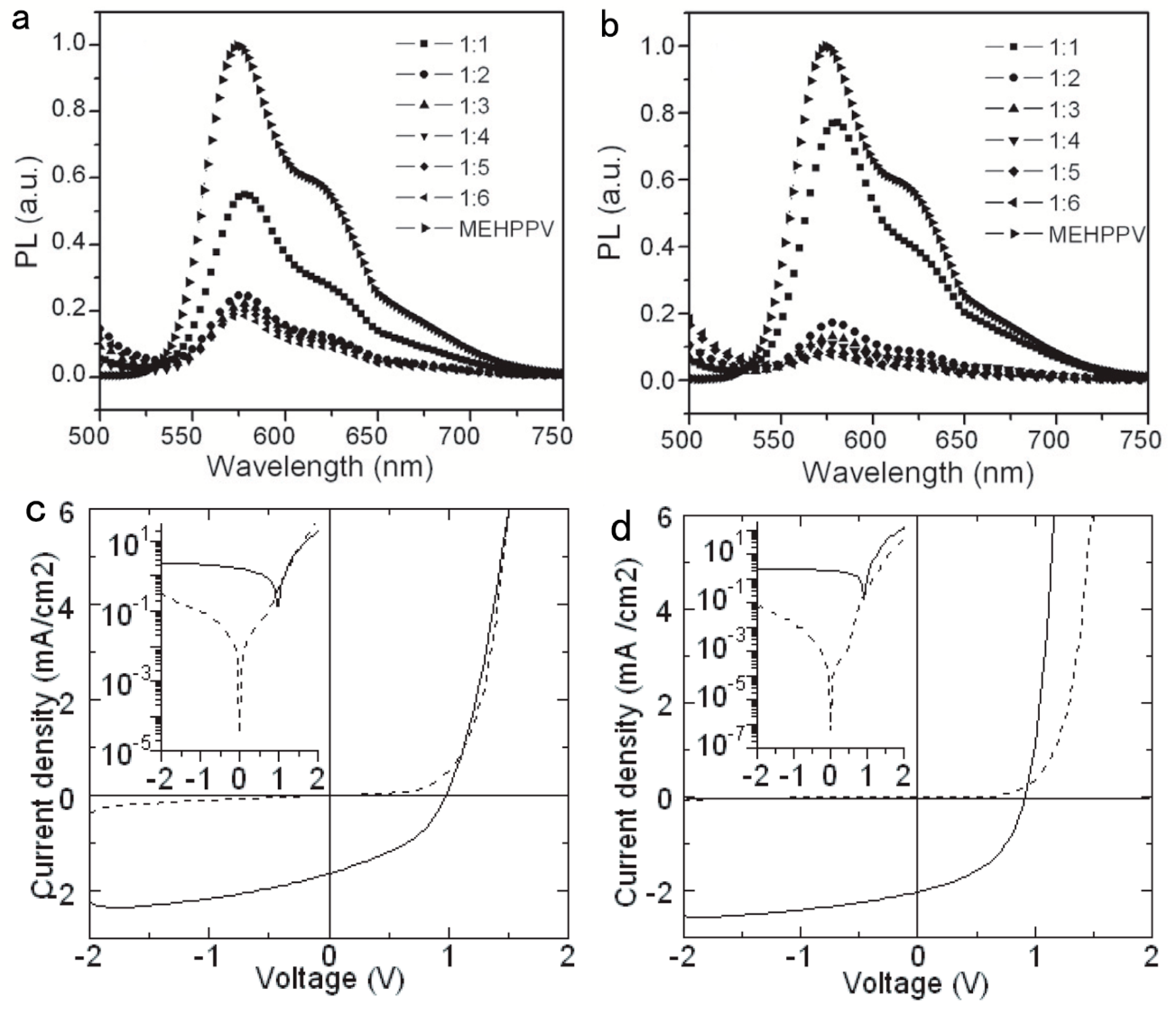
Couderc et al. [19] adopted the ultrafast transient spectroscopy to investigate the charge transfer (CT) dynamics between the polymer and NCs of the hybrid film. Through systematically analyzing the bleaching signal of CdSe NCs, the electron transfer was found to occur in a very fast way (less than 65 fs). The morphology of CdSe NCs has a significant effect on HSC performance. Sun et al. [20] found that the HSC processed from the mixture of multi-armed CdSe NCs and a traditional polymer P3HT showed enhanced properties than the device from nanorod/polymer blends, which was attributed to the improved electron extraction since CdSe tetrapods with four arms can facilitate the electron transfer vertical to the plane of the active layer. When the polymer P3HT was replaced by poly(p-phenylenvinylene) derivative (OC1C10-PPV), [21] and a solvent of 1,2,4-trichlorobenzene with a high boiling point (up to 200 °C), instead of chloroform used to prepare the HSC, a high PCE of 2.8% was obtained. Subsequently, the crystalline structure and the solubility of CdSe NCs were found to greatly affect the HSC performance [22,23]. Han et al. [22] developed a new receipt for the fabrication of spherical CdS NCs using cadmium carboxyl as the Cd precursor. From Figure 2a,b, the photoluminescence (PL) intensity of hybrid blends decays linearly with the increase of CdSe NC content, which is irrespective to the CdSe NC synthesis method. The HSC based on MEH-PPV: CdSe NC blend film showed improved efficiency when post-annealing at 180 °C was carried out (Figure 2c,d).
In most cases, CdSe NCs are prepared by the solvothermal method. Long-chain organic ligands such as alky acid, alkyl phosphoric acid or trioctylphosphine oxide (TOPO) are used to stabilize the NCs and prevent their aggregation [24,25,26,27,28]. However, the side chains of polymers (usually alkyl chains) cannot cap on the surface of NCs, which makes the separation of the organic/inorganic phase uncontrollable in the hybrid active layer and hinders the transfer of charges between the NC and polymer and thus reduces device performance. To address this problem, Liu et al. [29] fabricated P3HT with different functional groups that can easily control the morphology of polymer/CdSe NCs. Figure 3a shows the synthesis process of P3HT with a –NH2 functional group. When blended with an NC acceptor, the amino end group of the P3HT donor caps on the surface of the NC and forms intimate nanocomposites with a favorable morphology. The HSC shows a significantly higher PCE than the control device (Figure 3b). More importantly, the highest efficiency occurred at lower concentrations of CdSe NCs, which is mainly determined by the high degree of homogeneity of hybrid blend layers.
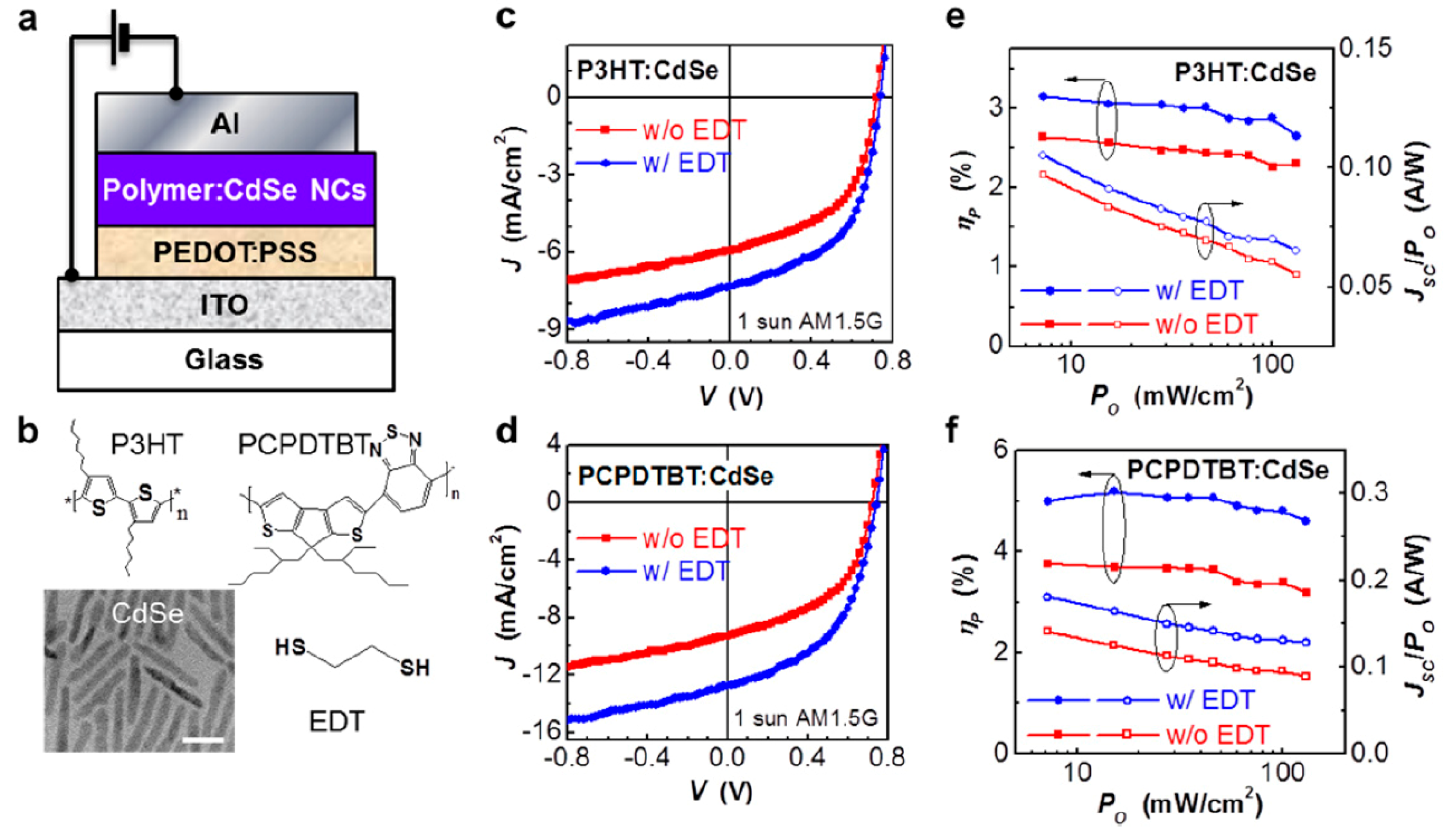
An alternative way to improve the quality of the HSC active layer is to eliminate the insulated ligands (such as oleic acid) on the CdSe NC, which will reduce the interface recombination between the NC and polymer, and improve the carriers’ collecting ratio. In recent years, solution-processed PbS colloidal quantum dot (CQD) solar cells have attracted much attention and excellent achievement has been obtained (with PCEs exceeding 12%), which is mainly attributed to the ligand chemistry engineering. The insulated ligands oleic acid (OA) can be replaced by 1,2-ethanedithiol (EDT), mercaptopropionic acid (MPA), NH4I, etc. [30,31,32,33]. Inspired by these fruitful works, Ren et al. [34] demonstrated a facile method to fabricate nanoscale morphology of P3HT nanowires (NWs) and CdS NC blends adopting the ligand exchange method and solvent-assisted chemical grafting. It was found that an interpenetrating BHJ network was formed in the blends, which increased the carriers’ separating and collecting ratios, leading to efficient PCE. The HSC with a configuration of ITO/poly(3,4-ethylenedioxythiophene):poly(styrenesulfonate) (PEDOT:PSS)/P3HT NW:CdS/bathocuproine (BCP)/Mg:Ag delivered an energy conversion efficiency exceeding 4%. It should be noted that P3HT or PPV was widely used as the donor material for HSCs in early works [19,22,29]. Unfortunately, the onset of the spectrum response for these materials (with bandgaps exceeding 1.9 eV) was below 650 nm, which significantly reduced photon absorption in the longer wavelengths and thus rendered the short-circuit current density (Jsc) of HSCs. Poly [2,6-(4,4-bis-(2-ethylhexyl)-4H-cyclopenta [2,1-b;3,4-b0]-dithiophene)-alt-4,7-(2,1,3-benzothiadiazole)](PCPDTBT), a conjugated polymer with a low bandgap, has been widely used in OSCs [35]. PCPDTBT used as a donor in HSCs should expand the spectrum responsibility into the near-infrared field and thus high Jsc is expected. Moreover, in order to adjust the interface morphology among the blend of PCPDTBT/CdSe NCs, different substituents (–NH2, –OCH3, –CH3, –F, –(CF3)2, –NO2) have been developed to replace the terminal group of the benzenethiols (BTs) [36]. It is important to select the ligand unit with an appropriate molecular dipole as it has an intense effect on the molecular and electronic framework at the polymer/NC boundary and subsequently on HSC properties. A maximum efficiency of 4.0% for HSCs was obtained when 4-uorobenzenethiol was selected to make the ligand exchange. Zhou et al. [37] developed a post EDT treatment strategy for hybrid blend film using a device architecture of ITO/PEDOT:PSS/P3HT:CdSe NCs/Al (Figure 4a,b). After EDT treatment, from the Fourier transform infrared (FTIR) measurement results, one could see that the absorption peaks for the -CH3, P-O and P=O groups were significantly decreased, which implies the TOPO or TDPA can be effectively removed by ligand exchange.

3. Hybrid Bulk Heterojunction Solar Cells Using Low Bandgap Nanocrystals

HSCs based on polymer: CdSe (or other wide bandgap semiconductors such as ZnO, CdS and TiO2 [38,39]) NC BHJ have been well explored, and PCEs up to 4% have been obtained by optimizing hybrid layer morphology and ligand engineering. However, HSCs can only absorb visible light and the onset of the spectrum response is mainly determined by donor materials, which restrict HSCs for largely usage of long-wavelength infrared photons. Recently, PbS [40], PbSe [41] and PbSxSe1-x [42,43] alloy NCs have demonstrated potential application in low cost, highly efficient photovoltaic products as they contain special properties, for example, a size-tunable bandgap, high charge carrier mobility, multiple charge generation and solution processable ability. A PCE of 12% for PbS NC bulk homojunction photovoltaics has been certificated recently by surface ligand engineering and an optimized design of device structure [44]. By incorporating PbS or PbSe into HSCs, the efficient use of both short and long (>700 nm) wavelength photons was achieved [45]. In 2010, Noone et al. [46] described new HSCs containing a mixture of colloidal PbS NCs and donor polymers including poly(2,3-didecyl-quinoxaline-5,8-diyl-alt-N-octyldithieno[3,2-b:2′,3′-d] pyrrole) (PDTPQx), PDTPBT and P3HT. It was found that when the polymer PDTPQx was employed, the PCE was 10–100 times higher than that based on traditional polymers of P3HT or PDTPBT. It was confirmed that the PDTPQx:PbS NC HSC behaved as the real bulk heterojunction rather than as other junctions such as Schottky diodes.
Although the early ligand exchange method (for example, the alky acid ligands of PbS NCs were substituted by amine ligands before mixing) can improve HSC performance, the butyl amine ligand still affects the polymer matrix during the film deposition. Seo et al. [47] demonstrated a simple method to improve the performance of HSCs using PbS NCs and PDTPBT as the blends. In this case, the blend film was treated by direct post-deposition ligand exchange using 1,2-ethanedithiol (EDT). The OA ligand was selectively replaced by EDT without affecting the polymer matrix. A PCE as high as 3.78% was achieved after further optimizing the device structure by inserting an ETL TiO2 (device structure: ITO/PEDOT:PSS/PDTPBT:PbS EDT/TiO2/LiF/Al). In truth, the observed interparticle spacing is reduced after the alky acid ligand is substituted by EDT or MPA ligands (~4.37 nm for OA ligands and ~3.36 nm for EDT or MPA ligands), which has been confirmed in the previous work [48]. The –SH can be tightly bonded to the surface of the PbS NC and replace the OA ligand, which can reduce the distance between neighboring NCs and decrease interface recombination. Moreover, Piliego et al. [49] demonstrated that the charge separation efficiency was nearly the same as the organic-organic blends for the PbS-polymer hybrid blends. The low performance of HSCs is greatly affected by worse morphology and more traps in the hybrid blends. Most recently, Lu et al. [50] used iodidum such as lead iodide (PbI2) and ammonium iodide (NH4I) coupled with n-butylamine to make ligands exchange for PbS NCs. HSCs based on Si-PCPDTBT and NH4I- or PbI-capped PbS NCs were fabricated without further post ligand exchange. From the results presented by the time-resolved PL spectroscopy, one could see that the PbI2-exchanged HSC showed higher energy or a charge transfer process than the NH4I-exchanged HSC. A PCE of 4.8% was achieved for the HSC with the PbI2-exchanged PbS acceptor, ranking among the best value ever presented for polymer-PbS NC BHJ solar cells.

4. HSC with More Active Layers

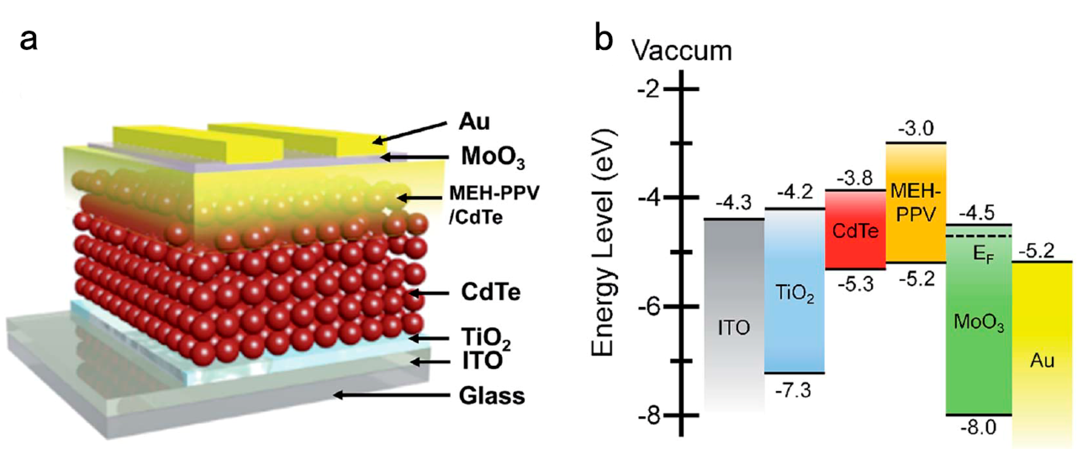
In the case of the BHJ photovoltaic device, the blend mixture includes a conjugated polymer and a semiconductor NC. The carrier recombination between the hybrid layer and the contact electrode is serious, which renders the performance of the HSC. It was confirmed that the self-assembly property of the active solution in the coating process significantly affects the phase separation of the dried hybrid layer, which is important for the carrier departure and charge migrate [51,52]. As for the polymer/fullerene blend solar cells, it is well known that the donor/acceptor phase separation in the vertical distribution in the polymer/fullerene blend film is also critical to device performance [53,54]. Therefore, an optimized device architecture for HSCs may consist of multi-film such as donor: acceptor (BHJ)-donor-acceptor structure (D:A-D-A) for optimizing interface engineering. With this strategy, the charge recombination is reduced, which has been demonstrated in small molecule OSCs [55,56]. For HSCs, Liu et al. [57] designed a device with a configuration of ITO/TiO2/CdTe/MEH-PPV:CdTe/MoO3/Au based on aqueous-processed CdTe NCs and MEH-PPV. Figure 5a and Figure 5b show the schematic device structure and band alignment of semiconductor NCs and the polymer.
The ratio of MEH-PPV to CdTe in the mixture layer was found to affect the nanoscale morphology of hybrid blend film, which then impacts CT and transport. A PCE as high as 4.20% was attained by controlling the ratio of MEH-PPV: NCs in the blend film (the optimized weight ratio for MEH-PPV: CdTe is 1:12) and annealing temperature (the optimized temperature is 315 °C). Later on, the PCE was further improved to 4.32% when the MEH-PPV was replaced by another polymer P3HT [58]. To enhance the internal quantum efficiency and extend the range of the depletion field, an HSC with both sides bulk heterojunction (BHJ) (device architecture ITO/TiO2/CdTe:TiO2/CdTe/PPV:CdTe/MoO3/Au) was recently reported by Jin et al. [59]. They found that employing different acceptors with more active layers can simultaneously suppress the interface recombination and promote the carrier extraction in the HSC. Benefiting from the advantages of increased carrier collection and lifetime, a PCE up to 6% was obtained in a champion device. Following this, this research group selected ZnO NCs and sol-gel ZnO as an acceptor/ETL to build an HSC with a device architecture of ITO/ZnO/CdTe:ZnO NC/CdTe/PPV:CdTe/MoO3/Au [60]. A high PCE of 6.51% was achieved, which was among the highest PCEs already reported for aqueous-processed CdTe NC HSCs. In the field of PbS NC HSCs, the main reason for high device properties in these cases is mainly attributed to the exchange ligands, which reduce the defect density by passivating the bulk and interface states. It is noted that the PbS NCs become insoluble in most organic solvent after ligand-exchange, which prevents the dissolvement of the polymer: PbS NC layer when the PbS NC layer is deposited on the hybrid blend. Therefore, an optimized structure with the configuration of D-D:A-A can be realized for PbS NC HSCs. Inspired by efficient small molecule OSC design [55], Liu et al. [61] developed a D-D:A-A HSC structure of ITO/PEDOT/DDTPBT: NC/NC/LiF/Al. A PCE as high as 5.50% coupled with improved FF was achieved in this HSC, which is mainly owed to the outstanding properties of the PbSxSe1-x alloy NCs and the optimized device structure for efficient carrier separation and collecting. The band alignment of the polymer and PbS NCs was also found to be critical for charge separation. In the case of HSCs with the configuration of ITO/PEDOT–PSS/polymer: PbS/PbS/LiF/Al, a maximum PCE was obtained when using PDBT as the donor materials in the blend mixture [62]. Although various strategies for HSCs have been studied to improve the PCE by exploiting the merits of conjugated polymer and semiconductor materials, the PCE of these HSCs is still far below 10%; the value is remarkably lower than pure PbS NCs or OSCs. This is mainly attributed to the poor charge transfer and carrier extraction efficiencies in the hybrid blend film. Most recently, Baek et al. [63] developed a new HSC with the device structure of ITO/ZnO/PbS NC/PBDTTT-E-T: 2,2’-((2Z,2’Z)-((5,5’-(4,4,9,9-tetrakis(4-hexylphenyl)-4,9-dihydros-indaceno[1,2-b:5,6-b’]dithiophene-2,7-diyl)bis(4-((2-ethylhexyl)-oxy)thiophene-5,2-diyl))bis(methanylylidene))bis(3-oxo-2,3-dihydro-1H-indene-2,1-diylidene))dimalononitrile (IEICO)/MoO3/Ag. There are two active layers in this device configuration, viz. PbS NCs and polymer/SM blend film. The usage of small-molecule acceptors instead of NCs increases the efficiency reported for all solution-processed organic/inorganic NC HSCs.

5. HSCs Using Organic Materials as the HTL

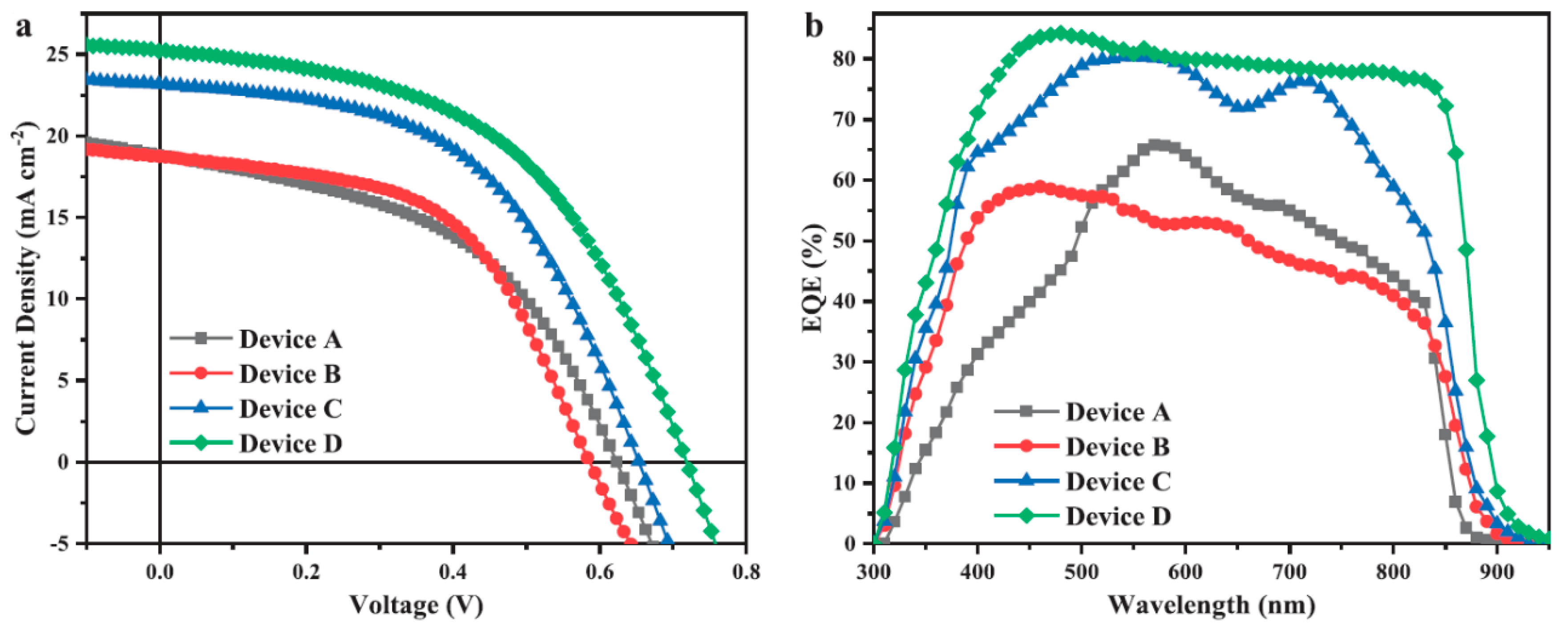
For NC solar cells, the carrier recombination between the active layer and the contact electrode is serious, which renders the weak collection of carriers. For example, the CdTe thin film has a high work function (up to 5.3 eV) due to its self-compensation effects [64], which makes it difficult to attain ohmic contact between CdTe NC thin film and a metal electrode. There are several ways to obtain ohmic contact for CdTe-based solar cells with inverted structure. Among which, introducing a low cost and stable HTL for reducing carriers recombining is preferred. It is well known that MoOx [65], V2O5 [66], NiO [67], WO3 [68] and other metal-organic dielectric materials [69,70] are widely used as HTLs in CdTe thin film solar cells and improved performance is usually obtained. However, researchers have found that these metal oxide materials are not stable when exposed in ambient conditions and the energy levels are difficult to be changed, which is not preferred for commercial application. On the contrary, there are many advantages for organic hole transport materials with a high HOMO level, such as being stable, low energy-consuming and they can be fabricated by a solution process. Recently, Wang [71] et al. developed PEDOT: PSS as an HTL between CdTe thin film and a contact electrode, and the device showed improved efficiency compared to the control devices. Spiro-OMeTAD(2,2,7,7-tetrakis(N,N-di-4-methoxyphenylamino)-9,9-spirobitluorene), as an important hole transfer material, has been applied successfully in perovskite solar cells, which is also preferred for NC solar cells as the high work function (~5.2 eV) [72]. Based on potential change results presented by Kelvin probe microscopy between Spiro and the CdTe NC film, it was found that a dipole field is formed between CdTe NC and HTL, which strengthens the build-in electric field and increases the NC device’s performance. However, like many metallic oxides, PEDOT: PSS or Spiro-OMeTAD is not stable under wet environments. Guo [73] and coworkers, for the first time, incorporated a crosslinkable conjugated polymer as an HTL for decreasing carrier recombination in the interface of the NC thin film and contact metal. Compared to other organic HTLs, crosslinkable conjugated polymers are very stable after the crosslinking reaction, and can be adhered to the NC surface by forming N-Cd bonds. Moreover, this material has high carrier mobility and easy tunability of energy levels by molecular design. In this case, a poly(diphenylsilane-co-4-vinyltriphenylamine) HTL is deposited on the CdTe film and forms a Cd-N covalent bond, which reduces the interface trap state and carrier recombination. More importantly, a dipole layer is formed between CdTe NC film and the HTL, which facilitates holes’ transport with a small barrier and improves carriers’ collecting efficiency. As high as 8.34% PCE has been obtained in NC solar cells with a Si-TPA interlayer, which is significantly higher than the controlled device or device with PEDOT:PSS or PVK as an HTL. In addition, it was demonstrated that CdTe solar cells with CdSe as the n type partner may be subjected to low Voc owing to a large electron injection barrier and interface recombination in metal oxide/CdSexTe1-x alloys [74]. By incorporating a CdS/CdSe NC double ETL and TPA HTL, the interface recombination was decreased and high Voc expected [75]. The device structure and preparing process are presented in Figure 6. These two aspects’ optimization led to reduced interface trap-assisted recombination both in the ZnO/CdS and CdTe/contact electrode. As shown in Figure 7, a very high PCE of 9.2% was attained by simultaneously optimizing the ETL and HTL of the HSC. Besides, it is noted that the EQE spectrum of the optimized device showed a high EQE value from 400 to 900 nm, which is significantly higher than other control devices. The high performance obtained in this case was recorded for all CdTe NC HSCs with inverted structure.

6. HSCs with Tandem Structure

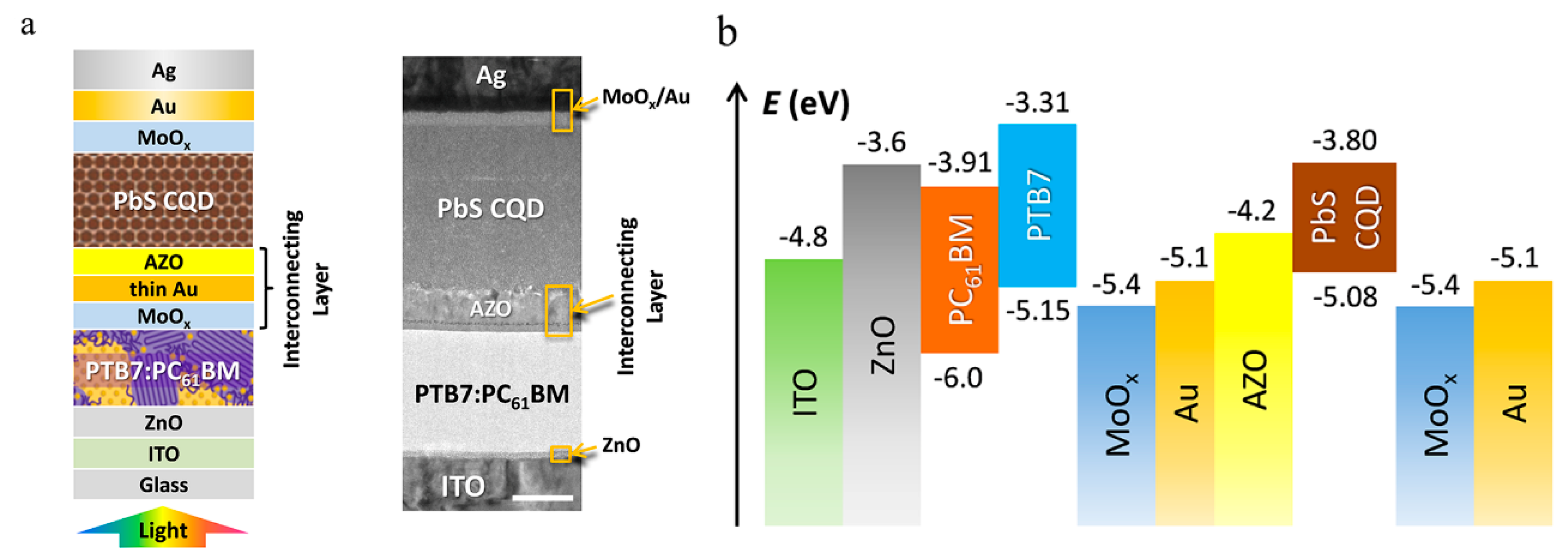
With the rapid development of molecular and device design, up to 18% efficiency has been realized in single junction OSCs [76]. However, the further improvement of single junction solar cell performance is limited, and thus double, triple or more junction solar cells should be carried out to improve the HSC performance [77,78,79]. For solar cells with tandem structures, broader spectrum photons can be harvested after using different bandgapsvactive materials. Organic and some NCs such as PbS have similar fabricating technology, and low-cost, light-weight solar modules can be realized using the same coating method. Compared to organic thin film, PbS NC layers benefit from a tunable bandgap by adjusting the size of PbS quantum dots, which is appropriate for tandem cell design. In 2014, Speirs and coworkers [80], for the first time, reported a new tandem HSC employing PbS NCs as the front sub-cell while a P3HT: PCBM blend was the bottom cell (device structure: ITO/PbS/WO3/Al/P3HT:PCBM/Al), which allowed the usage of sunlight from ultraviolet to near-infrared. However, only a 1.8% PCE was attained for this device, which shows also lower performance than the PbS NC or P3HT:PCBM solar cells. The main reason for low efficiency originates from the interface recombination and inadequate fabricating parameter optimization for each single junction. Later on, Kim et al. [81] developed a different device design consisting of PbS NCs as the bottom cell and a polymer (with large bandgap): fullerene blend as the top cell (device structure: FTO/TiO2/PbS NC/MoOx/ZnO/PFN/polymer:fullerene/MoOx/Ag). The HSC-based tandem structure delivered a high Voc (1.3 V) and PCE greater than 5% after optimizing the tunnel junction layer and individual organic/inorganic cells. The effective connection of two single sub-cells in hybrid tandem solar cells is very important for decreasing interface recombination and internal losses. It was found that when MoOx/Au/ZnO was selected as the interface recombination layer in the hybrid tandem cell with a device architecture of ITO/AZO/PbS/MoO3/Au/PFN/PCBM:PDPP3T/MoO3/Ag, an 8.3% PCE was obtained after optimizing the optical and electrical properties of each sub-cell [82]. However, in the previous reports, one noteworthy limitation was the inaccurate arrangement of the PbS NC (with low bandgap) layer as the front cell, which limited the light harvested and prevented the tandem cells to create more photocurrent. The main reason for this structure design is the incompatibility of the PbS NC solution to organic bulk heterojunction layer [83,84]. Secondly, in order to improve the PbS NC film quality, ligand (such as MPA or EDT) exchange must be taken out to eliminate trap states, which cause additional damage of underlayers [85]. To overcome these challenges, PbS NC ink utilizes hexane and the deposition of PbS NCs is simplified by eliminating the many steps required for PbS NC layer deposition. Figure 8a presents the device structure of an HSC with a tandem configuration. The organic PTB7:PCBM blend device acts as the front cell while PbS NCs act as the bottom cell. Figure 8b shows the band alignment of the hybrid tandem solar cell. Here, an ultrathin (0.5 nm) Au film was inserted between the AZO and MoOx layer, as the effective recombination centers to decrease the collection of photo-generated carriers in the active layers. After optimizing device fabricating parameters, the tandem solar cell reached a high PCE of 9.4%.
Most recently, Aqoma et al. [86] presented a hybrid tandem cell in which organic BHJ worked as the back-cell collected the NIR photons while the CQD layer absorbed the visible light photons. This device with a configuration of ITO/ZnO/PbS/EDT-PbS/Au/ZnO/PTBT-Th:IEICO-4F/MoO3/Ag reinforced the photon-to-current conversion from visible to NIR wavelengths (from 350 to 1000 nm). A champion device achieved a PCE of 12.8% after optimizing the Jsc balance in conjunction with excellent series connection, which ranks among the highest PCE ever reported in PbS hybrid tandem solar cells.

7. Conclusions

The hybrid organic/inorganic NC solar cell is considered to be a promising candidate as a next generation photovoltaic product. Recent developments of organics and NCs for photovoltaic applications have been promoted including device design, interface engineering, new molecular design and synthesis, film processing techniques, ligands exchange technics, etc. These have enabled the solution-processed HSC to achieve a PCE of over 12%. The efficient HSC with all kinds of the device configurations reported in recent years are summarized in Table 1.
Compared to pure NCs or OSCs, HSCs exhibit several advantages such as combining the merits of high electron mobility of semiconductor NCs and high absorption coefficients of organic polymers, complementary light absorption spectra, the use of stable inorganic semiconductor NCs and high practicability of film fabrication based on solution processing. HSCs are expected to be applied in flexible and low-cost photovoltaic products in the future. There are several urgent issues to be handled to further improve the PCE and stability of HSCs. Firstly, it is critical to design or select an appropriate polymer to permit well band alignment with NCs for BHJ structure. Secondly, the interfacial junctions between the polymer HTL and NC layer should be studied deeply as the trap states in the interface could behave as non-radiative recombination centers. Thirdly, more junctions should be introduced into the HSC design to expand the spectrum response to 1,200–1,300 nm, for example, by using PbS quantum dots with a small bandgap (~1.0 eV) as bottom sub-cells for IR harvesting in the optimized device structure. Finally, the lifetime of HSCs has not been studied extensively. Compared to the commercial inorganic thin film photovoltaic module (~12% for amorphous silicon and ~19% for CdTe and CuInGaSe2 [87]), the PCE of HSCs (~13% for the best cells with a small area) needs to be further improved. Moreover, the stability of HSCs should be improved by materials purify, device design, interface passivation and device packing technology. Anyway, much attention should be paid to practical applications. With the development of HSCs, solution-processed HSCs must have a promising future for solar cell applications.

Author Contributions

D.Q., S.X. and W.X. searched and classified the literature; D.Q., S.X., L.H., W.X., X.L., Y.J., R.Y., M.F., W.L. and Y.P. wrote the paper. All authors have read and agreed to the published version of the manuscript.

Funding

This research received no external funding.

Acknowledgments

This work is financially supported by the National Natural Science Foundation of China (No. 21875075, 61774077, 61274062, 61775061), Guangdong Natural Science Fund (No. 2018A0303130041, No. 2018A0303130211), Guangzhou Science and Technology Plan Project (No. 201804010295), National Undergraduate Innovative and Entrepreneurial Training Program (No. 201910561011), the Key Projects of the Joint Fund of Basic and Applied Basic Research Fund of Guangdong Province (2019B1515120073) and the Fundamental Research Funds for the Central Universities for financial support.

Conflicts of Interest

The authors declare no conflict of interest.

References

  1. Kiani, A.; Sutherland, B.R.; Kim, Y.; Ouellette, O.; Levina, L.; Walters, G.; Dinh, C.T.; Liu, M.; Voznyy, O.; Lan, X.; et al. Single-step colloidal quantum dot films for infrared solar harvesting. Appl. Phys. Lett. 2016, 109, 183105. [Google Scholar] [CrossRef] [Green Version]
  2. Zeng, Q.; Chen, Z.; Zhao, Y.; Du, X.; Liu, F.; Jin, G.; Dong, F.; Zhang, H.; Yang, B. Aqueous-Processed inorganic thin-film solar cells based on CdSexTe1–x nanocrystals: The impact of composition on photovoltaic performance. ACS Appl. Mater. Interfaces 2015, 7, 2322–2323. [Google Scholar] [CrossRef] [PubMed]
  3. Beek, W.J.; Wienk, M.M.; Janssen, R.A. Efficient hybrid solar cells from zinc oxide nanoparticles and a conjugated polymer. Adv. Mater. 2004, 16, 1009–1013. [Google Scholar] [CrossRef]
  4. Arici, E.; Sariciftci, N.S.; Meissner, D. Hybrid solar cells based on nanoparticles of CuInS2 in organic matrices. Adv. Funct. Mater. 2003, 13, 165–171. [Google Scholar] [CrossRef]
  5. Arici, E.; Hoppe, H.; Schäffler, F.; Meissner, D.; Malik, M.A.; Sariciftci, N.S. Morphology effects in nanocrystalline CuInSe 2-conjugated polymer hybrid systems. Appl. Phys. A 2004, 79, 59–64. [Google Scholar] [CrossRef]
  6. Chaure, S. MEH-PPV/CdS Hybrid Nanowire Polymer Solar Cell Array. J. Electron. Mater. 2019, 48, 1074–1078. [Google Scholar] [CrossRef]
  7. Dayal, S.; Kopidakis, N.; Olson, D.C.; Ginley, D.S.; Rumbles, G. Photovoltaic devices with a low band gap polymer and CdSe nanostructures exceeding 3% efficiency. Nano Lett. 2010, 10, 239–242. [Google Scholar] [CrossRef]
  8. Jin, G.; Wei, H.T.; Na, T.Y.; Sun, H.Z.; Zhang, H.; Yang, B. High-efficiency aqueous-processed hybrid solar cells with an enormous Herschel infrared contribution. ACS Appl. Mater. Interfaces 2014, 6, 8606–8612. [Google Scholar] [CrossRef]
  9. Beek, W.J.; Wienk, M.M.; Kemerink, M.; Yang, X.; Janssen, R.A. Hybrid zinc oxide conjugated polymer bulk heterojunction solar cells. J. Phys. Chem. B 2005, 109, 9505–9516. [Google Scholar] [CrossRef] [PubMed]
  10. Wu, M.C.; Lo, H.H.; Liao, H.C.; Chen, S.; Lin, Y.Y.; Yen, W.C.; Zeng, T.W.; Chen, Y.F.; Chen, C.W.; Su, W.F. Using scanning probe microscopy to study the effect of molecular weight of poly (3-hexylthiophene) on the performance of poly (3-hexylthiophene): TiO2 nanorod photovoltaic devices. Sol. Energy Mater. Sol. Cells 2009, 93, 869–873. [Google Scholar] [CrossRef]
  11. Wang, Z.; Qu, S.; Zeng, X.; Liu, J.; Zhang, C.; Shi, M.; Tan, F.; Wang, Z. The synthesis of MDMO-PPV capped PbS nanorods and their application in solar cells. Curr. Appl. Phys. 2009, 9, 1175–1179. [Google Scholar] [CrossRef]
  12. Jung, J. Preparation of anisotropic CdSe-P3HT core-shell nanorods using directly synthesized Br-functionalized CdSe nanorods. Surf. Coat. Technol. 2019, 362, 84–89. [Google Scholar] [CrossRef]
  13. Tulsiram, N.; Kerr, C.; Chen, J.I. Photoinduced charge transfer in poly (3-hexylthiophene)/TiO2 hybrid inverse opals: Photonic vs. interfacial effects. J. Phys. Chem. C 2017, 121, 26987–26996. [Google Scholar] [CrossRef]
  14. Greaney, M.J.; Brutchey, R.L. Ligand engineering in hybrid polymer: Nanocrystal solar cells. Mater. Today 2015, 18, 31–38. [Google Scholar] [CrossRef]
  15. Tsang, S.W.; Fu, H.; Wang, R.; Lu, J.; Yu, K.; Tao, Y. Highly efficient cross-linked PbS nanocrystal/C 60 hybrid heterojunction photovoltaic cells. Appl. Phys. Lett. 2009, 95, 183505. [Google Scholar] [CrossRef] [Green Version]
  16. Xie, Y.; Huang, W.; Liang, Q.; Zhu, J.; Cong, Z.; Lin, F.; Yi, S.; Luo, G.; Yang, T.; Liu, S.; et al. High-performance fullerene-free polymer solar cells featuring efficient photocurrent generation from dual pathways and low nonradiative recombination loss. ACS Energy Lett. 2018, 4, 8–16. [Google Scholar] [CrossRef]
  17. Yang, T.; Cai, W.; Qin, D.; Wang, E.; Lan, L.; Gong, X.; Cao, Y. Solution-processed zinc oxide thin film as a buffer layer for polymer solar cells with an inverted device structure. J. Phys. Chem. C 2010, 114, 6849–6853. [Google Scholar] [CrossRef]
  18. Huynh, W.U.; Dittmer, J.J.; Alivisatos, A.P. Hybrid nanorod-polymer solar cells. Science 2002, 295, 2425–2427. [Google Scholar] [CrossRef] [Green Version]
  19. Couderc, E.; Greaney, M.J.; Brutchey, R.L.; Bradforth, S.E. Direct spectroscopic evidence of ultrafast electron transfer from a low band gap polymer to CdSe quantum dots in hybrid photovoltaic thin films. J. Am. Chem. Soc. 2013, 135, 18418–18426. [Google Scholar] [CrossRef]
  20. Sun, B.; Marx, E.; Greenham, N.C. Photovoltaic devices using blends of branched CdSe nanoparticles and conjugated polymers. Nano Lett. 2003, 3, 961–963. [Google Scholar] [CrossRef]
  21. Sun, B.; Snaith, H.J.; Dhoot, A.S.; Westenhoff, S.; Greenham, N.C. Vertically segregated hybrid blends for photovoltaic devices with improved efficiency. J. Appl. Phys. 2005, 97, 014914. [Google Scholar] [CrossRef]
  22. Han, L.; Qin, D.; Jiang, X.; Liu, Y.; Wang, L.; Chen, J.; Cao, Y. Synthesis of high -quality zinc-blende CdSe nanocrystals and their application in hybrid solar cells. Nanotechnology 2006, 17, 4736. [Google Scholar] [CrossRef] [PubMed]
  23. Wang, L.; Liu, Y.; Jiang, X.; Qin, D.; Cao, Y. Enhancement of photovoltaic characteristics using a suitable solvent in hybrid polymer/multiarmed CdS nanorods solar cells. J. Phys. Chem. C 2007, 111, 9538–9542. [Google Scholar] [CrossRef]
  24. Peng, Z.A.; Peng, X. Formation of high-quality CdTe, CdSe, and CdS nanocrystals using CdO as precursor. J. Am. Chem. Soc. 2001, 123, 183–184. [Google Scholar] [CrossRef]
  25. Peng, Z.A.; Peng, X. Nearly monodisperse and shape-controlled CdSe nanocrystals via alternative routes: Nucleation and growth. J. Am. Chem. Soc. 2002, 124, 3343–3353. [Google Scholar] [CrossRef]
  26. Peng, X.; Manna, L.; Yang, W.; Wickham, J.; Scher, E.; Kadavanich, A.; Alivisatos, A.P. Shape control of CdSe nanocrystals. Nature 2000, 404, 59–61. [Google Scholar] [CrossRef]
  27. Huynh, W.U.; Peng, X.; Alivisatos, A.P. CdSe nanocrystal rods/poly (3-hexylthiophene) composite photovoltaic devices. Adv. Mater. 1999, 11, 923–927. [Google Scholar] [CrossRef]
  28. Kramer, I.J.; Sargent, E.H. The architecture of colloidal quantum dot solar cells: Materials to devices. Chem. Rev. 2014, 114, 863–882. [Google Scholar] [CrossRef]
  29. Liu, J.; Tanaka, T.; Sivula, K.; Alivisatos, A.P.; Fréchet, J.M. Employing end-functional polythiophene to control the morphology of nanocrystal− polymer composites in hybrid solar cells. J. Am. Chem. Soc. 2004, 126, 6550–6551. [Google Scholar] [CrossRef]
  30. Lan, X.; Voznyy, O.; García de Arquer, F.P.; Liu, M.; Xu, J.; Proppe, A.H.; Walters, G.; Fan, F.; Tan, H.; Liu, M.; et al. 10.6% certified colloidal quantum dot solar cells via solvent-polarity-engineered halide passivation. Nano Lett. 2016, 16, 4630–4634. [Google Scholar] [CrossRef]
  31. Chuang, C.H.M.; Brown, P.R.; Bulović, V.; Bawendi, M.G. Improved performance and stability in quantum dot solar cells through band alignment engineering. Nat. Mater. 2014, 13, 796–801. [Google Scholar] [CrossRef] [PubMed] [Green Version]
  32. Tang, J.; Kemp, K.W.; Hoogland, S.; Jeong, K.S.; Liu, H.; Levina, L.; Furukawa, M.; Wang, X.; Debnath, R.; Chou, K.W.; et al. Colloidal-quantum-dot photovoltaics using atomic-ligand passivation. Nat. Mater. 2011, 10, 765–771. [Google Scholar] [CrossRef] [PubMed]
  33. Ning, Z.; Voznyy, O.; Pan, J.; Hoogland, S.; Adinolfi, V.; Xu, J.; Li, M.; Kirmani, A.R.; Sun, J.P.; Kemp, K.W.; et al. Air-stable n-type colloidal quantum dot solids. Nat. Mater. 2014, 13, 822–828. [Google Scholar] [CrossRef] [PubMed]
  34. Ren, S.; Chang, L.Y.; Lim, S.K.; Zhao, J.; Smith, M.; Zhao, N.; Bulovic, V.; Bawendi, M.; Gradecak, S. Inorganic–organic hybrid solar cell: Bridging quantum dots to conjugated polymer nanowires. Nano Lett. 2011, 11, 3998–4002. [Google Scholar] [CrossRef]
  35. Cui, C.; He, Z.; Wu, Y.; Cheng, X.; Wu, H.; Li, Y.; Wong, W.Y.; Cao, Y. High-performance polymer solar cells based on a 2D-conjugated polymer with an alkylthio side-chain. Energy Environ. Sci. 2016, 9, 885–891. [Google Scholar] [CrossRef]
  36. Fu, W.; Wang, L.; Ling, J.; Li, H.; Shi, M.; Xue, J.; Chen, H. Highly efficient hybrid solar cells with tunable dipole at the donor–acceptor interface. Nanoscale 2014, 6, 10545–10550. [Google Scholar] [CrossRef]
  37. Zhou, R.; Stalder, R.; Xie, D.; Cao, W.; Zheng, Y.; Yang, Y.; Plaisant, M.; Holloway, P.H.; Schanze, K.S.; Xue, J.; et al. Enhancing the efficiency of solution-processed polymer: Colloidal nanocrystal hybrid photovoltaic cells using ethanedithiol treatment. ACS Nano 2013, 7, 4846–4854. [Google Scholar] [CrossRef]
  38. Kerr, C.S.; Kryukovskiy, A.; Chen, J.I. Effects of Surface Passivation on Trap States, Band Bending, and Photoinduced Charge Transfer in P3HT/TiO2 Hybrid Inverse Opals. J. Phys. Chem. C 2018, 122, 17301–17308. [Google Scholar] [CrossRef]
  39. Liao, H.C.; Lee, C.H.; Ho, Y.C.; Jao, M.H.; Tsai, C.M.; Chuang, C.M.; Shyue, J.J.; Chen, Y.F.; Su, W.F. Diketopyrrolopyrrole-based oligomer modified TiO2 nanorods for air-stable and all solution processed poly (3-hexylthiophene): TiO2 bulk heterojunction inverted solar cell. J. Mater. Chem. 2012, 22, 10589–10596. [Google Scholar] [CrossRef]
  40. Blachowicz, T.; Ehrmann, A. Recent Developments of Solar Cells from PbS Colloidal Quantum Dots. Appl. Sci. 2020, 10, 1743. [Google Scholar] [CrossRef]
  41. Zhang, X.; Zhang, Y.; Wu, H.; Yan, L.; Wang, Z.; Zhao, J.; Yu, W.W.; Rogach, A.L. PbSe quantum dot films with enhanced electron mobility employed in hybrid polymer/nanocrystal solar cells. RSC Adv. 2016, 6, 17029–17035. [Google Scholar] [CrossRef]
  42. Song, T.; Cheng, H.; Fu, C.; He, B.; Li, W.; Xu, J.; Tang, Y.; Yang, S.; Zou, B. Influence of the active layer nanomorphology on device performance for ternary PbS x Se1− x quantum dots based solution-processed infrared photodetector. Nanotechnology 2016, 27, 165202. [Google Scholar] [CrossRef] [PubMed]
  43. Ma, W.; Luther, J.M.; Zheng, H.; Wu, Y.; Alivisatos, A.P. Photovoltaic devices employing ternary PbSxSe1-x nanocrystals. Nano Lett. 2009, 9, 1699–1703. [Google Scholar] [CrossRef] [Green Version]
  44. Xu, J.; Voznyy, O.; Liu, M.; Kirmani, A.R.; Walters, G.; Munir, R.; Abdelsamie, M.; Proppe, A.H.; Sarkar, A.; Wei, M.; et al. 2D matrix engineering for homogeneous quantum dot coupling in photovoltaic solids. Nat. Nanotechnol. 2018, 13, 456–462. [Google Scholar] [CrossRef] [PubMed]
  45. Midgett, A.G.; Luther, J.M.; Stewart, J.T.; Smith, D.K.; Padilha, L.A.; Klimov, V.I.; Nozik, A.J.; Beard, M.C. Size and composition dependent multiple exciton generation efficiency in PbS, PbSe, and PbSxSe1–x alloyed quantum dots. Nano Lett. 2013, 13, 3078–3085. [Google Scholar] [CrossRef] [PubMed]
  46. Noone, K.M.; Strein, E.; Anderson, N.C.; Wu, P.T.; Jenekhe, S.A.; Ginger, D.S. Broadband absorbing bulk heterojunction photovoltaics using low-bandgap solution-processed quantum dots. Nano Lett. 2010, 10, 2635–2639. [Google Scholar] [CrossRef] [PubMed]
  47. Seo, J.; Cho, M.J.; Lee, D.; Cartwright, A.N.; Prasad, P.N. Efficient heterojunction photovoltaic cell utilizing nanocomposites of lead sulfide nanocrystals and a low-bandgap polymer. Adv. Mater. 2011, 23, 3984–3988. [Google Scholar] [CrossRef]
  48. Carey, G.H.; Abdelhady, A.L.; Ning, Z.; Thon, S.M.; Bakr, O.M.; Sargent, E.H. Colloidal quantum dot solar cells. Chem. Rev. 2015, 115, 12732–12763. [Google Scholar] [CrossRef]
  49. Piliego, C.; Manca, M.; Kroon, R.; Yarema, M.; Szendrei, K.; Andersson, M.R.; Heiss, W.; Loi, M.A. Charge separation dynamics in a narrow band gap polymer–PbS nanocrystal blend for efficient hybrid solar cells. J. Mater. Chem. 2012, 22, 24411–24416. [Google Scholar] [CrossRef] [Green Version]
  50. Lu, H.; Joy, J.; Gaspar, R.L.; Bradforth, S.E.; Brutchey, R.L. Iodide-passivated colloidal PbS nanocrystals leading to highly efficient polymer: Nanocrystal hybrid solar cells. Chem. Mater. 2016, 28, 1897–1906. [Google Scholar] [CrossRef]
  51. Su, Y.W.; Lin, W.H.; Hsu, Y.J.; Wei, K.H. Conjugated polymer/nanocrystal nanocomposites for renewable energy applications in photovoltaics and photocatalysis. Small 2014, 10, 4427–4442. [Google Scholar] [CrossRef] [PubMed]
  52. Gur, I.; Fromer, N.A.; Chen, C.P.; Kanaras, A.G.; Alivisatos, A.P. Hybrid solar cells with prescribed nanoscale morphologies based on hyperbranched semiconductor nanocrystals. Nano Lett. 2007, 7, 409–414. [Google Scholar] [CrossRef] [PubMed] [Green Version]
  53. Van Bavel, S.S.; Bärenklau, M.; de With, G.; Hoppe, H.; Loos, J. P3HT/PCBM bulk heterojunction solar cells: Impact of blend composition and 3D morphology on device performance. Adv. Funct. Mater. 2010, 20, 1458–1463. [Google Scholar] [CrossRef]
  54. Campoy-Quiles, M.; Ferenczi, T.; Agostinelli, T.; Etchegoin, P.G.; Kim, Y.; Anthopoulos, T.D.; Stavrinou, P.N.; Bradley, D.D.C.; Nelson, J. Morphology evolution via self-organization and lateral and vertical diffusion in polymer: Fullerene solar cell blends. Nat. Mater. 2008, 7, 158–164. [Google Scholar] [CrossRef]
  55. Xue, J.; Rand, B.P.; Uchida, S.; Forrest, S.R. A hybrid planar–mixed molecular heterojunction photovoltaic cell. Adv. Mater. 2005, 17, 66–71. [Google Scholar] [CrossRef]
  56. Wang, Z.; Yokoyama, D.; Wang, X.F.; Hong, Z.; Yang, Y.; Kido, J. Highly efficient organic p–i–n photovoltaic cells based on tetraphenyldibenzoperiflanthene and fullerene C 70. Energy Environ. Sci. 2013, 6, 249–255. [Google Scholar] [CrossRef]
  57. Liu, F.; Chen, Z.; Du, X.; Zeng, Q.; Ji, T.; Cheng, Z.; Jin, G.; Yang, B. High efficiency aqueous-processed MEH-PPV/CdTe hybrid solar cells with a PCE of 4.20%. J. Mater. Chem. A 2016, 4, 1105–1111. [Google Scholar] [CrossRef]
  58. Yao, S.; Chen, Z.; Li, F.; Xu, B.; Song, J.; Yan, L.; Jin, G.; Wen, S.; Wang, C.; Tian, W.; et al. High-efficiency aqueous-solution-processed hybrid solar cells based on P3HT Dots and CdTe nanocrystals. ACS Appl. Mater. Interfaces 2015, 7, 7146–7152. [Google Scholar] [CrossRef]
  59. Jin, G.; Chen, N.; Zeng, Q.; Liu, F.; Yuan, W.; Xiang, S.; Feng, T.; Du, X.; Ji, T.; Wang, L.; et al. Aqueous-Processed Polymer/Nanocrystal Hybrid Solar Cells with Double-Side Bulk Heterojunction. Adv. Energy Mater. 2018, 8, 1701966. [Google Scholar] [CrossRef]
  60. Chen, N.N.; Jin, G.; Wang, L.J.; Sun, H.N.; Zeng, Q.S.; Yang, B.; Sun, H.Z. Highly efficient aqueous-processed hybrid solar cells: Control depletion region and improve carrier extraction. Adv. Energy Mater. 2019, 9, 1803849. [Google Scholar] [CrossRef]
  61. Liu, Z.; Sun, Y.; Yuan, J.; Wei, H.; Huang, X.; Han, L.; Wang, W.; Wang, H.; Ma, W. High-efficiency hybrid solar cells based on polymer/PbSxSe1-x nanocrystals benefiting from vertical phase segregation. Adv. Mater. 2013, 25, 5772–5778. [Google Scholar] [CrossRef] [PubMed]
  62. Yuan, J.; Gallagher, A.; Liu, Z.; Sun, Y.; Ma, W. High-efficiency polymer–PbS hybrid solar cells via molecular engineering. J. Mater. Chem. A 2015, 3, 2572–2579. [Google Scholar] [CrossRef]
  63. Baek, S.W.; Jun, S.; Kim, B.; Proppe, A.H.; Ouellette, O.; Voznyy, O.; Kim, C.; Kim, J.; Walters, G.; Jeong, S.; et al. Efficient hybrid colloidal quantum dot/organic solar cells mediated by near-infrared sensitizing small molecules. Nat. Energy 2019, 4, 969–976. [Google Scholar] [CrossRef]
  64. Kumar, S.G.; Rao, K.K. Physics and chemistry of CdTe/CdS thin film heterojunction photovoltaic devices: Fundamental and critical aspects. Energy Environ. Sci. 2014, 7, 45–102. [Google Scholar] [CrossRef]
  65. Lin, H.; Xia, W.; Wu, H.N.; Tang, C.W. CdS/CdTe solar cells with MoOx as back contact buffers. Appl. Phys. Lett. 2010, 97, 123504. [Google Scholar] [CrossRef]
  66. Shen, K.; Yang, R.; Wang, D.; Jeng, M.; Chaudhary, S.; Ho, K.; Wang, D. Stable CdTe solar cell with V2O5 as a back contact buffer layer. Sol. Energy Mater. Sol. Cells 2016, 144, 500–508. [Google Scholar] [CrossRef]
  67. Xiao, D.; Li, X.; Wang, D.; Li, Q.; Shen, K.; Wang, D. CdTe thin film solar cell with NiO as a back contact buffer layer. Sol. Energy Mater. Sol. Cells 2017, 169, 61–67. [Google Scholar] [CrossRef]
  68. Paudel, N.R.; Xiao, C.; Yan, Y. CdS/CdTe thin-film solar cells with Cu-free transition metal oxide/Au back contacts. Prog. Photovolt. Res. Appl. 2015, 23, 437–442. [Google Scholar] [CrossRef]
  69. Paudel, N.R.; Yan, Y. Application of copper thiocyanate for high open-circuit voltages of CdTe solar cells. Prog. Photovolt. Res. Appl. 2016, 24, 94–101. [Google Scholar] [CrossRef]
  70. Paudel, N.R.; Yan, Y. CdTe thin-film solar cells with cobalt-phthalocyanine back contacts. Appl. Phys. Lett. 2014, 104, 143507. [Google Scholar] [CrossRef]
  71. Wang, W.; Paudel, N.R.; Yan, Y.; Duarte, F.; Mount, M. PEDOT: PSS as back contact for CdTe solar cells and the effect of PEDOT: PSS conductivity on device performance. J. Mater. Sci. Mater. Electron. 2016, 27, 1057–1061. [Google Scholar] [CrossRef]
  72. Du, X.; Chen, Z.; Liu, F.; Zeng, Q.; Jin, G.; Li, F.; Yao, D.; Yang, B. Improvement in open-circuit voltage of thin film solar cells from aqueous nanocrystals by interface engineering. ACS Appl. Mater. Interfaces 2016, 8, 900–907. [Google Scholar] [CrossRef]
  73. Guo, X.; Tan, Q.; Liu, S.; Qin, D.; Mo, Y.; Hou, L.; Liu, A.; Wu, H.; Ma, Y. High-efficiency solution-processed CdTe nanocrystal solar cells incorporating a novel crosslinkable conjugated polymer as the hole transport layer. Nano Energy 2018, 46, 150–157. [Google Scholar] [CrossRef]
  74. Paudel, N.R.; Poplawsky, J.D.; Moore, K.L.; Yan, Y. Current enhancement of CdTe-based solar cells. IEEE J. Photovolt. 2015, 5, 1492–1496. [Google Scholar] [CrossRef]
  75. Rong, Z.; Guo, X.; Lian, S.; Liu, S.; Qin, D.; Mo, Y.; Xu, W.; Wu, H.; Zhao, H.; Hou, L. Interface engineering for both cathode and anode enables low-cost highly efficient solution-processed CdTe nanocrystal solar cells. Adv. Funct. Mater. 2019, 29, 1904018. [Google Scholar] [CrossRef]
  76. Meng, L.; Zhang, Y.; Wan, X.; Li, C.; Zhang, X.; Wang, Y.; Ke, X.; Xiao, Z.; Ding, L.; Yip, H.L.; et al. Organic and solution-processed tandem solar cells with 17.3% efficiency. Science 2018, 361, 1094–1098. [Google Scholar] [CrossRef] [PubMed] [Green Version]
  77. Gilot, J.; Wienk, M.M.; Janssen, R.A. Optimizing polymer tandem solar cells. Adv. Mater. 2010, 22, E67–E71. [Google Scholar] [CrossRef]
  78. Dou, L.; You, J.; Yang, J.; Chen, C.C.; He, Y.; Murase, S.; Moriarty, T.; Emery, K.; Li, G.; Yang, Y. Tandem polymer solar cells featuring a spectrally matched low-bandgap polymer. Nat. Photonics 2012, 6, 180–185. [Google Scholar] [CrossRef]
  79. Zheng, Z.; Zhang, S.; Zhang, M.; Zhao, K.; Ye, L.; Chen, Y.; Yang, B.; Hou, J. Highly efficient tandem polymer solar cells with a photovoltaic response in the visible light range. Adv. Mater. 2015, 27, 1189–1194. [Google Scholar] [CrossRef]
  80. Speirs, M.J.; Groeneveld, B.G.H.M.; Protesescu, L.; Piliego, C.; Kovalenko, M.V.; Loi, M.A. Hybrid inorganic–organic tandem solar cells for broad absorption of the solar spectrum. Phys. Chem. Chem. Phys. 2014, 16, 7672–7676. [Google Scholar] [CrossRef]
  81. Kim, T.; Gao, Y.; Hu, H.; Yan, B.; Ning, Z.; Jagadamma, L.K.; Zhao, K.; Kirmani, A.R.; Eid, J.; Sargent, E.H.; et al. Hybrid tandem solar cells with depleted-heterojunction quantum dot and polymer bulk heterojunction subcells. Nano Energy 2015, 17, 196–205. [Google Scholar] [CrossRef]
  82. Aqoma, H.; Azmi, R.; Oh, S.H.; Jang, S.Y. Solution-processed colloidal quantum dot/organic hybrid tandem photovoltaic devices with 8.3% efficiency. Nano Energy 2017, 31, 403–409. [Google Scholar] [CrossRef]
  83. Tong, J.; Yang, X.; Xu, Y.; Li, W.; Tang, J.; Song, H.; Zhou, Y. Efficient top-illuminated organic-quantum dots hybrid tandem solar cells with complementary absorption. ACS Photonics 2017, 4, 1172–1177. [Google Scholar] [CrossRef]
  84. Kim, T.; Palmiano, E.; Liang, R.Z.; Hu, H.; Murali, B.; Kirmani, A.R.; Firdaus, Y.; Gao, Y.; Sheikh, A.; Mohammed, O.F.; et al. Hybrid tandem quantum dot/organic photovoltaic cells with complementary near infrared absorption. Appl. Phys. Lett. 2017, 110, 223903. [Google Scholar] [CrossRef] [PubMed] [Green Version]
  85. Kim, T.; Firdaus, Y.; Kirmani, A.R.; Liang, R.Z.; Hu, H.; Liu, M.; Labban, A.E.; Hoogland, S.; Beaujuge, P.M.; Amassian, A.; et al. Hybrid tandem quantum dot/organic solar cells with enhanced photocurrent and efficiency via ink and interlayer engineering. ACS Energy Lett. 2018, 3, 1307–1314. [Google Scholar] [CrossRef] [Green Version]
  86. Aqoma, H.; Imran, I.F.; Mubarok, M.A.; Hadmojo, W.T.; Do, Y.R.; Jang, S.Y. Efficient hybrid tandem solar cells based on optical reinforcement of colloidal quantum dots with organic bulk heterojunctions. Adv. Energy Mater. 2020, 10, 1903294. [Google Scholar] [CrossRef]
  87. Green, M.A.; Dunlop, E.D.; Hohl-Ebinger, J.; Yoshita, M.; Kopidakis, N.; Ho-Baillie, A.W. Solar cell efficiency tables (Version 55). Prog. Photovolt. Res. Appl. 2019, 28. [Google Scholar] [CrossRef]
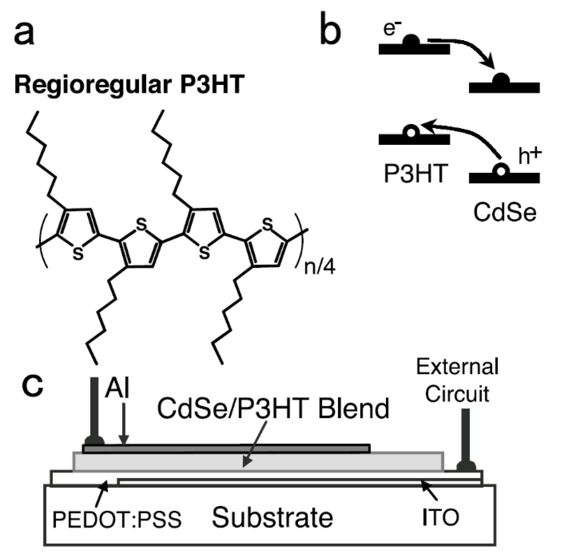
Figure 1. (a) The molecular structure of regioregular P3HT. (b) The energy level diagram of CdSe nanorods and P3HT with a schematic drawing of electron transfer to CdSe and hole transfer to P3HT. (c) The device structure consists of a 200 nm film sandwiched between an aluminum electrode and a transparent hole transfer layer (HTL) of PEDOT:PSS (Bayer AG, Pittsburgh, PA), which was deposited on the indium tin oxide electrode. The active area of the device is 3 mm2. This film was spin-cast from a pyridine chloroform solution of 90 wt% CdSe nanorods in P3HT. Reproduced with permission from [18], Copyright © 2002, The American Association for the Advancement of Science.
Applsci 10 04285 g001
Figure 2. Photoluminescence intensity of MEH-PPV: CdSe nanocrystal (NC) blends as a function of the weight fraction of CdSe NCs under excitation at 500 nm: (a) CdSe NCs prepared by Se powder, (b) CdSe NCs prepared by trioctylphosphine/Se injection. Current density–voltage (JV) characteristics of a MEH-PPV: CdSe NC device with the weight ratio of 1:8 (c) without and (d) with annealing at 180 °C for 20 min. The dotted line was measured in the dark and the solid line under 1.5 AM solar illumination. The insets are the JV curves with current density (J) expressed in logarithmic coordinates. Reproduced with permission from [22], Copyright © 2006, IOP Publishing.
Applsci 10 04285 g002
Figure 3. (a) Synthesis route for P3HT with amino end-functionality. (b) Plots of power conversion efficiency (PCE) versus the volume ratio of CdSe with polymer 4 (solid lines) and polymer 1 (dashed lines) as the donor, respectively. Note the very high reproducibility of the lowest, highest and average performance for numerous duplicating devices. Reproduced with permission from [29], Copyright © 2004, American Chemical Society.
Applsci 10 04285 g003
Figure 4. Performance enhancement in polymer: NC hybrid solar cells (HSCs) upon EDT treatment. (a) Schematic structure of polymer: NC HSCs. (b) TEM image of CdSe nanorods (scale bar: 20 nm) and chemical structures of conjugated polymers (P3HT and PCPDTBT) and EDT. The nanorods have an aspect ratio of 7. J-V characteristics of (c) P3HT:CdSe and (d) PCPDTBT:CdSe HSCs with/without EDT treatment. (e,f) Dependence of illumination power on PCE and Jsc/P0 for P3HT:CdSe and PCPDTBT:CdSe HSCs with/without EDT treatment, respectively. Reproduced with permission from [37], Copyright © 2013, American Chemical Society.
Applsci 10 04285 g004
Figure 5. (a) HSC structure and (b) band alignment of different layers. EF represents the Fermi level. Reproduced with permission from [57], Copyright © 2016, Royal Society of Chemistry.
Applsci 10 04285 g005
Figure 6. A schematic outline of the layer-by-layer process for making CdTe NC solar cells with a crosslinkable HTL. Reproduced with permission from [75], Copyright © 2019, WILEY-VCH Verlag GmbH & Co. KGaA, Weinheim.
Applsci 10 04285 g006
Figure 7. (a) J–V curves of CdTe NC solar cells with different structures (Device A: ITO/ZnO/CdS/CdTe/Au; Device B: ITO/ZnO/CdSe/CdTe/Au; Device C: ITO/ZnO/CdS/CdSe/CdTe/Au; Device D: ITO/ZnO/CdS/CdSe/CdTe/HTL/Au; (b) corresponding EQE spectra. Reproduced with permission from [75], Copyright © 2019, WILEY-VCH Verlag GmbH & Co. KGaA, Weinheim.
Applsci 10 04285 g007
Figure 8. (a) Hybrid tandem solar cell configuration and TEM cross-sectional image of the corresponding device. The scale bar is 100 nm. (b) Energy level diagram of the hybrid tandem solar cell. Reproduced with permission from [85], Copyright © 2018, American Chemical Society.
Applsci 10 04285 g008
Table 1. HSC solar cell devices with all kinds of device configurations. Device type: (A) Hybrid bulk heterojunction solar cells with semiconductor NCs as acceptors. (B) Hybrid solar cells with more active layers. (C) Hybrid solar cells using organic materials as hole transfer layers. (D) Hybrid solar cells with tandem structures.
TypeDevice ArchitectureVoc
(V)
Jsc
(mA/cm2)
FF (%)PCE (%)Published
Year
Ref.
AITO/P3HT: CdSe NC/Al0.705.7040.01.72002[18]
ITO/PEDOT: PSS/MEH-PPV:CdSe NC/Al0.902.0347.00.852006[22]
ITO/PEDOT:PSS/P3HT:CdS/BCP/Mg:Ag1.1010.9035.04.12011[34]
ITO/ PEDOT:PSS/PCPDTBT:CdSe/PFN/Al0.6910.1757.03.992014[36]
ITO/PEDOT:PSS/P3HT:CdSe NC/Al0.737.4054.02.92013[37]
ITO/PEDOT:PSS/PCPDTBT:CdSe NC/Al0.7412.8050.04.72013[37]
ITO/PEDOT:PSS/PDTPBT:PbS/TiO2/LiF/Al0.5713.0651.03.782011[47]
ITO/PEDOT:PSS/Si-PCPDTBT:PbS/ZnO/Al0.4818.2055.04.782016[50]
BITO/TiO2/CdTe/MEH-PPV:CdTe/MoO3/Au0.6013.5651.74.202016[57]
ITO/TiO2/CdTe/P3HT:CdTe/MoO3/Au0.5416.5947.24.322015[58]
ITO/TiO2/CdTe:TiO2/CdTe/PPV:CdTe/MoO3/Au0.61518.9051.76.012018[59]
ITO/ZnO/CdTe:ZnO/CdTe/PPV:CdTe/MoO3/Au0.6219.5053.96.512019[60]
ITO/ZnO/PbS/PBDTTT-E-T:IEICO/MoO3/Ag0.6629.6067.013.12019[63]
CGlass/SnO2:F/SnO2/CdS/CdTe/PEDOT:PSS/Au0.7121.4260.09.12016[71]
ITO/TiO2/CdTe NC/spiro-OMeTAD/Au0.7118.7849.26.562016[72]
ITO/ZnO/CdSe/CdTe/Si-TPA/Au0.6623.3854.18.342018[73]
ITO/ZnO/CdS/CdSe/CdTe/P-TPA/Au0.7225.3150.59.202019[75]
DITO/ZnO/PFN-Br/PBDB-T:F-M/M-PEDOT/ZnO/PTB7-Th:O6T-4F:PC71BM/MoO3/Ag1.6414.3573.717.362018[76]
ITO/PbS/WO3/Al/P3HT:PCBM/Al0.893.9053.01.82014[80]
FTO/TiO2/PbS NC/MoOx/ZnO/PFN/Polymer
-:fullerene/MoOx/Ag
1.305.7668.15.252015[81]
ITO/ZnO/PbS/MoO3/Au/ZnO/PTB7-Th/PC71BM
/MoO3/Ag
1.2710.3663.08.272017[82]
ITO/ZnO/PTB7:PCBM/MoOx/Au/AZO/PbS/
-MoOx/Au/Ag
1.3112.5056.79.42018[85]
ITO/ZnO/PbS/EDTPbS/Au/ZnO/PTBTTh:IEICO
-4F/MoO3/Ag
1.3613.6369.012.822020[86]