1. Introduction
Free-piston engine (FPE) is a new type of electrical power generation system which is a combination of the traditional technology of internal combustion engines and the up-to-date technology of permanent-magnet linear generators. It is considered to have the advantages of simple structure, high efficiency, and good renewable fuel adaptability [
1,
2,
3]. It can be used in multiple areas, such as electric vehicles, distributed power generation, and communication base stations.
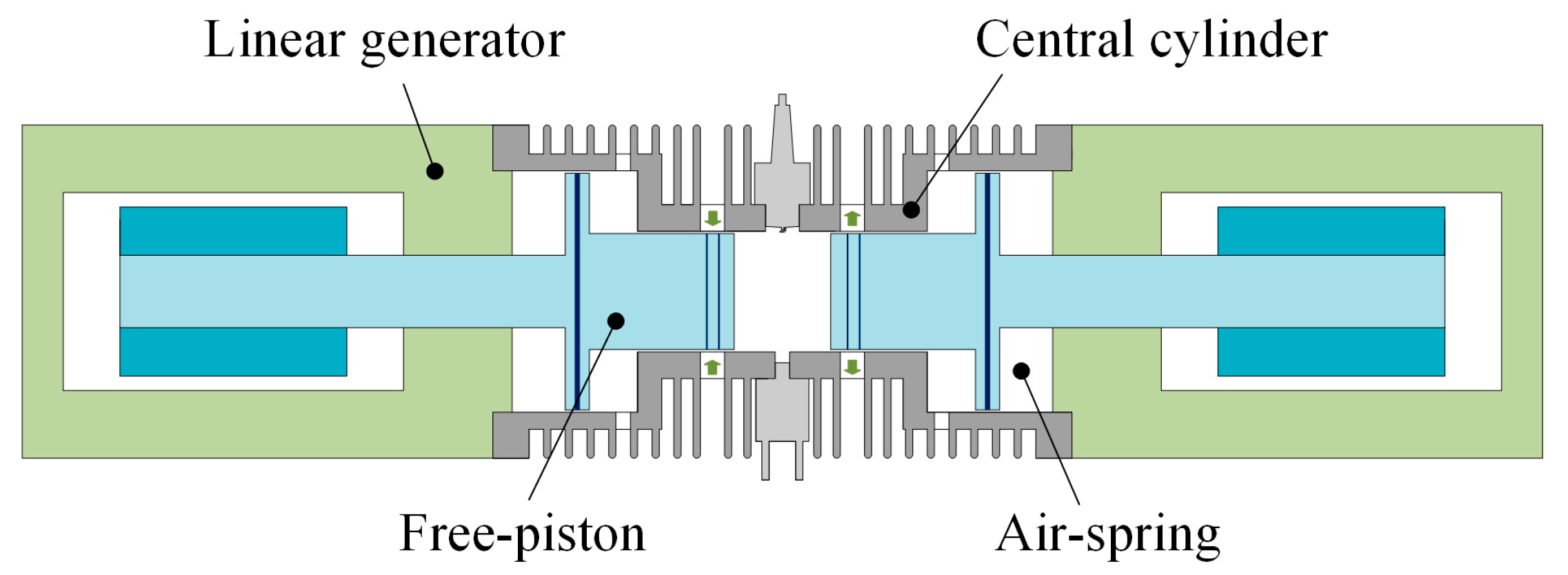
Figure 1 shows a typical composition of an opposed-piston FPE system. The system includes a central cylinder, two kickback air-springs, and two permanent-magnet linear generators. Compared with the traditional internal combustion engines with crankshafts, the pistons of FPE are without mechanical restraint, and they are connected to the mover of a linear generator. The simple structure makes the system more compact, lightweight, efficient, and reliable.
The Sandia National Laboratory [
4] has designed an opposed-piston FPE prototype. The prototype was tested to indicate that the synchronous movement of the two opposed pistons can be achieved by the control of the generating current. According to their testing results, the efficiency of the prototype can be comparable that of to fuel cells. A conversion efficiency of 50% from fuel to electricity can be obtained by the prototype when a relatively high compression ratio is used.
The German Aerospace Center [
5,
6] is currently studying the design of opposed-piston FPEs. The overall structure of the designed prototype is more compact than the prototype of Sandia National Laboratory. The performance of the prototype was tested using a test bench which used hydraulic pumps as the linear load. The researchers are trying to test the performance of a new designed prototype which uses two plate-moving magnet linear generators as the linear load.
As the key component of FPEs, the performance of linear generators plays a very important role in the electric output and electric conversion efficiency of the system [
7,
8]. The linear generator used in FPEs needs to have some strict and special characteristics, such as a good controllability, convenient manufacturing, low mover mass, and high generating efficiency [
9]. These requirements make the design of linear generators for FPEs a great challenge [
10,
11].
Wang [
12] designed a tubular three-phase moving magnet linear generator for FPEs. The electromagnetic characteristics of the linear generator were predicted by analytical expressions and finite element methods, but no prototype testing results were reported in the paper. This kind of three-phase moving magnet linear generator has the advantages of a higher efficiency and higher power density, but the generating process is difficult to control precisely.
Chen [
13,
14] designed a tubular single-phase axial-magnetized moving magnet linear generator. The electromagnetic characteristics of the linear generator under a reciprocating frequency of 75 Hz were analyzed and tested. A generating efficiency of 82% was reported. This kind of single-phase moving magnet linear generator has advantages of being compact, lightweight, efficient, and reliable, but the generating efficiency should be improved to meet the requirement of FPEs.
Xu [
15,
16,
17] designed a series of tubular single-phase moving coil linear generators for FPEs. This kind of single-phase moving coil linear generator has the advantage of having less moving mass, a faster response, and better controllability, but has the disadvantage of a lower power density. The copper loss is the main loss of this kind of linear generators and will lead to excessive temperatures of the moving coil. At the same time, the moving coil is difficult to cool.
In addition to the above linear generator research, related linear actuator researches provided more references for this study. Mercorelli and Liu [
18,
19] designed a high-force short-stroke linear actuator for applications when a very high dynamic is required. A robust control was proposed based on an adaptive proportional integral differential (PID) to stabilize the motion tracking against external disturbances. The experimental results demonstrated the excellent behavior of the system.
To meet the requirements of FPEs, this paper presents a novel tubular single-phase moving magnet linear generator which has a stable structure, low cost, good controllability, and high generating efficiency. The static and dynamic characteristics of the linear generator will be analyzed. A prototype will be manufactured to validate the simulation model. The performance of the linear generator will be evaluated and compared with a reported moving coil design.
2. Linear Generator Design
2.1. Linear Generator Structure Design
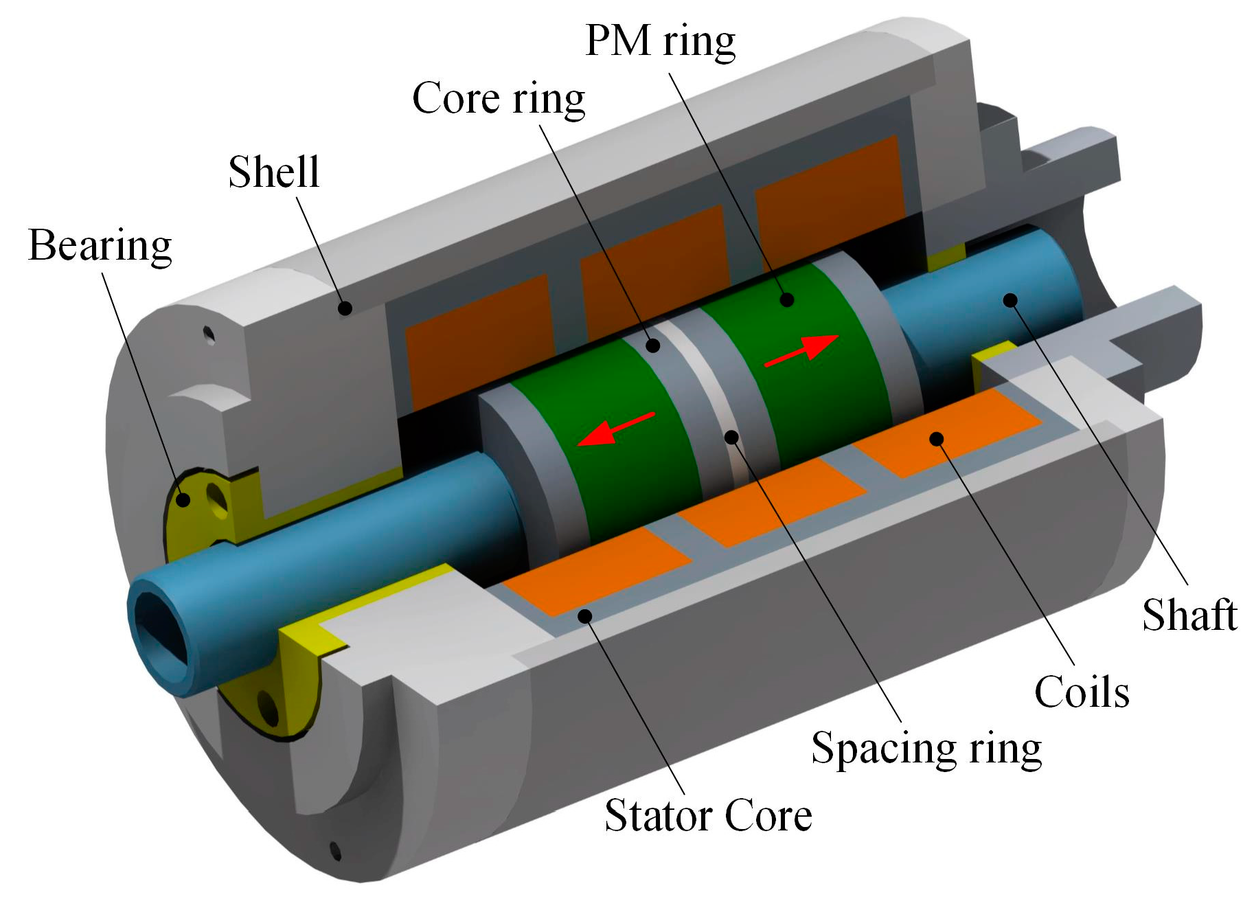
The linear generator used in FPEs must have a stable structure, low cost, good controllability, and high generating efficiency. This paper proposes a tubular single-phase moving magnet linear generator (MMLG) to meet the requirements of FPEs. A simplified three-dimensional structure of the proposed linear generator is shown in
Figure 2. As shown in the figure, the linear generator can be divided into three main parts: the stator, the mover, and the shell.
The mover of the linear generator consists of two permanent magnet (PM) rings, four core rings, and a spacing ring. The PM rings are axial magnetized with opposite directions. The core rings are laminated by a silicon steel sheet to reduce the core loss. The non-magnetic spacing ring is used to space the core rings. The structure is designed to be stable and reliable to ensure safety so that the linear generator can work at a high-speed reciprocating motion of up to 50 Hz.
The stator of the linear generator consists of the stator cores and the coils. The stator cores are laminated by a silicon steel sheet and divided into 12 identical parts for reducing the manufacturing difficulty. The coils are connected in series to form a single-phase winding. The shell of the linear generator has 12 toothed grooves, so the stator cores are fixed in the grooves. Two graphited linear bearings are installed to support and guide the reciprocating motion of the mover.
Table 1 lists the main dimensions of the designed linear generator. Additionally, the neodymium iron boron “N42SH” is used for the PM material for higher performance. The silicon steel “47F240” is selected for the core material. The aluminum alloy “7075-T6” is selected for the shell material for its low density and low magnetic permeability. A kind of high-strength plastic “POM” is used for the spacing ring material. The stainless steel “304” is used for the shaft material.
2.2. Linear Generator Controller Design
When driven by the high-speed reciprocating motion of FPEs, the electromotive force (EMF) of the designed linear generator in the last section is quasi-sine ware. The frequency of the EMF will be equal to the frequency of the reciprocating motion. This is because the reciprocating motion stroke is short than the pole pitch of the linear generator, and the direction of the EMF will be constant during a stroke. Current commutation is not needed during a stroke. This characteristic makes the current control of the single-phase linear generator easier than that of the reported designs.
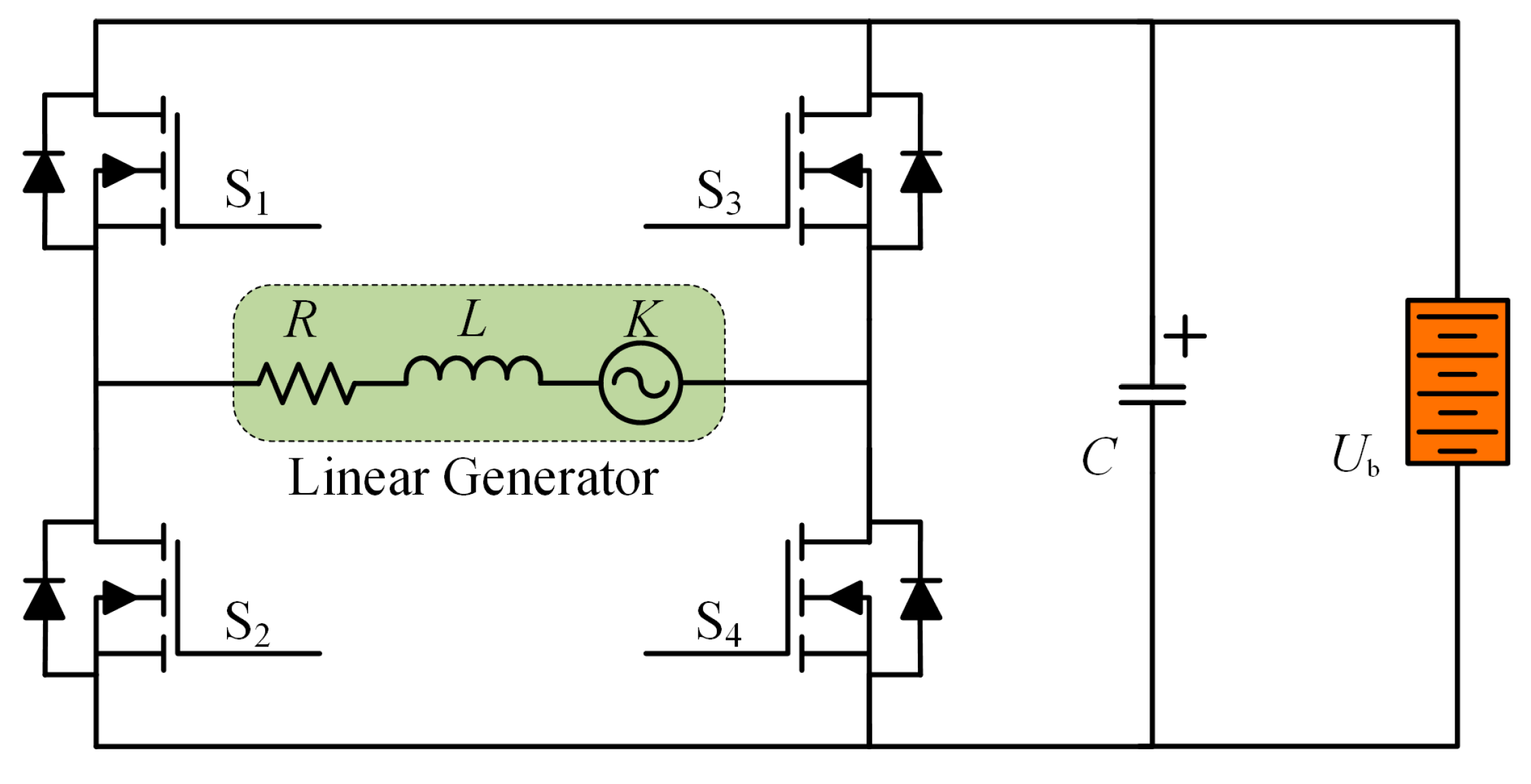
Figure 3 shows the designed power convertor for the control of the linear generator. A pulse width modulation (PWM) H-bridge power converter is designed to control the generating process of the linear generator. A standard sine ware is selected for the aimed generating current. The amplitude of the generating current is adjusted according to the needed power output. A discrete proportion integration differentiation (PID) algorithm is used for the current feedback control.
The equivalent circuit of the designed linear generator is also shown in
Figure 3. The linear generator can be equivalent to a series of the coil resistance, the coil inductance, and the EMF voltage source. The EMF can further equal the product of the EMF coefficient and the mover moving speed of the linear generator. The three electromagnetic parameters will be calculated by the finite element model, which will be created and validated in the next section.
Table 2 lists the main parameters for the control of the designed linear generator, including the control parameters and characteristic parameters of the selected power switch devices. As shown in the table, a kind of insulated gate bipolar translator (IGBT) is selected for the power switch to enable a large generating current of up to 120 A. The restricted unipolar method is used for the pulse width modulation (PWM) control. The control method can reduce the electromagnetic loss of the controller as much as possible. The parameters will be used by the model during the simulation.
The parameters for the control of the linear generator are selected according to the electromagnetic characteristics of the designed linear generator. The voltage of the battery is selected to be higher than the maximum terminal voltage of the linear generator when it is working at the rated conditions. This is because the H-bridge power convertor works in boost mode when it uses as a rectifier. The PWM frequency is selected according to the coil inductance of the linear generator. The servo frequency is selected according to the requirement of the control accuracy. The power switch devices are selected according to the latest technology of the automotive IGBT chips.
3. Electromagnetic Analysis
3.1. Finite Element Model
To analyze the characteristics and evaluate the performance of the linear generator designed in the last section, a three-dimensional finite element model (FEM) is created and a transient computing method with a motion solver is used. Compared to the simplified two-dimensional finite element model, the three-dimensional finite element model is more accurate; the end effect of the coil and the magnetic flux leakage in the stator core are considered and the eddy losses in the PM ring, the shell, and the shaft are also considered by the model. Commercial electromagnetic field analysis software was used to carry out the finite element analysis (FEA) of the model.
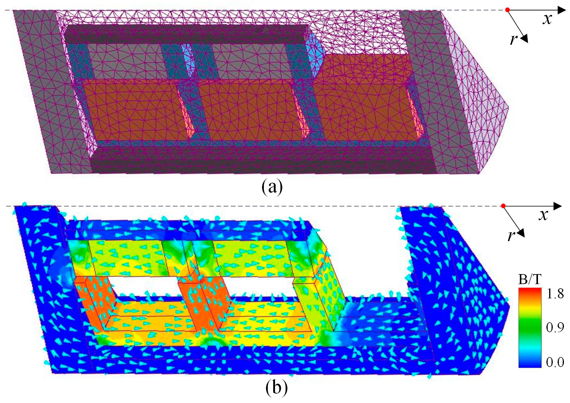
As shown in
Figure 4, the finite element model is 1/12 of the designed linear generator for reducing the computation time. The two cut surfaces of the FEM model are set as the flux tangential boundary. The model is meshed by triangular finite elements. To display the internal structure, the magnetic field in the coil and the air box of the calculation region are hidden. The mover moves along the x axis, as shown in the figure. The mover is in the start of the stroke, and it is defined as the original point. The magnetic field is mainly distributed in ferromagnetic materials. The leakage flux in the shell and the shaft is relatively small but also induces a certain amount of eddy current loss.
3.2. Combined Simulation Model
Based on the finite element model of the linear generator created in the last section, a combined simulation model is created in the software of MATLAB. A physical model of the power convertor designed in the last section is established by using the power electronics toolbox in the MATLAB software. Supported by the commercial finite element software, the finite element model of the linear generator is embedded into the software of MATLAB. The MATLAB software calls the finite element software in every time step to realize the combined simulation.
As shown in
Figure 5, the model consists of four main parts. The generator controller provides PWM signals to control the four power switch devices of the power convertor. The PWM signals are calculated based on the current feedback of the linear generator, and a discrete proportional integral differential (PID) algorithm is used by the controller. According to the difference equations described in the reference [
2,
3], the free-piston engine is modeled to output the motion to drive the linear generator.
Table 3 lists the main parameters used in the free-piston engine model.
3.3. Force Characteristics
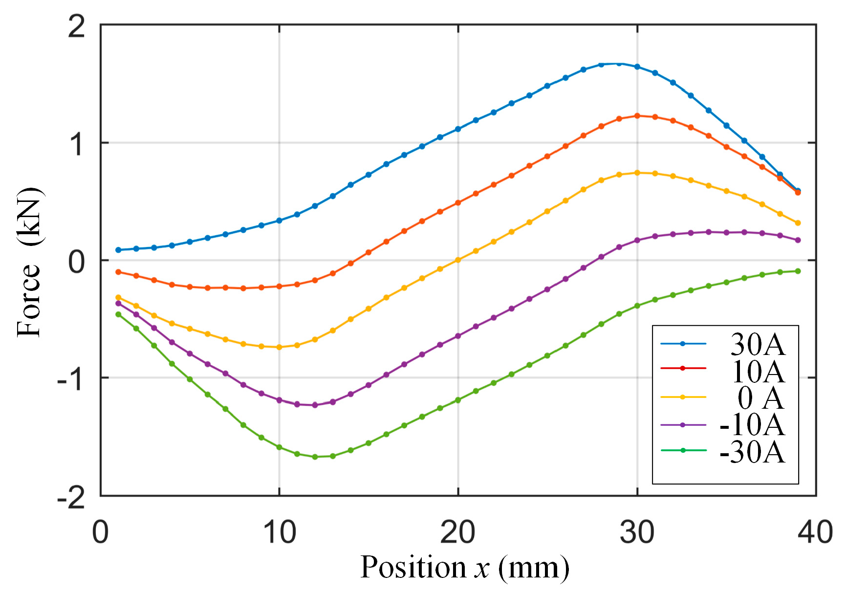
By using the three-dimensional finite element model created in the last section, the static characteristic of the designed linear generator is analyzed firstly.
Figure 6 shows the simulated electromagnetic force characteristics at the max current of 30 A and the rated current of 15 A. The max electromagnetic force is about 1670 N for the max current and 1230 N for the rated current, which is obtained at the 1/4 position of the stroke.
The max cogging force of the linear generator is about 740 N. The cogging force is designed to have only one zero position. The cogging force will let the mover stop in the middle of the stroke after the running. This is used to increase the natural vibration frequency of the reciprocating motion and to increase the power density of the system. The average electromagnetic force coefficient of the linear generator is about 12 N/A at the max current and 14 N/A at the rated current.
3.4. EMF Characteristics
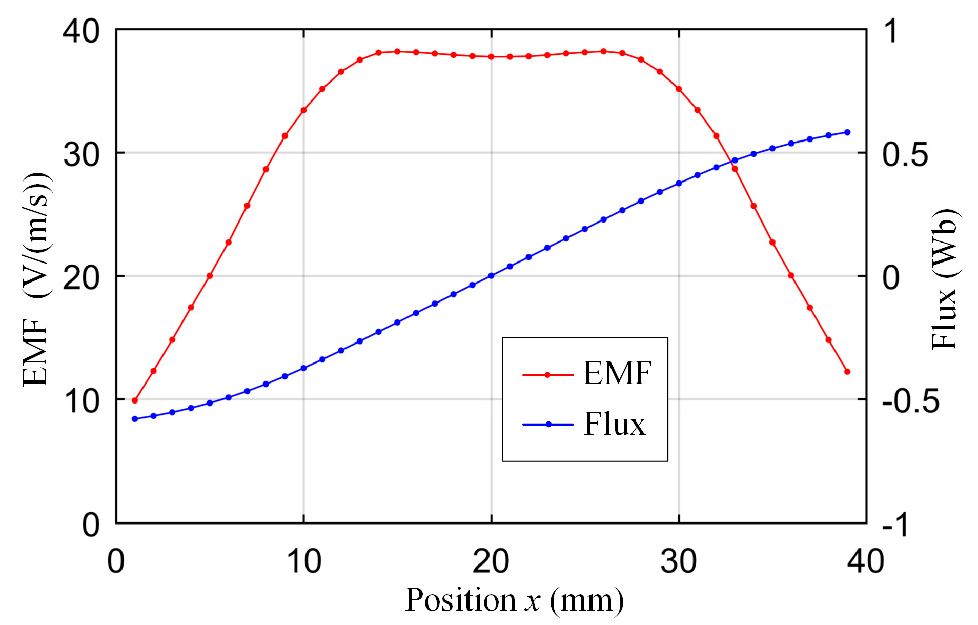
Considering that the linear generator system works in generating mode all the time during the stable running, its EMF characteristics are even more important than its force characteristics.
Figure 7 shows the EMF characteristics of the linear generator simulated at the constant reciprocating motion speed of 1 m/s. The EMF coefficient fixed at 38 V/(m/s) during the middle 1/2 area of the stroke, and the EMF coefficient decreases linearly during the both ends of the stroke.
The EMF characteristics can be explained by the flux linkage curve shown in the figure. When the current is 0 and the mover is in the midpoint of the stroke, the flux linkage in the coil of the linear generator is near to 0. The flux linkage changes linearly as the mover moves during the middle 1/2 area of the stroke, but the change rate decreases during both ends of the stroke. The EMF characteristics allows us to make full use of the motion to generate electricity.
3.5. Efficiency Characteristics
The linear generator is designed for the rated reciprocating motion frequency of 50 Hz with the rated stroke of 36 mm, which is equal to 3000 turns per minute of rotary machines. The generating current of the coil is controlled according to a standard sine ware, and the rated amplitude is 15 A. Meanwhile, due to the limitations of the test conditions, the generator will be tested in the next section at the frequency of 35 Hz with the current amplitude of 25 A.
Thus,
Figure 8 shows the efficiency characteristics of the linear generator simulated at the reciprocating motion frequency of 50 Hz and 35 Hz. The rated operation point and the tested point are also shown in the figure. The generating power of 1.4 kW with the efficiency of 91.4% can be obtained as working at the rated operation point. Meanwhile, the generating efficiency will be reduced to 84% when the working frequency is reduced to 35 Hz.
4. Prototype Research
4.1. Prototype Manufacturing
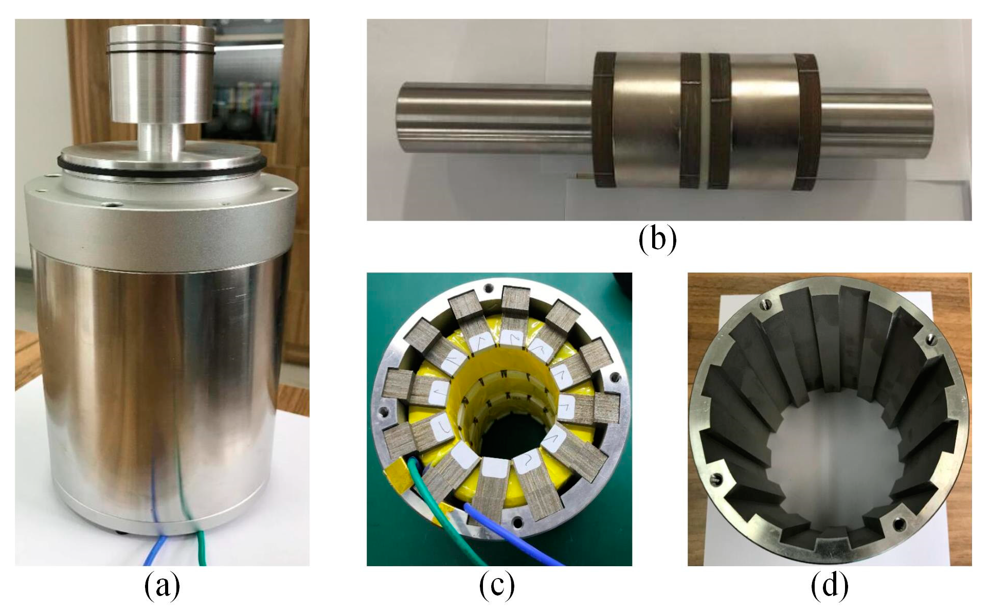
A prototype of the linear generator designed in this paper was manufactured.
Figure 9 shows the prototype and its main components. A displacement sensor is mounted inside of the shaft of the linear generator. It is a resistive position sensor with a repeatability accuracy of 0.01 mm and a max movement velocity of 10 m/s. A current sensor and a voltage sensor are mounted in the power convertor of the linear generator. The real-time mover position, coil current, and terminal voltage of the linear generator can be tested synchronously at the sampling frequency of 10 kHz.
4.2. Prototype Testing Results
To validate the performance and the characteristics of the linear generator analyzed in the last section, the manufactured prototype was tested. During the testing, the linear generator works in power generation mode and is driven by a prime motor. The linear generator converts the mechanical energy into the electrical energy. Due to the limitations of the prime motor, the prototype is tested at the frequency of 35 Hz with the generating current amplitude of 25 A.
The prototype testing results are shown from
Figure 10,
Figure 11,
Figure 12 and
Figure 13.
Figure 10 shows the tested mover motion during a stroke driven by the prime motor. The tested mover motion is compared with the mover motion simulated by the validated finite element model (FEM). The mover motion curve is designed according to the actual motion of the FPE [
17]. As shown in the figure, the time of the stroke is about 14 ms, and the max speed of the mover motion is up to 3.5 m/s. The reciprocating frequency is about 35 Hz, which is equal to 2100 turns every minute of conventional rotary engines. The reciprocating motion is not a standard sinusoidal motion. The average speed of the first half was significantly higher than that of the second half.
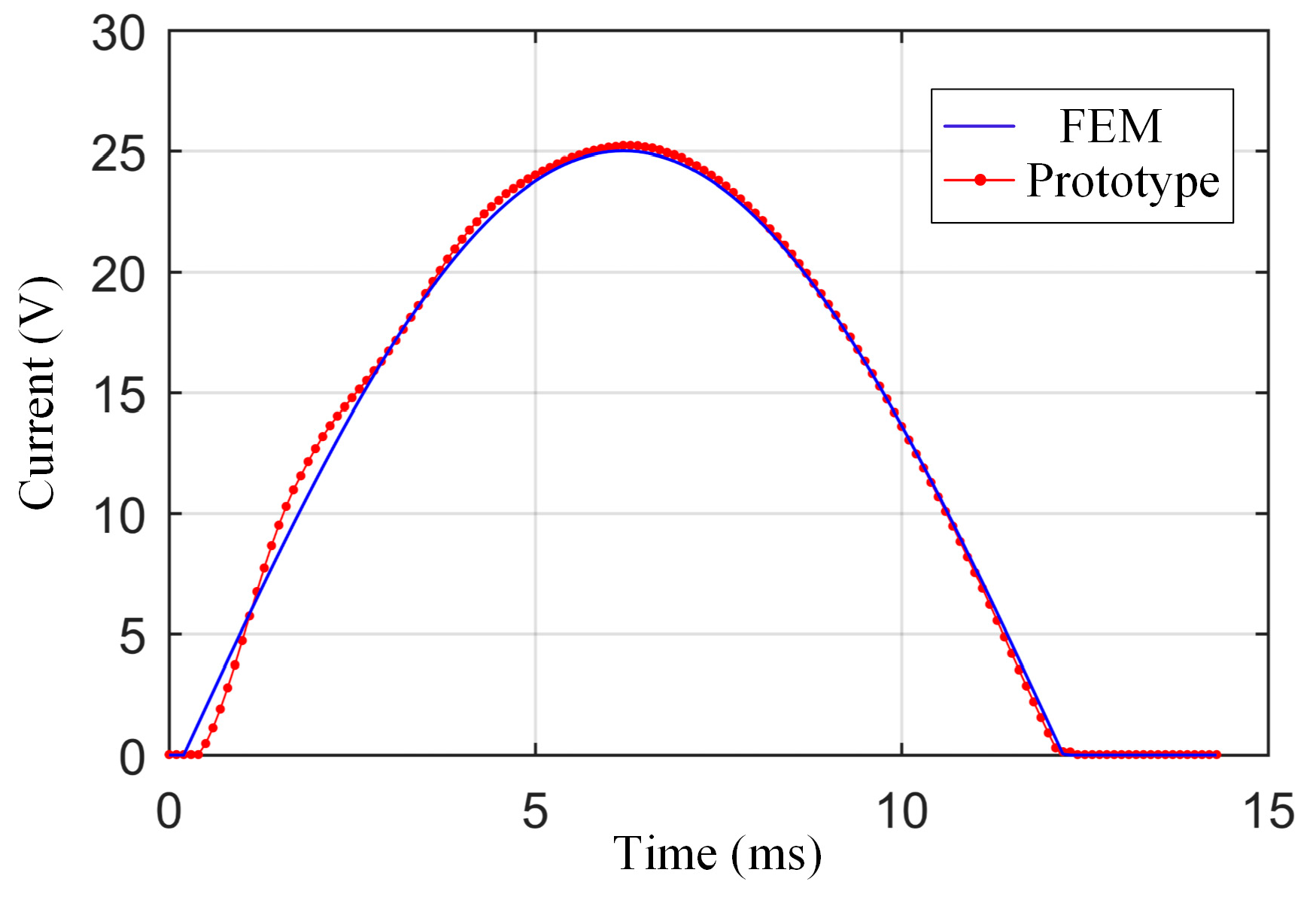
Figure 11 shows the tested and simulated currents during the stroke, and the corresponding terminal voltages are shown in
Figure 12. The generating current is a standard sine wave controlled by the controller. The amplitude of the generating current is 25 A, and the root mean square (RMS) current is 17.1 A. A short reverse voltage needs to be provided to create the generating current at the beginning of the stroke. The test curve and the simulated current curves agree well. The tested average coil current is about 0.2% higher than the simulated, and the tested average generating voltage is about 5% higher than the simulated. At the end of the stroke, the aimed generating current is set to zero, as the terminal voltages are lower than the battery voltage at this stage.
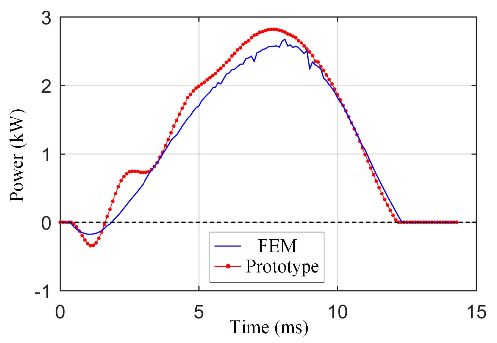
Figure 13 shows the tested and simulated generating power during the stroke. It is calculated by multiplying the instantaneous terminal voltage by the instantaneous coil current. As shown in the figure, the tested peak generating power is 2.8 kW at the midpoint of the stroke. The tested average generating power is 1.4 kW. The short negative power at the beginning of the stroke is used to create the generating current, as well as the short reverse voltage shown in the voltage curve. The tested average power is about 6% higher than the simulated. This difference is mainly caused by the manufacturing differences of the prototype. The actual performance of the permanent magnet used in the prototype is likely to be higher than that used in the simulation model.
4.3. Prototype Performance
After being validated by the prototype testing results, the simulation model is used to evaluate the performance of the linear generator prototype at the rated motion frequency of 50 Hz, the rated stroke of 36 mm, and the rated current amplitude of 15 A. The main performance parameters of the linear generator prototype are shown in the
Table 4 and are compared with the latest reported tubular moving coil linear generator prototype in reference [
17].
The generating efficiency is calculated by dividing the electrical energy output by the mechanical energy input during a stroke. The electrical energy output during a stroke is obtained by integrating the instantaneous electrical power output, which is calculated by multiplying the instantaneous current by the terminal voltage of the coil. The mechanical energy input during a stroke is obtained by integrating the instantaneous mechanical power input, which is calculated by multiplying the instantaneous electromagnetic force by the motion speed of the mover.
Compared with the reported moving coil linear generator prototype (MCLG), the new moving magnet linear generator prototype (MMLG) has a more stable structure and better power density. Meanwhile, the mover mass of the moving coil prototype is smaller than that of the moving magnet prototype. Except for the power density and the mover mass, the other parameters of the two prototypes are similar, and both can meet the requirements of the FPEs.
Table 5 shows the losses of the designed tubular moving magnet linear generator prototype when it is working at the rated motion frequency of 50 Hz, the rated stroke of 36 mm, and the rated current amplitude of 15 A. The losses in the copper, the magnet, the core, and the shell are considered. It is obvious that the loss of the linear generator mainly comes from the copper loss, which can be cooled together with the stator. The loss in the moving magnet is relatively small.
5. Conclusions
In this paper, a novel tubular moving magnet linear generator is proposed for the application of free-piston engines. Based on the three-dimensional finite element model, a combined simulation model of the system is created in the software of MATLAB. A prototype is manufactured and tested at the frequency of 35 Hz with the generating current of 25 A to validate the model. The electromagnetic characteristics and performances are simulated and analyzed in detail.
The electrical power output of 1.4 kW with the efficiency of 91.4% is obtained by the designed moving magnet linear generator when it works at the rated working frequency of 50 Hz, the rated stroke of 36 mm, and the rated current amplitude of 15 A. The loss of the linear generator mainly comes from the copper loss. Compared the moving coil, the loss in the moving magnet is greatly reduced, and thus the structure is more stable for avoiding overheating for long-term operation.
Compared with the reported moving coil linear generator with a similar efficiency, the new single-phase moving magnet linear generator designed in this paper has a more stable structure and higher power density. Compared with the reported three-phase moving magnet linear generator, it has a better controllability to enable free-piston engines working at a high-speed reciprocating motion of up to 50 Hz. It is a more suitable choice for the application of free-piston engines.


