Article

Numerical Analysis Based on a Multi-Body Simulation for a Plunging Type Constant Velocity Joint

Institute of Mechanics, Faculty of Mechanical Engineering, Otto von Guericke University, Universitätsplatz 2, 39106 Magdeburg, Germany
*
Author to whom correspondence should be addressed.
Appl. Sci. 2020, 10(11), 3715; https://doi.org/10.3390/app10113715
Submission received: 15 April 2020 / Revised: 20 May 2020 / Accepted: 22 May 2020 / Published: 27 May 2020
(This article belongs to the Section Mechanical Engineering)

Abstract

:
In early design phases of ball typed constant velocity joints (CVJ), which are widely used for the uniform transmission of rotational movement in driveshafts, the knowledge of the interactions between the components is essential. Therefore, a simulation model for a multi-body analysis is developed to consider general, transient operating conditions of the joint in the development process. The model is derived using the example of a plunging joint of the rear prop shaft, which has a straight track geometry and two track angles. On this basis, a two-dimensional, analytical contact determination between balls and tracks can be carried out, which reduces the required computation times compared to a general contact determination. Although rigid bodies are used for numerical analysis, local elastic deformations between the contact bodies are possible on the basis of Hertzian contact theory. For a higher level of detail, frictional forces are also taken into account via the Coulomb friction law, which is adapted for numerical use. To validate the simulation model, the influences of the numerical parameters are discussed and the numerical results are compared with the analytical results of the statically undeflected joint condition. Finally, the created simulation model is utilised to present the numerical joint analysis using two examples of joint kinematics analysis.

1. Introduction

In the course of the permanently increasing requirements for energy efficiency and careful use of resources, CVJs offer a great potential for optimisation through material savings and efficiency improvement, since they are used in many technical applications for the uniform transmission of rotary motion and torque. However, the current design and optimisation of these joints is largely founded on many years of experience based on analytical design methods for the statically undeflected load case of the joint. Nevertheless, to take dynamic influences on the joint behaviour into account during the development process, complex and cost-intensive test bench investigations are necessary. For this reason, numerical analysis of the CVJ using multi-body simulation is a suitable method to consider dynamic effects and to characterise the joint behaviour under different influencing parameters at an early stage of development.
To analyse the forces acting in a double offset joint (DOJ) and the resulting joint kinematics, Hayama [1] used the MBS program ADAMS in conjunction with Hertzian contact theory. The contacts are determined internally in ADAMS. However, in his analysis, he neglected the friction between the components at first. Kimata et al. [2] then considered these frictional forces for fixed and plunging typed joints, which are incorporated into the analytical description of the joint in order to finally solve it numerically via an ordinary differential equation (ODE) solver without a commercial software. They also compared the calculation results with experimental data at test bench for the secondary torque in DOJ [3]. Serveto et al. [4] also referred to these results and investigated the influence of friction on the secondary torque occurring in the joint as well. Similar to Kimata et al., they considered frictional forces in proportion to the contact normal forces with the help of Coulomb’s law. They identified possible noise, vibration and harshness (NVH) phenomena by implementing user-defined routines in ADAMS and performing their own measurements. For the analysis of the NVH-effective forces in a front sideshaft consisting of a ball CVJ and a tripod joint, Lim et al. [5] used a similar approach to Serveto et al., but implemented it in DAFUL software. The contact determination in the ball joint is analytical, but they formulate their model with kinematic constraints, so that the use of a differential algebraic equation (DAE) solver is necessary, which means a higher numerical effort by considering algebraic constraints [6]. Pennestri and Valentini [7] chose a fundamentally different approach for the numerical observation of a pilot lever joint, in which they defined sets of curves in the respective tracks, onto which the balls are forced by corresponding force laws. In this way, they presupposed the position of the balls a priori, which is why they cannot be adjusted freely on the basis of the acting forces. In this case, there is a chance of missing out on phenomena that occur in reality. In addition, Valentini [8] and Pennestri et al. [9] presented analytical approaches for taking manufacturing deviations in joint analysis into account. Shen [10] used the MBS program SIMPACK for his analysis of plunging joint with straight tracks, in which a general contact determination between balls and tracks is carried out by applying the polygonal contact model of Hippmann [11]. Although this approach allows the contact between arbitrary geometries to be checked, it is more computationally intensive due to the general determination of contact, which is disadvantageous for extensive parameter studies in the early development stage. Furthermore, with the mesh size there is an additional numerical parameter, which influences the calculation results and must therefore first be verified.
The listed works deal with different joint geometries in contrast to the plunging joint considered in this paper. It has a track geometry defined by straight tracks and is characterised by a double inclination for each track. This results in crossed track pairs, which are arranged alternately in the inner and outer race. In the cross-section, all tracks have an elliptical contour. However, the field of application for these CVJs is smaller than that of the DOJ, which are used, e.g., in the front sideshaft of vehicles, so that there is no comprehensive version for the kinematic simulation of these joints available so far. The present work is intended to close this gap and to provide a tool that complements the design process of CVJ with straight tracks and allows first numerical analyses to be performed focused on a most efficient variant, which is why an analytical contact determination is chosen. Only free bodies are considered, so that the positions of the individual joint bodies result exclusively from the forces acting in the joint. This also allows the use of an ODE solver, which means less numerical effort compared to a DAE solvers.

2. Theory

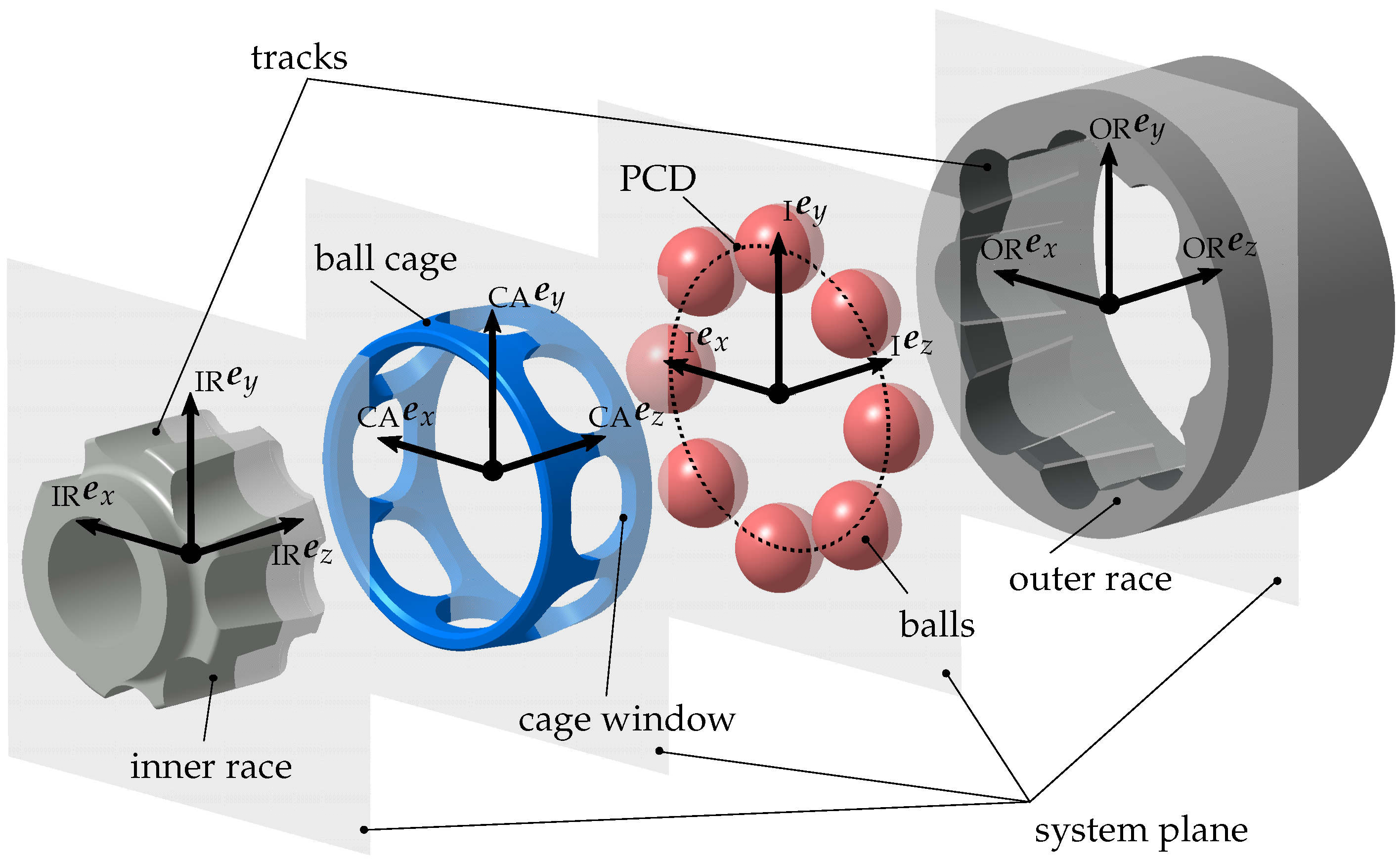
Figure 1 illustrates the basic design of a constant velocity ball joint of this type. The inner race and the outer race are each connected to a rotating shaft and have several tracks, so that a positive transmission of the torque takes place in the joint between the name-giving balls and the tracks. Further, for numerical analysis using multi-body simulation, it is necessary to define fixed coordinate systems for all joint components in addition to the inertial system   I e , which are also shown in Figure 1. For the undeflected state of the joint, all ball centres in the system plane are located on the pitch circle diameter (PCD) of the joint. As the joint rotates, the balls are positioned over the ball cage in the bisecting plane to ensure uniform rotary transmission [12]. For this purpose, it has recesses called cage windows. In addition, the joint is filled with grease to achieve a better tribological behaviour and to reduce wear. Depending on the intended use of the joint, the designs of the track geometries differ.
The analysis of the CVJ is carried out by applying the multi-body simulation under the assumption of rigid bodies. The algorithm was implemented in the MBS software EMD, which was developed at the Institute of Mechanics of the Otto von Guericke University Magdeburg. A detailed description of the functionality can be found in the dissertation of Daniel [13]. First, the differential equations of motion for spatial dynamics are established
M · a + h ω = h a ,
where M is the mass matrix, a is the acceleration vector, h a is the vector of external forces and moments and h ω is the vector of centrifugal, gyroscopic and Coriolis forces. A derivation of the individual components can be found in [14,15]. Considering only free bodies, the analysis is performed using an ODE solver for the numerical solution of the differential equation. For this reason, the ODE of second order must be transformed into a differential equation system of first order. For this purpose, the state space vector and its time derivative
  I z =   I r A p   I r ˙ A   I ω T ,
  I z ˙ =   I r ˙ A p ˙   I r ¨ A   I ω ˙ T ,
are defined, which contain the positions   I r A , the translational velocities   I r ˙ A and the accelerations   I r ¨ A relative to the inertial system   I e as well as the orientation parameters p and the angular velocities   I ω and their time derivatives. The translational parameters are specified in Cartesian coordinates
r A = x y z T ,
while different forms are implemented for the orientation parameters p . Cardan angles are used to analyse the results, while quaternions are used to solve the system of equations in order to avoid the gimbal lock [16]
p = α β γ T and p = p 0 p 1 p 2 p 3 T .
After the transformation into the state space and the conversion according to the unknown time derivative, the equation
z ˙ = M 1 h a ( z ) h ω ( z ) ,
results, which can be committed to the solver.
Since the present system has a very stiff numerical behaviour, a stable solution can only be guaranteed by implicit methods [17,18]. For this purpose, the implicit trapezoidal method [18] with an adaptive step size control is used
z i + 1 ( j + 1 ) = z i + s 2 z ˙ i + z ˙ i + 1 ( j ) , j = 0 , 1 , 2 , .
Here, s is the step size, i is the index for the current time step and j is the respective iteration step within the time step.
The multi-body simulation starts with the current positions and velocities of the corresponding bodies. These are determined by solving the differential equations from the previous time step. For the initial state, a definition of initial conditions is made. Starting from the current positions and velocities, a contact determination between the bodies is performed to determine a possible penetration, which is used to calculate the contact forces acting on the bodies. The coupling of the bodies in the multi-body simulation is done by the vector of external forces h a . After the contact forces for each body have been determined and entered into the vector of the right hand side, the solution of the differential equation can be done by the procedure described above and the state vector can be calculated for the following time step.

3. Simulation Model

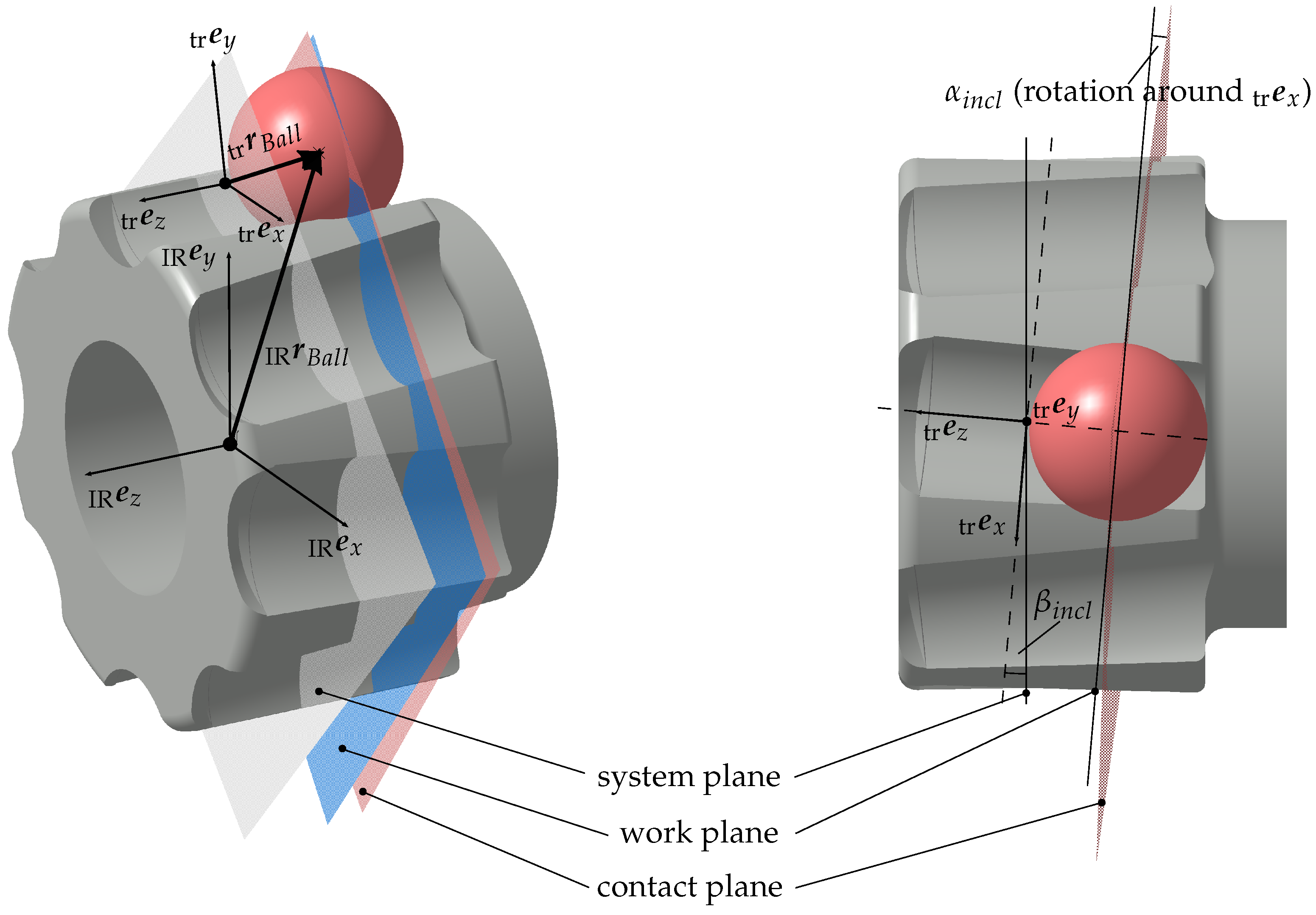
To analyse the joint kinematics using multi-body simulation, it is first necessary to define suitable coordinate systems. Therefore, a Cartesian inertial system is introduced, whose global z-axis corresponds to the rotational axis of the outer race. In addition, body-fixed coordinate systems are defined on the inner race   I R e , the outer race   O R e and the cage   C A e , whose origins lie in the joint system plane (see Figure 1). Starting from the body-fixed coordinate systems, several coordinate systems are introduced for each track and for each cage window. While the alignment of the coordinate systems in the cage window corresponds to the cage fixed coordinate system, the track coordinate systems   t r e follow the track orientation with the two track angles α i n c l and β i n c l . The transformation into the track coordinate system is performed sequentially using the matrix
Q t r I = 1 0 0 0 cos ( α i n c l ) sin ( α i n c l ) 0 sin ( α i n c l ) cos ( α i n c l ) · cos ( β i n c l ) 0 sin ( β i n c l ) 0 1 0 sin ( β i n c l ) 0 cos ( β i n c l ) .
In Figure 2, the position of the described track coordinate systems is illustrated using the inner race as an example.
Based on the defined coordinate systems, various coordinate transformations can be carried out to enable analytical contact determination for the entire joint. This applies to the ball track as well as to the ball cage contact, which is explained in detail in the following.
Up to six potential contact points are possible per ball, two per track and two more in the cage window. In the entire joint, therefore, a large number of potential contact points must be evaluated for each time step of the numerical integration, which can lead to high computing times under arbitrary circumstances. The considered track geometry allows implementing an analytical contact determination, which is based on the observation of simple geometric shapes. Thus, a complex three-dimensional contact analysis can be obviated, ensuring a fast and stable contact routine. This also guarantees that an efficient contact routine is maintained for different variations of the track parameters, e.g., the ball size or the PCD. This is necessary because a low computing time with sufficient accuracy is of utmost importance for parameter studies and design optimisation in an early step of the product development process.
The analytical contact determination is derived from the joint system plane for both ball track contact and ball cage contact for the undeflected state of the joint. Based on the considered track angles of each track, the balls move out of the joint system plane as a result of the deflection or axial displacement of the inner race. Hence, both the PCD and the distance between the ball centres along the PCD change. This leads to additional transformation steps.
For ball track contact, the current ball position is evaluated with respect to the track coordinate system   t r e , so that a corresponding contact plane   P e (red, Figure 2) can be defined orthogonal to the track axis as a function of the ball position. After the transformation of all necessary coordinates into the contact plane, the two-dimensional contact determination is performed by calculating the distance between the centres of two circles in order to identify the maximum plane penetration d between   P C 1 and   P C 2 of the contact bodies along the normal vector   P e 1 (see Figure 3a). Subsequently, the identified contact points   P C 1 on the track and   P C 2 on the ball surface are transformed into the inertial system and the maximum spatial penetration δ is determined for further force calculation
  p C 1 =   p M t r +   p e 1 · R t r ,
  p C 2 =   p M b a l l +   p e 1 · R b a l l ,
  p e 1 =   p M b a l l   p M t r | |   p M b a l l   p M t r | | ,
d =   I C 2   I C 1 ,
δ = | | d | | .
Here,   P M t r is the centre of the track flank,   P M b a l l is the centre of the ball, R t r is the track radius, R b a l l is the ball radius, d is the vectorial penetration between the contact bodies and | | d | | is the Euclidean norm of it.
An analytical approach is also chosen for the cage ball contact, but this is implemented three-dimensionally (see Figure 3b). First, a contact plane is defined on the respective window edge by a normal vector   C A n P and a receiving point   C A r c w in the body fixed cage coordinate system   C A e . Then, a potential contact point on the sphere surface
  C A C 2 =   C A r b a l l +   C A n P · R b a l l
is defined from the normal vector of the plane   C A n P , the centre of the sphere   C A r b a l l and the radius of the sphere R b a l l . After a transformation of the potential contact point on the ball   C A C 2 and the normal vector of the contact plane   C A n P into the inertial system   I e (resulting in   I C 2 and   I n P ), the distance between plane and potential contact point can be determined
δ =   I n P , x ·   I C 2 , x +   I n P , y ·   I C 2 , y +   I n P , z ·   I C 2 , z | |   I n P | | .
Finally, if the contact is positive for δ > 0 , the contact point in the cage window can be calculated as the point for the force application
  I C 1 =   I C 2   I n P · δ .
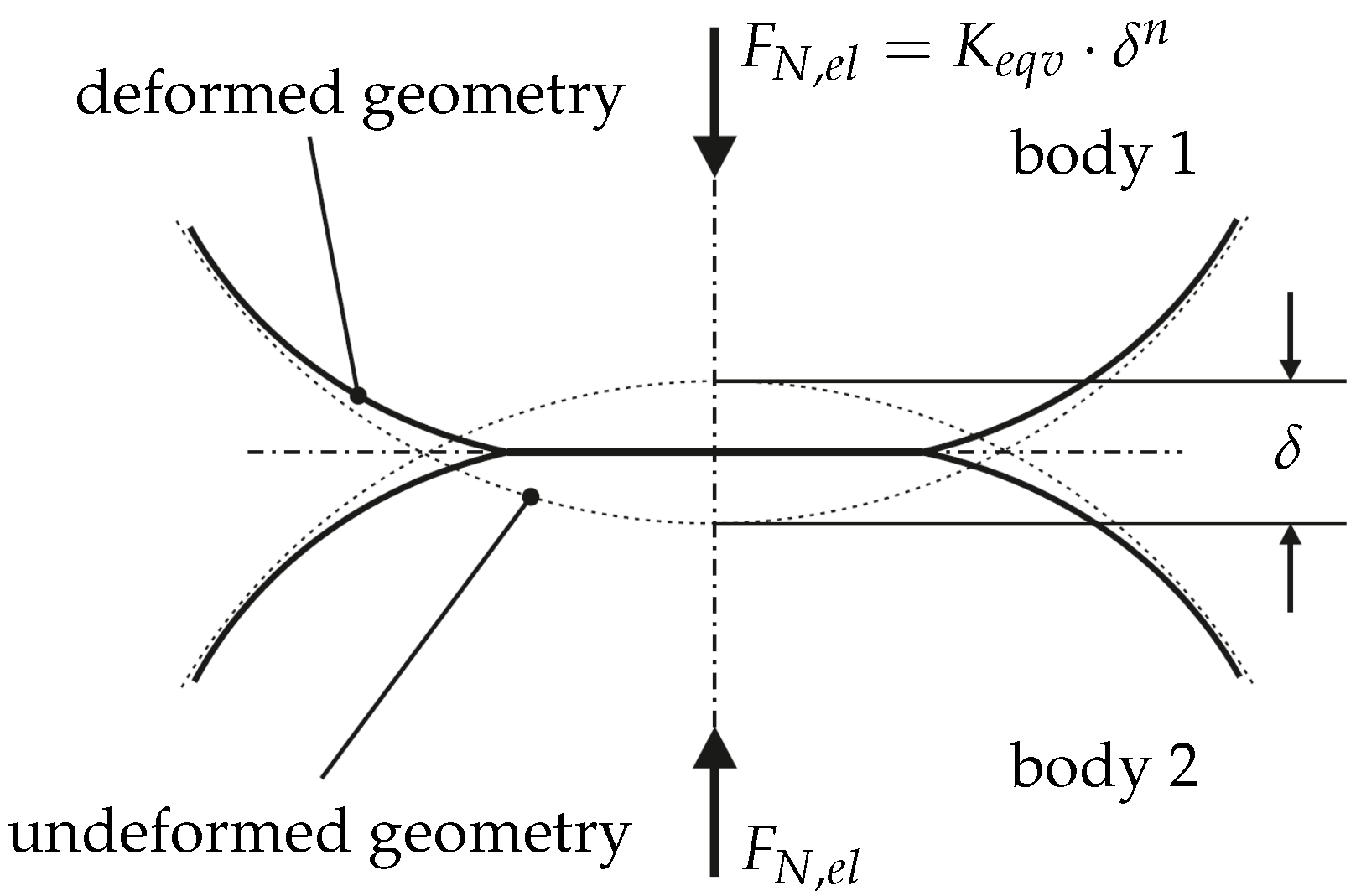
In the present work, a one-dimensional approach is used to calculate the contact forces with high efficiency, since this approach provides sufficient accuracy while maintaining a low level of complexity. In this case, the contact force acts exclusively along a direction vector between two contact points. The elastic component of the contact normal force is therefore calculated with the previously determined penetration based on the Hertzian contact theory [19], so that the penetration between the bodies can be interpreted as a local elastic deformation (see Figure 4). Mathematically, this can be described as a power law according to Johnson [20]. Besides an elastic force component, a simple viscous model for numeric stability is also used, so that the following equation according to Hunt and Crossley [21] results for calculating the contact normal force F N
F N = ( K e q v · δ n + D · δ ˙ ) · n 1 ,
with the equivalent contact stiffness K e q v calculated according to the method of Hamrock and Brewe [22] for the Hertzian contact theory, the scalar penetration δ , the exponent n, the scalar penetration velocity δ ˙ , the damping constant D and the contact normal vector n 1 for the respective contact between ball and track or ball and cage. However, the choice of the damping parameter D is not exclusively physically motivated. In real systems, damping occurs during the contact process, but this force component can be neglected compared to the elastic force components in the present application, because the elastic force components are significantly larger, which is why the viscous force components have only a minor influence on the kinematics. Rather, the damping component is used for numerical stabilisation during time integration, since in this way oscillations in the contact process are reduced. While the choice of damping constants initially has a negligible influence on the system kinematics within a certain range, it should be noted that, due to the selected force approach, the use of a damping constant that is too high can lead to tensile forces between the contact bodies when they come out of contact, which may result in unphysical system behaviour.
Frictional forces F T in the joint are implemented via Coulomb’s friction law [23] in proportion to the normal contact force F N . These forces act in the direction of the resulting tangential velocity v t between the two contact bodies,
F T = μ ( v t ) · F N · v t | | v t | | ,
v t = v r e l v n ,
v r e l = v 2 + ω 2 × r C , 2 v 1 + ω 1 × r C , 1 ,
v n = δ ˙ · n .
Here, v r e l is the relative velocity between the contact bodies, v n is the velocity in contact normal direction, v i is the translational velocity of each contact body, ω i is the rotional velocity of each contact body and r C , i is the vector from centre of gravity to the contact point for each contact body.
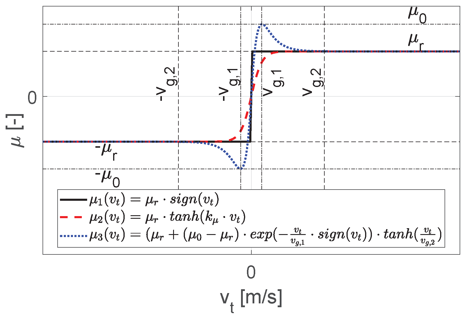
The behaviour of the friction coefficient μ ( v t ) is not represented by a simple signum function (see Figure 5, μ 1 ( v t ) ), but is approximated for numerical conversion by a continuously differentiable function, so that a discontinuity at v t = 0 is avoided (see Figure 5, μ 2 ( v t ) ). Normally, adhesive forces between the contact bodies are taken into account in the multi-body simulation via switching functions. However, this requires a high numerical effort. To be able to approximate adhesive forces at low relative velocities avoiding switching functions, the following approach according to Daniel [13] is used
μ 3 ( v t ) = μ r + ( μ 0 μ r ) · exp v t v g , 1 · sign ( v t ) · tanh v t v g , 2 .
Here, μ r is the coefficient of sliding friction, μ 0 is the coefficient of static friction, v g , 1 is the first critical velocity and v g , 2 is the second critical velocity.

4. Verification

4.1. Contact Stiffness

To guarantee the functionality of the simulation model, it is necessary to verify it first. Therefore, the influence of the numerical contact parameters on the joint kinematics is investigated. These parameters must be chosen in such a way that the model behaviour corresponds as closely as possible to the real joint behaviour. This includes, above all, that the homokinetic condition [12] be fulfilled, which is characterised by the position of the balls in the bisecting plane between the inner and outer race (see Figure 6). However, due to the chosen approach, which allows penetrations between the contact bodies, this cannot be completely fulfilled. For this reason, a compromise must be found for the contact stiffness, under which a sufficient fulfillment is guaranteed.
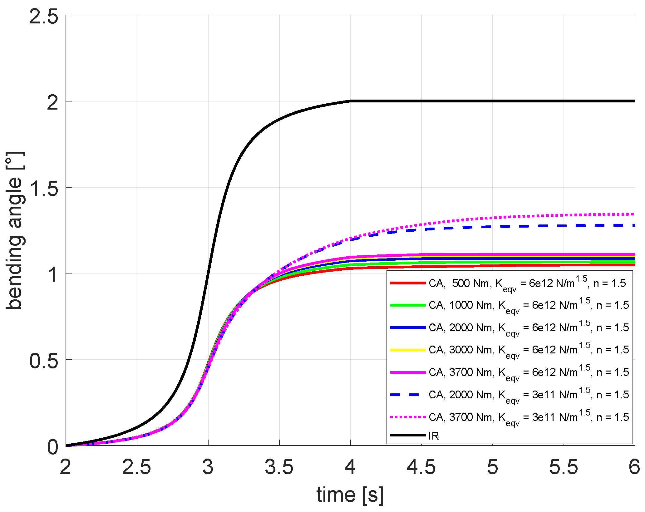
In a previous work [25], it is shown that the use of the contact stiffnesses listed in the literature, which were calculated according to the method of Hamrock and Brewe [22] for the Hertzian contact theory, results in a too soft system behaviour for our application case. This means that the deviation from the homokinetic condition becomes too large, so that the physical behaviour of the CVJ is no longer represented sufficiently, which also leads to a high number of iterations during the numerical integration and can ultimately cause the termination of the simulation. Therefore, the equivalent stiffness K e q v was increased in such a way that the homokinetic condition is sufficiently fulfilled over the entire load range, which is shown exemplarily for the cage deflection angle in Figure 7. The cage is used for positioning the balls and must therefore also be located in the plane bisecting the angle between the inner and outer race. The diagram shows the applied deflection angle for the inner race ( β b a , I R , black) and the resulting cage deflection angles for different load moments and equivalent contact stiffnesses ( β b a , C A , coloured) over time. According to theory [12], the cage flexion angle should be set exactly at β b a , C A = β b a , I R 2 . Figure 7 shows that this is sufficiently fulfilled for contact stiffness of K e q v = 6 e 12 N m 1.5 , while there is an unacceptable deviation for contact stiffness of K e q v = 3 e 11 N m 1.5 . However, an exact fulfillment only applies to ideally rigid contact bodies, so that a deviation with increasing external load and thus elastic deformation is plausible. The divergence from the original Hertzian contact stiffness can be explained by the assumptions of Hertzian contact theory. On the one hand, this was initially derived for friction-free contact zones, which cannot be assumed in the application under consideration. On the other hand, it can be presumed that the contact area between the ball and the track is no longer sufficiently small compared to the ball surface. Finally, an ideal point contact was also assumed for the model in order to achieve the fastest possible computing times. However, based on the real wear behaviour of such joints, it can be expected that there will be flat contact between the ball and the track, which will lead to a further deviation from the assumptions made.
In addition to the homokinetic condition, the model is verified with regard to the contact forces occurring in the tracks and cage windows. For this purpose, a comparison with analytical calculation results for the statically undeflected joint condition is made. The force curves determined are shown in Figure 8. In a first approximation, the small inclination angles of the tracks can be neglected so that the analytical contact forces can be calculated using Equation (23) for the track contact forces
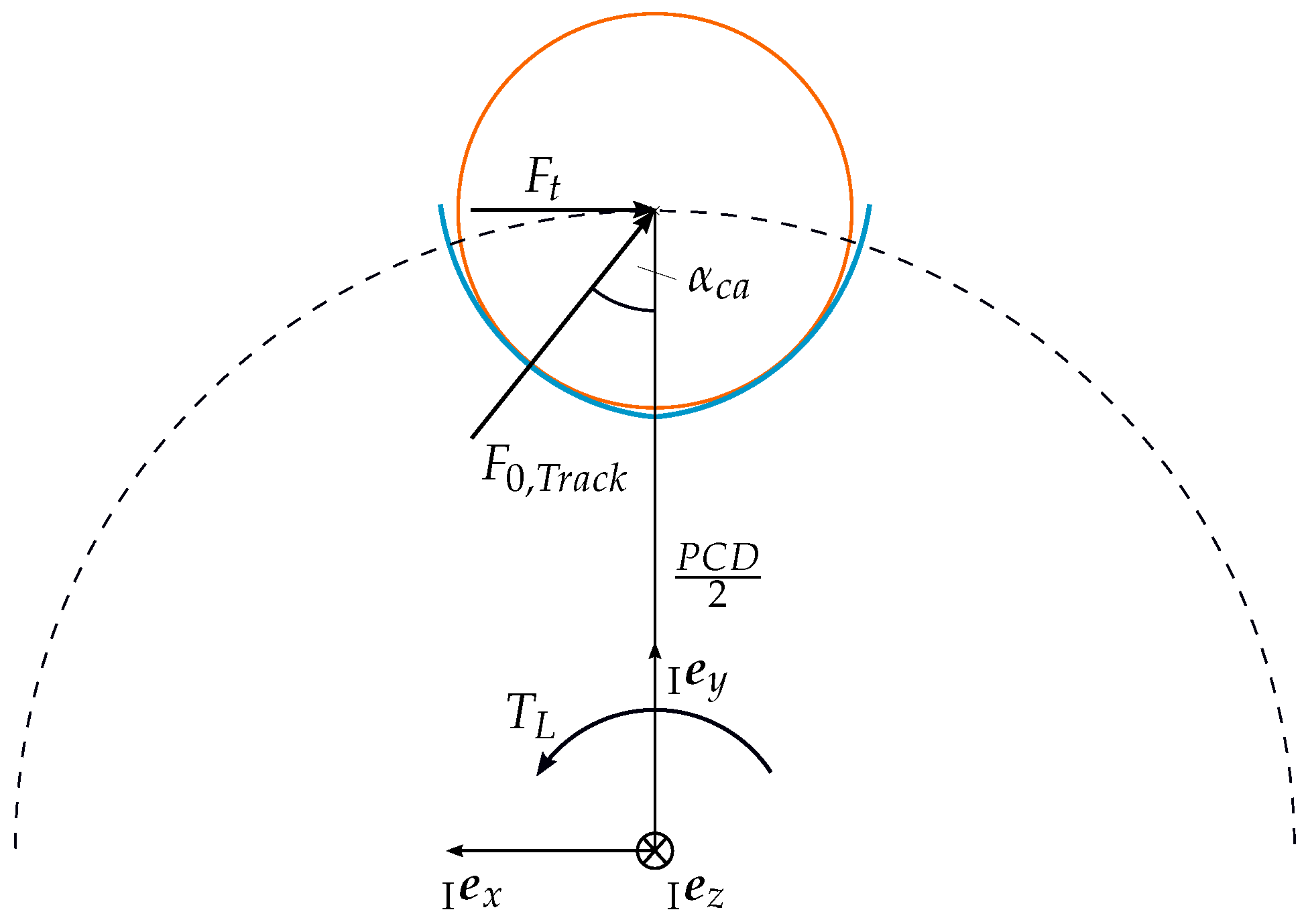
F 0 = 2 · T L m · P C D · sin ( α c a ) ,
with the load torque T L , the number of balls m, the P C D and the nominal contact angle α c a . The derivation of Equation (23) is illustrated in Figure 9. For the cage contact forces, Equation (24) can be used
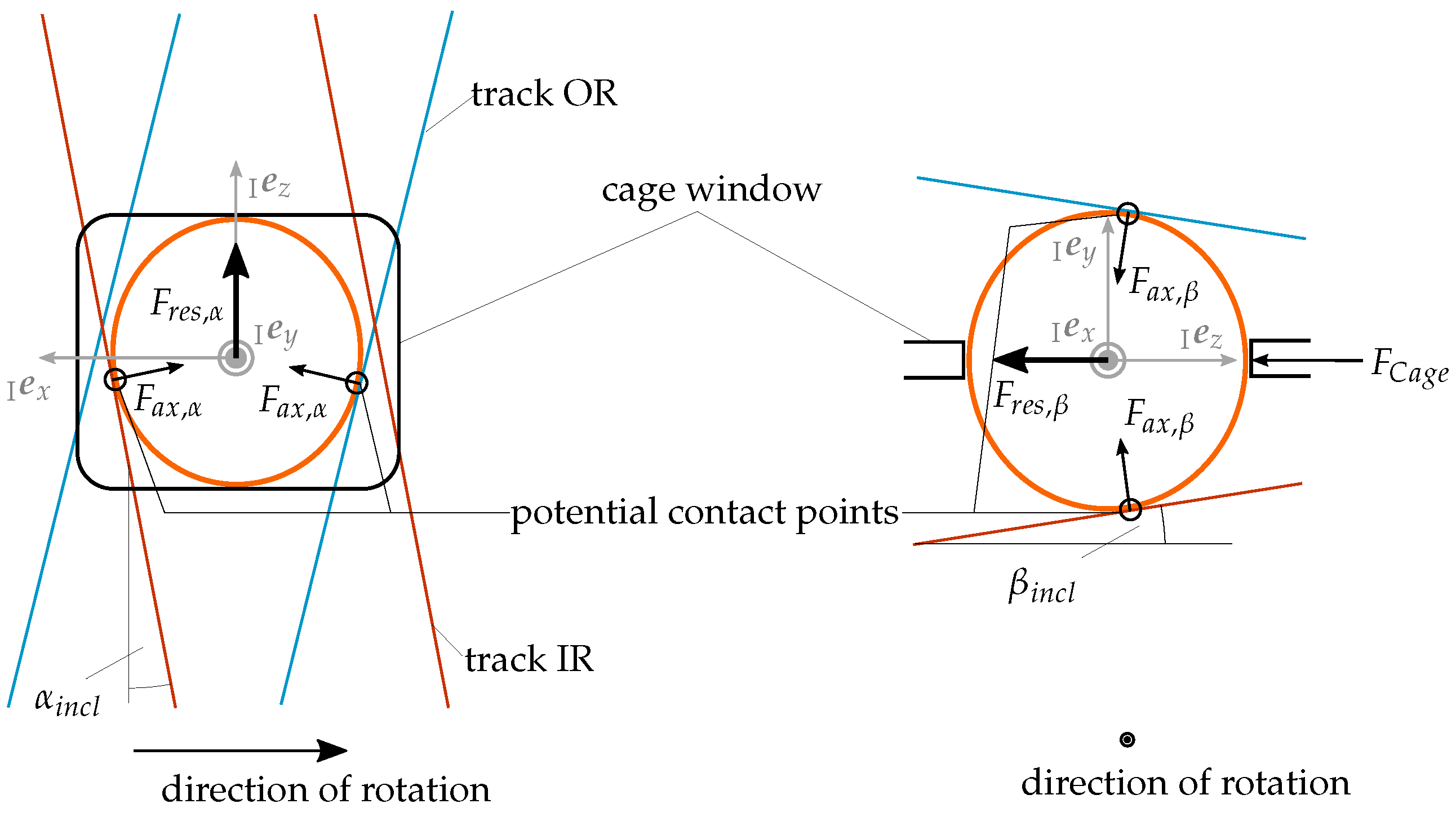
F C a g e = 2 · F 0 · ( cos ( 90 α c a ) · tan ( α i n c l ) cos ( α c a ) · tan ( β i n c l ) ) ,
where α i n c l and β i n c l are the inclination angles around the tr e x - and tr e y -axis (see Figure 10).
For the track contact force, there is a good agreement between the analytical and numerical calculation results over the entire load range (see Figure 8a). In contrast, the cage contact force shows a clear deviation in the lower load range (see Figure 8b. This is due to the fact that the axial force component F r e s , α for low load torques is absorbed by the inclination portion of the track F r e s , β , so that a certain limit torque must first be overcome before the ball contacts the cage window with the force F C a g e (see Figure 10). This limit torque is mainly characterised by the contact stiffness used, which was selected to be very high for the model to fulfil the homokinetic condition.

4.2. Friction Coefficient

Due to the approach used, the friction forces are directly proportional to the normal force, thus even small variations in the friction coefficient have a significant influence. The effect is particularly clear in connection with the secondary torque T 2 X Y in the joint, which is defined according to the authors of [4,26] as
T 2 X Y = T L · tan β b a 2 , for μ = 0 ,
with the load torque T L and the deflection angle β b a (see Figure 6). This results on the one hand from the joint geometry as soon as the joint is loaded with a torque M t in the deflected state. On the other hand, previous studies [2,4] have already shown that friction in the tracks affects the magnitude of the resulting secondary torque, which can be explained by the friction forces acting tangentially. With the model presented here, this relationship can be proven. The functional correlation between friction coefficient and secondary torque for 2000 Nm under 2 deflection angle is shown in Figure 11. For the friction-free consideration, the secondary torque can be verified from Equation (25), while an approximate quadratic dependence for the consideration of friction between the coefficient of sliding friction μ r and secondary torque is obtained for the case of T L = 2000 Nm and a deflection angle of 2 . The quadratic regression function for low friction coefficients ( μ r = 0.00–0.05, red line) is given in the legend of Figure 11. Considering the other data points with higher friction coefficients, a clear deviation from this regression function is shown. Moreover, the negative coefficient of the linear part of the regression function for all data points (blue line) cannot be physically motivated. A possible explanation for this behaviour is the superposition of the high contact stiffness with the simple Coulomb’s law, which leads to very high friction forces and thus to a significant increase in the secondary moment. At this point, the need for a more detailed friction model becomes obvious. One possible approach would be to calculate the frictional forces using the Padé approximation [27]. In this case, it is possible to consider the real track geometry and still obtain the computationally efficient performance of the analytical contact determination.
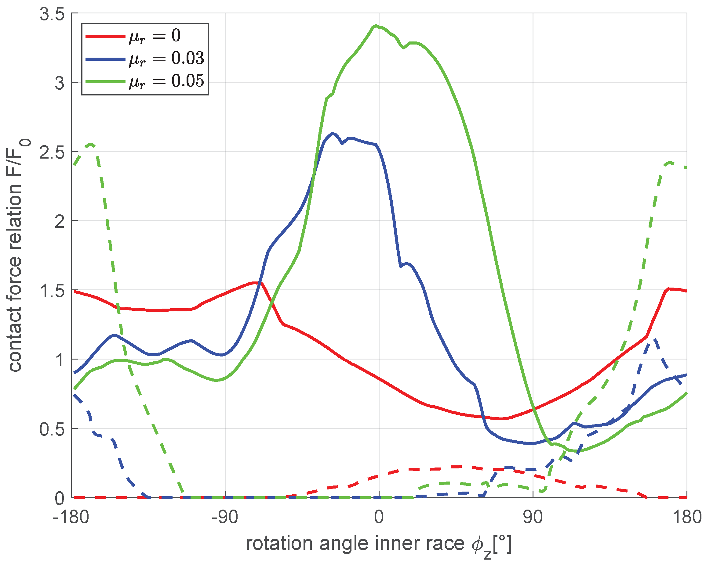
The effect of friction can also be seen when evaluating the contact forces in the tracks and in the cage window. Figure 12 shows the force curves in the track over the angle of rotation of the inner race for different friction coefficients. The contact force on the track flank in the load direction is shown as a solid line, while the contact force on the opposite flank is shown as a dashed line. If the frictional forces are neglected (see red lines in Figure 12), a force curve is established, which, in addition to a relatively constant component, causes a force drop starting at a rotation angle of approximately 70 in the curve of the flank in load direction (solid red line), resulting in a slight increase of the contact force on the counter flank (dashed red line). If the joint is as a consequence operated under bending, a swelling load is generated in the tracks. Taking friction into account (see blue and green lines in Figure 12), this effect is even more pronounced, so that the maximum contact force on both track flanks increases as the coefficient of friction increases. In addition, the maximum contact force in the load flank is shifted in the direction of rotation of the inner race.
The increase in the friction coefficient also has a significant influence on the ball kinematics. As a result of the increasing track force, the portion of the axial force resulting from the track inclination F r e s , β also increases until this axial force component finally becomes larger than F r e s , α of the inclination angle α i n c l (compare Figure 10). Under these circumstances, the ball moves against its preferred direction and contacts the opposite side of the cage window, which does not correspond to the desired kinematics of the joint. Thus, it can be stated that excessive friction in combination with an inclination angle of the tracks has a negative effect on the service life of the joint, since the advantage of low cage forces is negated. For this reason, it is important to be able to predict such an undesired behaviour robustly using a MBS approach, as shown in this paper. The choice of the coefficient of friction of μ r = 0.03 is here based on the expected ball movement in the preferred direction. In addition, this value results in a secondary torque of approximately 3 % of the load torque, which is in line with investigations for double-offset joints with small deflection angles [4].

5. Numerical Analysis of a CVJ

5.1. Ball Kinematics

When designing the joints, the kinematics of the individual balls are of particular interest, since this has a direct effect on the wear behaviour and thus on the efficiency and service life of the system. A detailed description of the ball kinematics with the aid of numerical models offers a suitable potential for performance optimisation and thus for CO2 reduction through the joint by improving material utilisation and efficiency of the overall system.
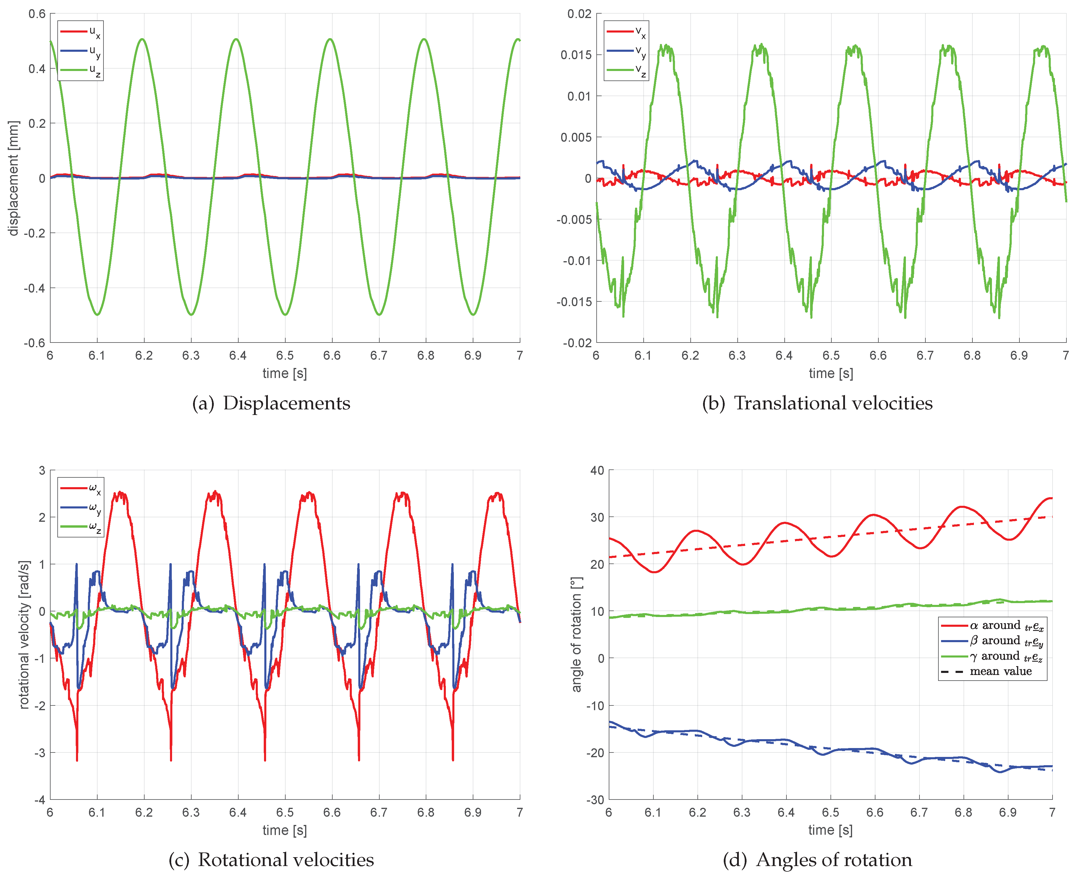
For this purpose, the kinematic curves of the ball were evaluated with respect to the body-fixed track coordinate system   t r e , which rotates with the inner race. Due to the ideal joint geometry in the simulation, the periodic kinematic curves of all eight balls are the same for one revolution of the inner race. They only have a phase shift. For this reason, only one ball is considered in the following. The orientation of the ball at the initial point in time is illustrated in Figure 2. In Figure 13, the curves of the translational displacements of the ball (see Figure 13a), the translational velocities (see Figure 13b), the rotational velocities (see Figure 13c) and the rotational angles of the ball (see Figure 13d) are shown, which result during the rotation at a constant speed of 300 rpm and a load torque of 2000 Nm at a deflection angle of 2 . As a characteristic movement of the ball within the track, the oscillation along the track axis can easily be identified (green curves). Under the given boundary conditions, this results in an oscillation amplitude of displacement of approximately 1 mm (see Figure 13a). In addition, Figure 13a shows ball movements orthogonal to the track axis (red and blue curves). These occur periodically and reach their maximum between the zero position of the ball and its maximum displacement amplitude in the positive direction, which illustrates the cyclical load on the track flank. This movement becomes clearer when looking at the translational speeds in Figure 13b. The maximum absolute speeds orthogonal to the track axis (red and blue curves) occur at the reversal point of the ball (green curve).
For the rotational velocity components, the rotation around the x-axis (red) is dominant, but it is not a pure rolling of the balls along the track axis. Instead, due to the kinematic constraints imposed by the inclined tracks and cage windows, a rolling motion of the ball as a superposition of translational and rotational velocity components can be observed. This becomes clear by evaluating the cardan angles of the ball in Figure 13d. For a pure rolling motion, the angle α around the   t r e x -axis has to oscillate around a constant average value, as it is the case for the ball displacement in z-direction (green curve in Figure 13a). In contrast to this, the rotational angle α around the x-axis (red in Figure 13d) shows a positive drift, which is due to a superimposed rotational movement. In addition to the rotation around the x-axis, a clear velocity component of rotation around the y-axis (blue curve in Figure 13d) can be seen. This indicates a drilling movement of the ball, which can lead to an additional displacement of the lubricant and thus to a reduction in service life due to dry running of the ball in the track. The less harmonic progressions of the rotational velocities are due to the frictional influences and thus to the numerical implementation of the Coulomb’s law used. This could possibly be circumvented by using switching functions, but this would lead to a significant increase in the numerical effort, which is why it is not used in this work, since the focus is on efficiency in order to calculate as many variants as possible in a short computing time.

5.2. Axial Movement

Due to the periodic, alternating track arrangement, the inner race in the CVJ moves axially under deflection during rotation, since a resulting force effect in this direction is produced by the individual track forces. The magnitude of the oscillation that occurs depends on the external load factors. It can be generally stated that it increases proportionally with the deflection angle and rotational speed. For the following analysis, as before, a rotational speed of 300 rpm, a deflection angle of 2 and a load torque of 2000 Nm were used.
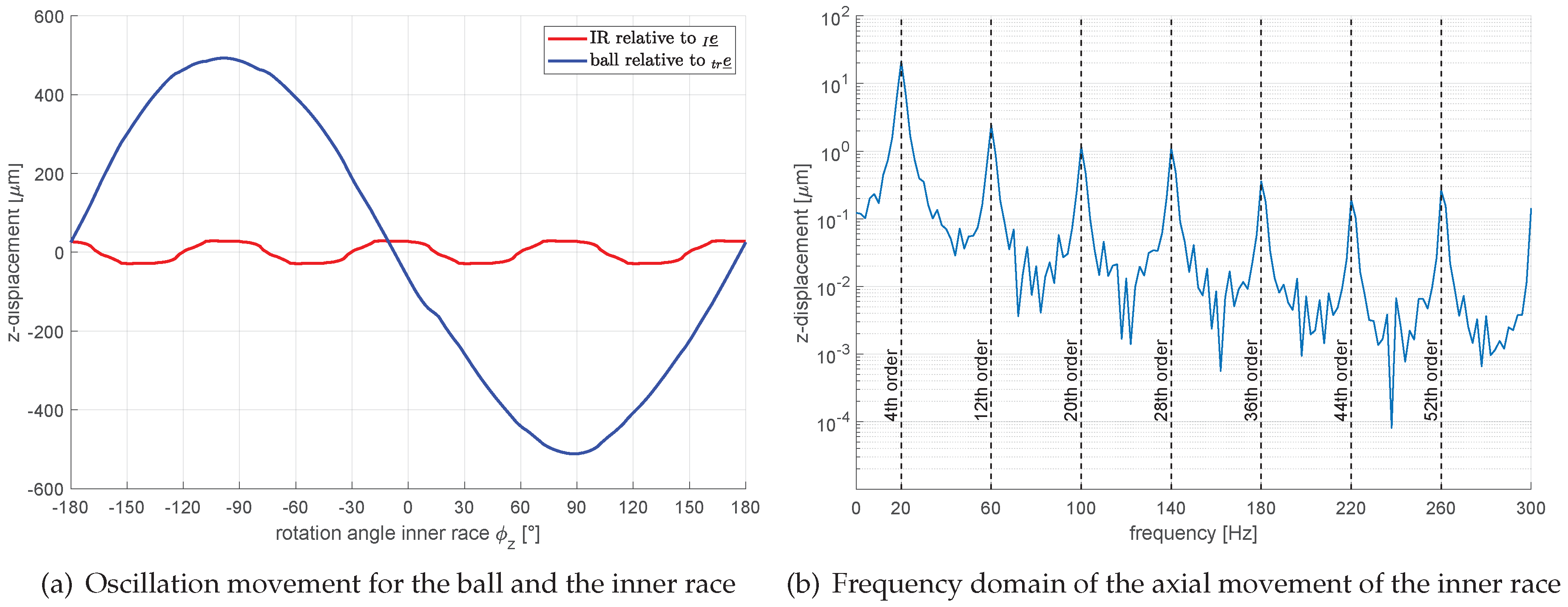
In Figure 14a, the oscillation paths of a ball within the track coordinate system and the inner race with respect to the inertial system are compared. It is noticeable that the inner race, at approximately 58 μ m, has a much smaller oscillating motion than the ball. However, even an initially low amplitude can become critical for the system behaviour in the resonance case, which is why the phenomenon of axial movement in the joint cannot be neglected in the evaluation of the joint. This would not be possible with analytical methods, which underlines the necessity of a numerical joint analysis. It can also be seen that the inner race (red line) performs a four times oscillating movement around the zero position during one revolution.
When transforming the time signal of the axial movement of the inner race via FFT [28] into the frequency domain, the significant frequencies become obvious. The resulting frequency spectrum is shown in Figure 14b. For the rotational speed of 300 rpm, the first order is 5 Hz. As was already evident from the previous time observation of the inner race movement, the fourth order appears to be the most significant frequency of the movement process. This is due to the geometry of the joint (see Figure 1), which has a 90 symmetry due to the alternate track arrangement and the number of balls, so that the joint has an identical starting position after a quarter turn. Further peaks (12th order, 20th order, 28th order, etc.; see Figure 14b) occur starting from the fourth order in addition to an integer multiple of the number of balls (eight). The characteristic frequencies of the axial excitation of the inner race thus depend exclusively on the existing CVJ geometry in form of the track arrangement and the number of balls used. When using the joint, the frequencies occurring in the drive train should therefore be balanced with those of the axial excitation in the CVJ in order to prevent possible resonance cases. In addition to the reduction of associated NVH conspicuous features, this also leads to a lower stress on the joint and thus to an optimisation of running time and a more application-oriented design.

6. Conclusions

In the present work, a multi-body simulation model for analysing the kinematics and the acting forces within a constant velocity joint (CVJ) is presented. The plunging joint has straight tracks with an elliptical cross-section and two track angles per track, so that an analytical contact determination is possible between balls and tracks as well as between balls and cage.
The verification of the CVJ with regard to the homokinetic condition to be fulfilled showed that a significantly higher contact stiffness must be selected than that provided by Hertzian contact theory. This deviation is caused by a relatively large contact area between ball and track with respect to the ball surface. The resulting contact forces were compared for benchmark problems with analytical calculation results and generally showed good agreement. It is noticeable that the cage does not absorb forces for low load torques, since these forces are initially absorbed completely by the track. This can be attributed to the high contact stiffness which was chosen to sufficiently fulfil the homokinetic condition with the analytical approach. Moreover, a clear influence of the friction coefficient on the joint kinematics and the contact forces can be observed, which is shown by the example of the secondary torque.
By analysing the ball kinematics and the axial movement in the joint, two examples of usage possibilities of the simulation model are shown. By evaluating the kinematic pathways of the ball, a pure rolling motion of the balls within the track can be excluded. Furthermore, possible NVH influences caused by an axial movement of the inner race can be determined for deflected joint condition, which depend on the application parameters and the joint geometry. In this way, the presented model can be integrated into the development process in addition to analytical methods in order to take into account transient processes and dynamic effects. Finally, the model allows parameter studies for the influence analysis of individual joint parameters on the kinematics, which reduces the scope of real test bench investigations.
In further studies, the contact stiffness in the joint should be validated in test bench investigations by examining the influence of the joint geometry on the fulfilment of the homokinetic condition. In addition, it should be investigated whether another contact model for the contact determination such as a surface model possibly fulfils the homokinetic condition at lower contact stiffnesses. If it is necessary to detail the model at this point, this is accompanied by a significant increase in the numerical effort, whereby the additional effort must be put in proportion to the actual refinement of the calculation results. Supplementarily, it would be useful to measure the analysed forces and kinematics so that the simulation results can be validated. For this purpose, both direct measurement of the contact forces and measurement of the secondary torque are suitable for determining the friction coefficient in the joint tracks. To increase the level of detail of the multi-body simulation, it is also conceivable to make the joint components such as the cage or inner ring elastic. In this way, further influences on the joint kinematics can be investigated. Furthermore, a more precise description of the friction behaviour between ball and track could also be helpful r to characterise the joint behaviour even more precisely in future.
Author Contributions

The basis of the multibody simulation program used in this work was developed by C.D. and E.W. and extended by P.M. to perform a numerical modeling of a CVJ. C.D. and P.M. have programmed the necessary force element and performed the numerical simulations. The article is mainly written by P.M., while both theoretical background as well as for the writing, discussions and comments provided by F.D. and E.W. were essential for the quality of the work. All authors have read and agreed to the published version of the manuscript.

Funding

This research received no external funding.

Acknowledgments

The presented work was developed in close cooperation with IFA Technologies GmbH in Haldensleben. This support is gratefully acknowledged. Special thanks goes to Guido Kuhlemann and David Schmicker of IFA Technologies GmbH for their helpful comments and suggestions.

Conflicts of Interest

The authors declare no conflict of interest.

Abbreviations

The following abbreviations are used in this manuscript:
CVJConstant velocity joint
DAEDifferential algebraic equations
DOJDouble offset joint
NVHNoise, Vibration and Harshness
ODEOrdinary differential equations
PCDPitch circle diameter

References

  1. Hayama, Y. Dynamic Analysis of Forces Generated on Inner Parts of a Double Offset Constant Velocity Universal Joint (DOJ): Non-Friction Analysis; SAE Technical Paper Series; SAE International400 Commonwealth Drive; SAE: Warrendale, PA, USA, 2001. [Google Scholar] [CrossRef]
  2. Kimata, K.; Nagatani, H.; Imoto, M.; Kohara, T. Numerical Analyses and Experiments on the Characteristics of Ball-Type Constant-Velocity Joints. JSME Int. J. Ser. C 2004, 47, 746–754. [Google Scholar] [CrossRef] [Green Version]
  3. Kimata, K.; Nagatani, H.; Imoto, M. Analysis of Ball-Type Constant-Velocity Joints Based on Dynamics. JSME Int. J. Ser. C 2004, 47, 736–745. [Google Scholar] [CrossRef] [Green Version]
  4. Serveto, S.; Mariot, J.P.; Diaby, M. Secondary Torque in Automotive Drive Shaft Ball Joints: Influence of Geometry and Friction. Proc. Inst. Mech. Eng. Part K J. Multi-Body Dyn. 2008, 222, 215–227. [Google Scholar] [CrossRef]
  5. Lim, Y.H.; Song, M.E.; Lee, W.H.; Cho, H.J.; Bae, D.S. Multibody dynamics analysis of the driveshaft coupling of the ball and tripod types of constant velocity joints. Multibody Syst. Dyn. 2009, 22, 145–162. [Google Scholar] [CrossRef]
  6. Ascher, U.M.; Petzold, L.R. Computer Methods for Ordinary Differential Equations and Differential-Algebraic Equations; Society for Industrial and Applied Mathematics: Philadelphia, PA, USA, 1998. [Google Scholar]
  7. Pennestrì, E.; Valentini, P.P. Kinematic design and multi-body analysis of Rzeppa pilot-lever joint. Proc. Inst. Mech. Eng. Part K J. Multi-Body Dyn. 2008, 222, 135–142. [Google Scholar] [CrossRef]
  8. Valentini, P.P. Effects of the dimensional and geometrical tolerances on the kinematic and dynamic performances of the Rzeppa ball joint. Proc. Inst. Mech. Eng. Part D J. Automob. Eng. 2014, 228, 37–49. [Google Scholar] [CrossRef]
  9. Pennestrì, E.; Rossi, V.; Salvini, P.; Valentini, P.P.; Pulvirenti, F. Review and kinematics of Rzeppa-type homokinetic joints with straight crossed tracks. Mech. Mach. Theory 2015, 90, 142–161. [Google Scholar] [CrossRef]
  10. Shen, L.J. Multibody contact simulation of constant velocity plunging joint. Mitteilungen aus dem Institut für Maschinenwesen der Technischen Universität Clausthal 2010, 35, 95–101. [Google Scholar]
  11. Hippmann, G. Modelling of Contacts of Complex Shaped Bodies in Multibody Dynamics (German). Ph.D. Thesis, Technical University of Vienna, Vienna, Austria, 2004. [Google Scholar]
  12. Seherr-Thoss, H.C.; Schmelz, F.; Aucktor, E. Universal Joints and Driveshafts: Analysis, Design, Applications, 2nd ed.; Springer: New York, NY, USA, 2006. [Google Scholar]
  13. Daniel, C. Simulation of Plain and Roller Bearing Systems Based on a Multi-Body System for Rotordynamic Applications (German). Ph.D. Thesis, Otto-von-Guericke University, Magdeburg, Germany, 2013. [Google Scholar]
  14. Schwertassek, R.; Wallrapp, O. Dynamics of Flexible Multibody Systems (German); Vieweg+Teubner Verlag: Wiesbaden, Germany, 1999. [Google Scholar] [CrossRef]
  15. Wallrapp, O. Standardization of Flexible Body Modeling in Multibody System Codes, Part I: Definition of Standard Input Data. Mech. Struct. Mach. 1994, 22, 283–304. [Google Scholar] [CrossRef]
  16. Woernle, C. Multibody Systems: An Introduction to the Kinematics and Dynamics of Rigid Body Systems (German), 2nd ed.; Springer: Berlin, Germany, 2017. [Google Scholar]
  17. Gipser, M. Systemdynamics and -Simulation (German); Vieweg+Teubner Verlag: Wiesbaden, Germany, 1999. [Google Scholar] [CrossRef]
  18. Atkinson, K.; Han, W.; Stewart, D.E. Numerical Solution of Ordinary Differential Equations; Pure and Applied Mathematics; Wiley: Chicester, UK, 2011. [Google Scholar]
  19. Hertz, H. Über die Berührung fester elastischer Körper. J. Für Die Reine Und Angew. Math. 1882, 92, 156–171. [Google Scholar]
  20. Johnson, K.L. One Hundred Years of Hertz Contact. Proc. Inst. Mech. Eng. 1982, 196, 363–378. [Google Scholar] [CrossRef]
  21. Hunt, K.H.; Crossley, F.R.E. Coefficient of Restitution Interpreted as Damping in Vibroimpact. J. Appl. Mech. 1975, 42, 440–445. [Google Scholar] [CrossRef]
  22. Hamrock, B.J.; Brewe, D. Simplified Solution for Stresses and Deformations. J. Lubr. Technol. 1983, 105, 171–177. [Google Scholar] [CrossRef]
  23. Popov, V.L. Contact Mechanics and Friction: Physical Principles and Applications; Springer: Heidelberg, Germany; New York, NY, USA, 2010. [Google Scholar]
  24. Fritz, F. Modelling of Rolling Bearings as Generic Machine Elements of a Multibody Simulation (German): Zugl. Ph.D. Thesis, Karlsruhe Institute of Technology (KIT), Karlsruhe, Germany, 2011. [Google Scholar]
  25. Marter, P. Development of a Simulation Model for the Analysis of Rolling Element Kinematics and Dynamics in Constant Velocity Ball Joints under General, Transient Operating Conditions (German). Master’s Thesis, Otto-von-Guericke University, Magdeburg, Germany, 2020. [Google Scholar]
  26. Orain, M. General Theory and Experiment of Homokinetic Joints. Ph.D. Thesis, Université Pierre et Marie Curie, Paris, France, 1979. [Google Scholar]
  27. Kudra, G.; Awrejcewicz, J. Approximate modelling of resulting dry friction forces and rolling resistance for elliptic contact shape. Eur. J. Mech. A/Solids 2013, 42, 358–375. [Google Scholar] [CrossRef]
  28. Cooley, J.W.; Lewis, P.; Welch, P.D. The fast Fourier transform algorithm: Programming considerations in the calculation of sine, cosine and Laplace transforms. J. Sound Vib. 1970, 12, 315–337. [Google Scholar] [CrossRef]
Figure 1. Components of a CVJ.
Applsci 10 03715 g001
Figure 2. Position of an exemplary track coordinate system and the contact plane using the example of the inner race: (left) spatial presentation; and (right) top view.
Applsci 10 03715 g002
Figure 3. Analytical contact determination for the ball: red, ball; blue, track; and green, cage.
Applsci 10 03715 g003
Figure 4. Elastic deformation of exemplary contact bodies as a result of the Hertzian contact force F N , e l according to Fritz [24].
Applsci 10 03715 g004
Figure 5. Coulomb friction coefficient for different functional relationships μ = f ( v t ) .
Applsci 10 03715 g005
Figure 6. Homokinetic condition: The balls and the cage are in the bisecting plane between outer race and inner race for each deflection angle β b a .
Applsci 10 03715 g006
Figure 7. Cage deflection angle at different load torques for several equivalent contact stiffnesses K e q v .
Applsci 10 03715 g007
Figure 8. Verification of the contact forces by analytical results.
Applsci 10 03715 g008
Figure 9. Calculation of the analytical contact force.
Applsci 10 03715 g009
Figure 10. Forces acting on the ball due to the inclination angles α i n c l and β i n c l and the cage.
Applsci 10 03715 g010
Figure 11. Secondary torque at 2 deflection angle and a load torque of 2000 Nm for different friction coefficients.
Applsci 10 03715 g011
Figure 12. Track contact forces using different friction coefficients: solid line, track flank in load direction; dashed line, counter track flank (opposite load direction); and contact force relation F / F 0 , track force F related to F 0 for undeflected joint condition.
Applsci 10 03715 g012
Figure 13. Kinematic pathways of the ball in the track of the inner race.
Applsci 10 03715 g013
Figure 14. Axial movement of the inner race.
Applsci 10 03715 g014