Abstract
In the paper a model is developed for a proposed eddy current damper using finite element analysis. Several damper configurations are studied and its characteristics are analyzed. The steady state performance for the configurations is compared to reach a design with an acceptable performance for the eddy current damper. Furthermore, the proposed designs performance are compared with the traditional damper performance. It was found that the best two designs to achieve the targeted performance were to have an iron core damper or an iron core with an aluminum sleeve. Those two designs are economical and simple while achieving acceptable performance when compared to traditional dampers and other electromagnetic damping systems.
1. Introduction
It is well known that automotive shock absorbers represent the main part of suspension systems responsible for reducing effects of road bumps and, consequently, isolating the frame of the vehicle from driveway disturbances. It turns out that traditionally employed shock absorbers are comprised of hydraulic cylinders, where smoothing bump effects result in heat generation. This fact in addition to the potential of viscous fluid leakage represents an environmental hazard.
In the past years, electromagnetic suspension systems (EMSs) emerged as an alternative to conventional hydraulic shock absorbers. Common EMSs are either categorized as tubular electromagnetic actuator systems or eddy current systems. Both exhibit smaller response time and wider effective bandwidth in comparison to conventional hydraulic shock absorber systems. For the case of eddy current EMSs, eddy currents due to permanent magnets are induced in the moving part of the EMS and, consequently, an opposing electromagnetic force proportional to the vertical motion velocity is created. This action replicates that of a viscous damper. It should be mentioned here that the application of an eddy currents damping effect has been previously investigated for the purpose of magnetic braking and vibration attenuation in mechanical structures [1,2,3,4,5,6].
Several efforts have been recently carried out to analyze as well as optimize EMS configurations (see, for instance, [7]). Examples include the investigation of a dynamic model for an eddy current damper (ECD) in [8] and the formulation of an improved and more accurate theoretical model of ECD system in [9]. Moreover, novel ECD configurations have been also introduced recently [10,11,12,13,14,15,16]. Those studies clearly highlight the main advantages of ECDs. Such advantages include the lack of need of any power source, reliability, durability, and environmentally non-hazardous. The effect of inserting aluminum layer around the iron actuator was studied in [17]. It was found that the aluminum layer increases the damping force while decreasing the weight of the damper. Furthermore, an optimum thickness for the aluminum layer that produces the best performance has been reached.
In this paper, a model is developed for a proposed eddy current damper using finite element analysis. Several damper configurations are studied and its characteristics are analyzed. The steady state performance for the configurations is compared to reach a design with an acceptable performance for the eddy current damper. The damping force magnitude for the several proposed designs is examined. The steady state performance of the damper designs was also discussed. It was found that the best two designs to achieve the targeted performance were to have an iron core damper or an iron core with an aluminum sleeve. Those two designs are economical and simple while achieving acceptable performance when compared to traditional dampers and other electromagnetic damping systems.
2. Materials and Methods
2.1. Construction and Materials
The components of the traditional shock absorber are the spring and the hydraulic damper, this passive suspension system keeps the car balanced by converting the kinetic energy gained by disturbance into heat due to the internal pressurized oil passing through orifices [18]. In the proposed model the eddy current damper will be added to the traditional damper, giving higher damping force and better suspension performance.
Figure 1 shows the construction of the eddy current damper with the four configurations studied. The first configuration is with six magnets with an iron actuator with no aluminum sleeve, the second one an aluminum sleeve is inserted around the iron actuator, the third one the six magnets are divided into two groups with reversed polarity, while the fourth configuration is with four magnets. The permanent magnets axially-magnetized are fixed to the stator. The NdFeB kind is used due to its high magnetic flux density in addition to its low mass. The four models’ dimensions are listed in Table 1.

Figure 1.
Axisymmetric view for the eddy current damper configurations: (a) Model I, (b) Model II, (c) Model III, (d) Model IV.

Table 1.
Model dimensions.
2.2. Electromagnetic Simulation of ECD
To attain the best design parameters, the system should be analyzed using finite element modeling (FEM). A 2D axisymmetric model was analyzed by using a simulation software package.
As shown in Equation (1), the induced current density (J) depends on three factors, first conductivity of medium (σ), second the relative vertical velocity between the stator and the actuator (ν), and the flux density (B). Thus, a higher relative velocity results in more intense induced eddy currents. The interaction between the induced current density and the magnetic flux density will produce Lorentz force , which will act as a damping force [10].
where V is the medium volume.
It can be seen from Equation (2) that the damping force increases as the quantities (J) and (B) increase. According to Lenz’s rule, the magnetic field produced from the induced eddy current will oppose the change in the original field which causes it. Thus the induced field will oppose the direction of motion of the actuator and acts as linear viscous damper [11].
2.3. Quarter-Car Model
The quarter-car model is considered a good representation for the vehicle suspension system. The full-car model is more accurate to evaluate the performance of the suspension system; however, the quarter-car model will be used for simplicity also it allows to compare between the behavior of the system before the effect of the eddy current damper and after modification [19,20]. As shown in Figure 2, there are two vertical degrees of freedom for sprung and un-sprung masses (m1, m2). The model parameters are listed in Table 2.
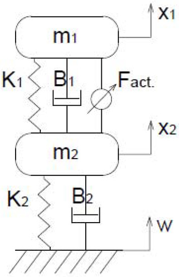
Figure 2.
Quarter car suspension model with Eddy Current Damper [17].
Table 2.
Mechanical suspension parameters.
Through the quarter-car model the suspension system could be expressed by the following equations:
Equations (3) and (4) may be solved considering that the system was subjected to a step road disturbance. It should be noted that the road disturbance could be step or gradual, but the step disturbance was chosen since it causes the most extreme disturbance. The system was modelled using Matlab as shown in Figure 3. Table 2 shows the input parameter for the system. In order to show the effect of the eddy current damper on the suspension system, a Simulink model was used to solve the equations without the ECD force, then it was solved again after adding the term () which represent the added damping force. The system dynamic behavior in the two cases, for the four configurations, will be compared to show the improvement that happened in the system response, which leads to more car balance and more comfort ride.
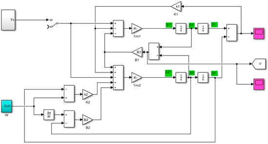
Figure 3.
MATLAB/Simulink model [17].
3. Results
3.1. Force Calculations from the FEM Model
In order to obtain the performance of the ECD, the average force at each velocity is calculated from the FEM model. A relation between the force and the velocity is then obtained. As previously explained, the force depends on the magnetic flux density and the induced eddy currents.
Figure 4, Figure 5, Figure 6 and Figure 7 show the magnetic flux density and the induced current density for the four models at a linear speed of 1 m/s.
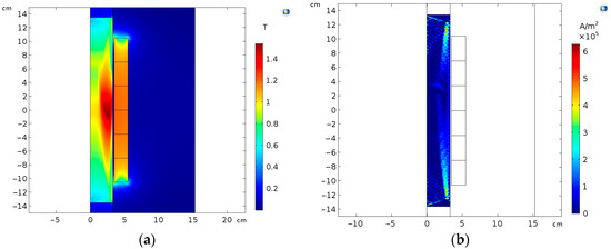
Figure 4.
For Model I: (a) Magnetic flux density, (b) induced current density, at v = 1.0 m/s.
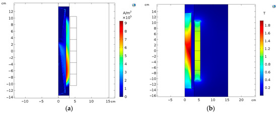
Figure 5.
For Model II: (a) Magnetic flux density, (b) induced current density, at v = 1.0 m/s.
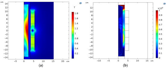
Figure 6.
For Model III: (a) Magnetic flux density, (b) induced current density, at v = 1.0 m/s.
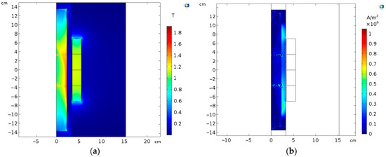
Figure 7.
For Model IV: (a) Magnetic flux density, (b) induced current density, at v = 1.0 m/s.
It can be observed from the figures that while the magnetic flux density is high in model I due to the absence of the aluminum layer, the induced current density is relatively low due to the low conductivity of iron compared to aluminum. In model II, the presence of the aluminum layer increased the induced current density, which will reflect in an increased damping force. In model III, the induced current density is low and non-uniform on the actuator resulting in a lower damping force. Furthermore, the induced current density is also low in model IV since the number of magnets is reduced.
Figure 8 shows the damping force profile for the four configuration. It can be observed that the highest damping force is exerted in models I and II. Using curve fitting, the four above relations were expressed as third degree polynomials and were inserted in the Simulink model to obtain the response of the quarter-car model to a step road disturbance.
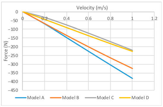
Figure 8.
The damping force profiles for the four proposed design cases.
3.2. Quarter-Car Model Response
Figure 9, Figure 10 and Figure 11 shows the dynamic response for the quarter-car model with no ECD compared with the different ECD models that were proposed.
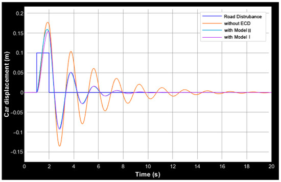
Figure 9.
Comparison between the suspension displacement response during road disturbance, between Models I and II.
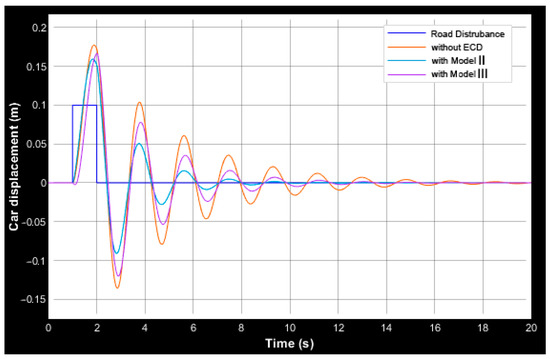
Figure 10.
Comparison between the suspension displacement response during road disturbance, between Models II and III.

Figure 11.
Comparison between the suspension displacement response during road disturbance, between Models II and IV.
It can be noticed that Models I and II provide an acceptable response compared to the other models. Both designs gave a similar displacement response after facing a step disturbance. For Models I and II, the vehicle was restored to a steady-state in less than 10 s, while the two other models took 2 to 3 s longer to reach a steady-state. Additionally, the maximum overshoot for Models I and II is less than Models III and IV, which provides a more comfortable first response to the road disturbance.
4. Discussion
If we compared the best two models with the traditional hydraulic damper, it can be found that Model II, which has the aluminum sleeve, is preferable due to lower weight, thus lower cost. The comparison is shown in Table 3.
Table 3.
Comparison between the specifications of traditional damper, Model I, and Model II.
5. Conclusions
This paper studied the performance of an eddy current damper for four different models using finite element analysis. It was found that the design with the most acceptable performance and the most economical design, is the one with an aluminum sleeve around its iron actuator. The steady state response at different cases were examined. The best design was evaluated at different frequencies. The proposed system is economical and simple compared to other electromagnetic damping systems.
Author Contributions
Conceptualization, A.A.A. (Amr A. Adly), T.M.A. and A.A.H.; methodology, A.A.A. (Amr A. Adly), T.M.A. and A.A.H.; software, A.A.A. (Ahmed A. Abdallah), T.M.A.; validation, A.A.A. (Ahmed A. Abdallah), T.M.A.; formal analysis, A.A.A. (Ahmed A. Abdallah), T.M.A.; investigation, A.A.A. (Ahmed A. Abdallah), T.M.A.; resources, A.A.A. (Ahmed A. Abdallah), T.M.A.; data curation, A.A.A. (Ahmed A. Abdallah), T.M.A.; writing—original draft preparation, A.A.A. (Ahmed A. Abdallah), T.M.A.; writing—review and editing, A.A.A. (Ahmed A. Abdallah), T.M.A. and A.A.H.; visualization, A.A.A. (Ahmed A. Abdallah); supervision, A.A.A. (Amr A. Adly), T.M.A. and A.A.H.
Funding
This research received no external funding.
Conflicts of Interest
The authors declare no conflicts of interest.
References
- Wiederick, H.D.; Gauthier, N.; Campbell, D.A.; Rochon, P. Magnetic braking: Simple theory and experiment. Am. J. Phys. 1987, 55, 500–503. [Google Scholar] [CrossRef]
- Ma, D.-M.; Shiau, J.-K. The design of eddy-current magnet brakes. Trans. Can. Soc. Mech. Eng. 2011, 35. [Google Scholar] [CrossRef]
- Adly, A.A.; Abd-El-Hafiz, S.K. Speed Range Based Optimization of Non-linear Electromagnetic Braking Systems. IEEE Trans. Magn. 2007, 43, 2606–2608. [Google Scholar] [CrossRef]
- Saxena, A.; Patel, R.K. Vibration control of cantilever beam using Eddy Current Damper. Int. J. Eng. Sci. Innov. Technol. (IJESIT) 2013, 2. [Google Scholar]
- Bae, J.; Hwang, J.; Kwag, D.; Park, J.; Inman, D.J. Vibration Suppression of a Large Beam Structure Using Tuned Mass Damper and Eddy Current Damping. Shock Vib. 2014, 2014, 893914. [Google Scholar] [CrossRef]
- Singh, R.; Sharma, M.; Singh, V.P. An Experimental Study of Vibration Control of Cantilever Beam Using Eddy Current Damper. Int. J. Appl. Eng. Res. 2012, 7. [Google Scholar]
- Graves, K.E.; Tonicich, D.; Iovenitti, P.G. Theoretical comparison of motional and transformer EMF device damping efficiency. J. Sound Vib. 2012, 233, 441–453. [Google Scholar] [CrossRef]
- Tonoli, A. Dynamic characteristics of eddy current dampers and couplers. J. Sound Vib. 2007, 301, 576–591. [Google Scholar] [CrossRef]
- Sodano, H.A.; Bae, J.-S.; Inman, D.J.; Belvin, W.K. Improved Concept and Model of Eddy Current Damper. J. Vib. Acoust. 2005, 128, 294–302. [Google Scholar] [CrossRef]
- Ebrahimi, B.; Khamesee, M.B.; Golnaraghi, M.F. Design and modeling of a magnetic shock absorber based on eddy current damping effect. J. Sound Vib. 2008, 315, 875–889. [Google Scholar] [CrossRef]
- Bae, J.-S.; Hwang, J.-H.; Park, J.-S.; Kwag, D.-G. Modeling and experiments on eddy current damping caused by a permanent magnet in a conductive tube. J. Mech. Sci. Technol. 2009, 23, 3024–3035. [Google Scholar] [CrossRef]
- Ebrahimi, B.; Khamesee, M.B.; Golnaraghi, F. Eddy current damper feasibility in automobile suspension: Modeling, simulation and testing. Smart Mater. Struct. 2009, 18. [Google Scholar] [CrossRef]
- Kim, S.-W.; Jung, H.-K.; Hahn, S.-Y. Experimental Study for Dynamic Characteristics of Eddy Current Shock Absorber. J. Korean Soc. Aeronaut. Space Sci. 2007, 35, 1089–1094. [Google Scholar]
- Guo, L.; Guo, N.; Wang, S.; Qiu, J.; Zhu, J.G.; Guo, Y.; Wang, Y. Performance of hybrid electromagnetic damper for vehicle suspension. Int. J. Innov. Eng. Res. Technol. 2015, 2. [Google Scholar]
- Adly, A.A.; Abd-El-Hafiz, S.K. Active electromagnetic suspension system design using hybrid neural-swarm optimization. Int. J. Appl. Electromagn. Mech. 2013, 43, 85–91. [Google Scholar] [CrossRef]
- Adly, A.A.; Adly, M.A. Utilizing Electromechanical Energy Harvesting in Vehicle Suspension Vibration Damping. In Proceedings of the 23rd IEEE International Conference on Electronics, Circuits and Systems (ICECS), Monte Carlo, Monaco, 11–14 December 2016; pp. 672–675. [Google Scholar]
- Abdullah, A.A.; Abdo, T.M.; Huzayyin, A.A.; Adly, A.A. Performance Analysis of Eddy Current Shock Absorber Damper Using Finite Element Analysis. In Proceedings of the 19th International Middle-East Power Systems Conference (MEPCON 2017), Cairo, Egypt, 19–21 December 2017. [Google Scholar]
- Paulides, J.J.H.; Encica, L.; Lomonova, E.A.; Vandenput, A.J.A. Design Considerations for a Semi-Active Electromagnetic Suspension System. IEEE Trans. Magn. 2006, 42, 3446–3448. [Google Scholar] [CrossRef]
- Gysen, B.L.J.; Paulides, J.J.H.; Lomonova, E.A. Active Electromagnetic Suspension System for Improved Vehicle Dynamics. IEEE Trans. Veh. Technol. 2010, 59, 1156–1163. [Google Scholar] [CrossRef]
- Grant, A.M. Analysis of Automotive Damper Data and Design of a Portable Measurement System. Ph.D. Thesis, The Ohio State University, Department of Mechanical Engineering, Center for Automotive Research, Columbus, OH, USA, 2005. [Google Scholar]
© 2019 by the authors. Licensee MDPI, Basel, Switzerland. This article is an open access article distributed under the terms and conditions of the Creative Commons Attribution (CC BY) license (http://creativecommons.org/licenses/by/4.0/).