Abstract
Wall-climbing robots have broad application potential in industrial equipment inspection, chemical storage tank maintenance, and high-altitude operations. However, their practical implementation is challenged by the robots’ adhesion requirements in complex wall environments. This study uses a systematic methodology integrating computational simulation and experimental validation to design and optimize a magnetic adsorption system for wall-climbing robots. Firstly, an adjustable suspended magnetic adhesion unit is designed to achieve intelligent control of a wall-climbing robot’s adhesion force on a wall surface. The Maxwell software (AnsysEM21.1) is used to simulate and analyze the critical parameters of the magnetic adsorption unit, including the thickness of the magnet and yoke, as well as the distance and angle between the magnet and the wall surface. Then, a magnetic wheel is designed for the wall-climbing robot based on the optimization of the structure and parameters of the magnetic adhesion unit. The absorption and demagnetization of the magnetic wheels are achieved by rotating the magnetic absorption unit. Subsequently, the simulation results are verified on the experimental platform, and adhesion performance tests are conducted on both standard flat surfaces and inclined walls. The results show that the optimized single magnetic adhesion unit gives the wall-climbing robot an adhesion force of 2767 N under normal working conditions, with a simulation experiment error margin as low as 8.3%. These results both provide theoretical guidance and highlight practical methodologies for developing high-performance magnetic adsorption systems in complex operational environments.
1. Introduction
In modern industrial maintenance and operation, specialized robotic solutions, such as disaster response robots and automated inspection robots, have emerged as pivotal enablers of technological innovation and operational efficiency enhancement. As a critical branch of special robotic technologies, wall-climbing robots demonstrate extensive deployment potential across petrochemical facilities, marine engineering applications, and infrastructure maintenance sectors [1,2,3]. These robotic platforms integrate multifunctional modules such as automated rust-removal systems and intelligent weld inspection units, enabling safe and effective task execution in hazardous, inaccessible, or otherwise challenging environments [4]. Through the displacement of manual labor in high-risk scenarios, such implementations significantly mitigate occupational hazards while achieving measurable improvements in workforce productivity [5].
Adhesion is a critical determinant for ensuring the operational stability of wall-climbing robots. Excellent adhesion characteristics not only ensure stable adhesion of robots on different types of wall surfaces but also enable them to effectively cope with complex working environments, such as vertical, inclined, and curved surfaces, under various conditions. The choice of adhesion method directly affects a robot’s mobility, load-bearing capacity, and operational efficiency. When wall-climbing robots perform tasks such as high-altitude operations, inspections, and maintenance, the quality of their adhesion performance determines whether they can complete these tasks safely and efficiently. Therefore, optimizing the adhesion method and enhancing adhesion are important directions in the research and development of wall-climbing robot technology. Currently, wall-climbing robots mainly use three adsorption methods: negative-pressure adsorption, biomimetic adsorption, and magnetic adsorption [6,7]. Among them, while the principle of negative-pressure adhesion is simple, its energy consumption during continuous adhesion–detachment cycles is high, which significantly limits the robot’s mobility [8]. Bionic adsorption is mainly based on imitating the adhesion principles of the feet of natural organisms, including grasping methods based on claw-like structures [9,10] and adhesion methods based on van der Waals forces generated between microstructures and the contact surface [11]. It is suitable for rough surfaces but gives the robot a relatively slow movement speed and low load capacity [12]. In contrast, permanent magnet adsorption has strong adhesion, low power consumption, and high working stability [13,14], and this technology has been extensively studied by scholars due to its stability and reliability [15,16]. Wall-climbing robots applied to steel walls mainly include tracked robots and wheeled robots [17]. C. Park et al. designed and produced a modular wall-climbing robot, R-Track [18], that can be separated into pairs. R-Track consists of three tracked wall-climbing robots, and each module is connected with a magnetic connector to enable transitions between vertical walls, but it does not have sufficient load capacity to carry the working module. Kosuke Nagaya et al. designed a tracked vehicle that can crawl on surfaces with small curvatures [19], but it cannot transition between different walls. Although wall-climbing robots with permanent magnet wheels are flexible, there is a small contact area between their wheels and the wall, resulting in weaker magnetic adhesion [20]. Moreover, the contact-type magnetic attraction mechanism cannot actively adjust the attraction force and may experience wear.
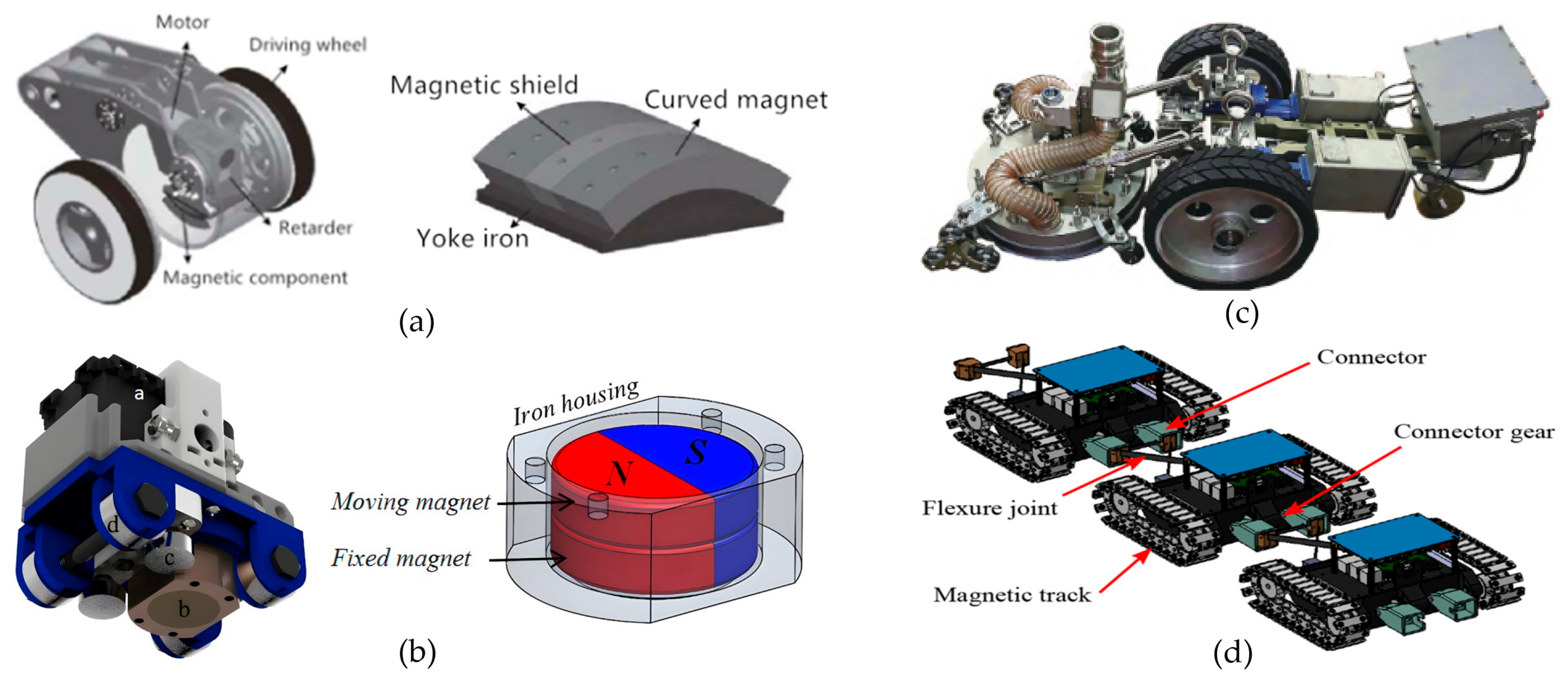
Figure 1 presents four different types of wall-climbing robots and their key design features. Figure 1a shows a wall-climbing robot developed by Zhejiang University [21], where the magnetic adhesion assembly is placed beneath the reducer in conjunction with a yoke iron to enhance the overall magnetic performance. This robot adopts curved permanent magnets and a Halbach array, thereby reinforcing the internal residual magnetic field and mitigating external magnetic interference. Although the system is compact and portable, its load capacity is limited, making it unsuitable for more complex tasks. Figure 1b illustrates a permanent-magnet-based wall-cleaning robot developed in 2022 by the Shenzhen Institute of Advanced Technology, Chinese Academy of Sciences, with separate front-end cleaning and rear-end driving modules [22]. Planetary wheels are installed at the front end to achieve smoother wall transitions. However, during these transitions, the adsorption device must frequently attach and detach, resulting in relatively slow overall movement. Figure 1c depicts an inchworm-inspired climbing robot proposed by José Carlos Romão and colleagues, which employs switchable magnets but still relies on traditional permanent-magnet adsorption, thus limiting its adaptability to various wall conditions [23]. Figure 1d presents the R-Track robot, which utilizes a separable modular system but requires at least two or more modules to cooperate when transitioning between external walls. The robot utilizes redundancy design and dynamic reconfiguration of components, enabling the system to adjust its structure and functions during operation as needed to handle varying workloads and environmental changes [24]. The four wall-climbing robots described above each possess unique characteristics in terms of their magnetic adhesion mechanisms, structural design, and functional orientation, demonstrating their respective advantages and limitations in various application scenarios. Our research presents an innovative adhesion method and structural design that balances high load capacity, maneuverability, and multi-scenario adaptability, providing a more competitive solution for efficient operations in complex environments.

Figure 1.
Four different wall-climbing robots, (a) Zhejiang University wall-climbing robot; (b) Permanent-magnet-based wall-cleaning robot; (c) Inchworm-inspired climbing robot; (d) R-Track robot.
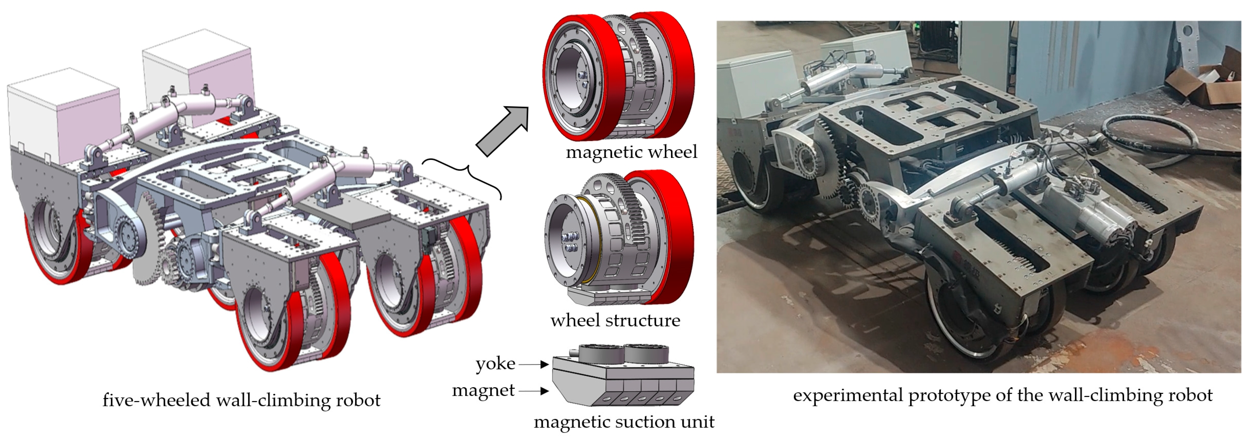
A wall-climbing robot’s adsorption capabilities predominantly hinge on the performance of its magnetic attraction unit. The quality of the unit’s design is a determining factor for a robot’s stability and operational efficiency across different wall surfaces. Therefore, in-depth design parameter research, simulation analyses, and experimental verification of magnetic attraction units are crucial for promoting the advancement of wall-climbing robot technology. This study designs a swinging magnetic adhesion mechanism and adjustable connectors to optimize the angle and distance between the magnetic adhesion unit and the wall. Meanwhile, it proposes a method for optimizing the design parameters of magnetic adsorption units, and through a combination of simulations and experiments, it verifies the stability of wall transitions and load adhesion. Figure 2 presents our five-wheeled wall-climbing robot with some of its magnetic adhesion units labeled; there is one magnetic adhesion unit in each of the five wheels. The rest of this paper is organized as follows. Section 2 discusses the design and simulation analysis of the magnetic adhesion unit, including the key design parameters such as the magnet and yoke thickness, as well as the effects of the distance and angle between the adhesion unit and the wall. Section 3 introduces the magnetic attraction wheel, an important component of the wall-climbing robot. Section 4 presents the experimental validation, comparing the simulation results with the actual results of test conducted on various surfaces. Finally, Section 5 presents our conclusions and discusses future work that can be conducted to further optimize the magnetic attraction system of the wall-climbing robot and enhance its performance in complex environments.
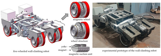
Figure 2.
Five-wheeled wall-climbing robot and magnetic adhesion units.
2. Simulation Analysis of Structural Parameters of Magnetic Adhesion Unit
The performance of magnetic attraction units is crucial to ensuring the adaptability and operational stability of robots within complex environments. Therefore, it is particularly important to conduct in-depth research on their design parameters and their impact on adsorption performance. Using simulation tools, we can predict and optimize these performance parameters without actual manufacturing and testing, thereby reducing development costs and shortening the research and development cycle.
The traditional method of achieving magnetic attraction is to generate magnetic attraction adsorption using a magnetic wheel [25], with the magnetic field generated by the magnetic adhesion unit adhering to the wall surface. The magnetic adhesion unit is located at the center of the two wheels, coaxial with the wheels, and can rotate around the wheel axle. A Halbach array magnetic circuit is obtained by continuously magnetizing a single permanent magnet in different directions; this method was first proposed by Mallinson [26]. The adsorption force generated by an array magnetic circuit is about 1.4 times that generated by a general polar magnetization array.
In static magnetic field theory, μ represents the magnetic permeability. The magnetic flux density B and magnetic field intensity H have the following relationship:
The general formula for calculating magnetic force F [27] is:
Here, S is the area perpendicular to the magnetic flux density B, and μ0 is the permeability of free space.
2.1. The Design of the Magnetic Adhesion Unit
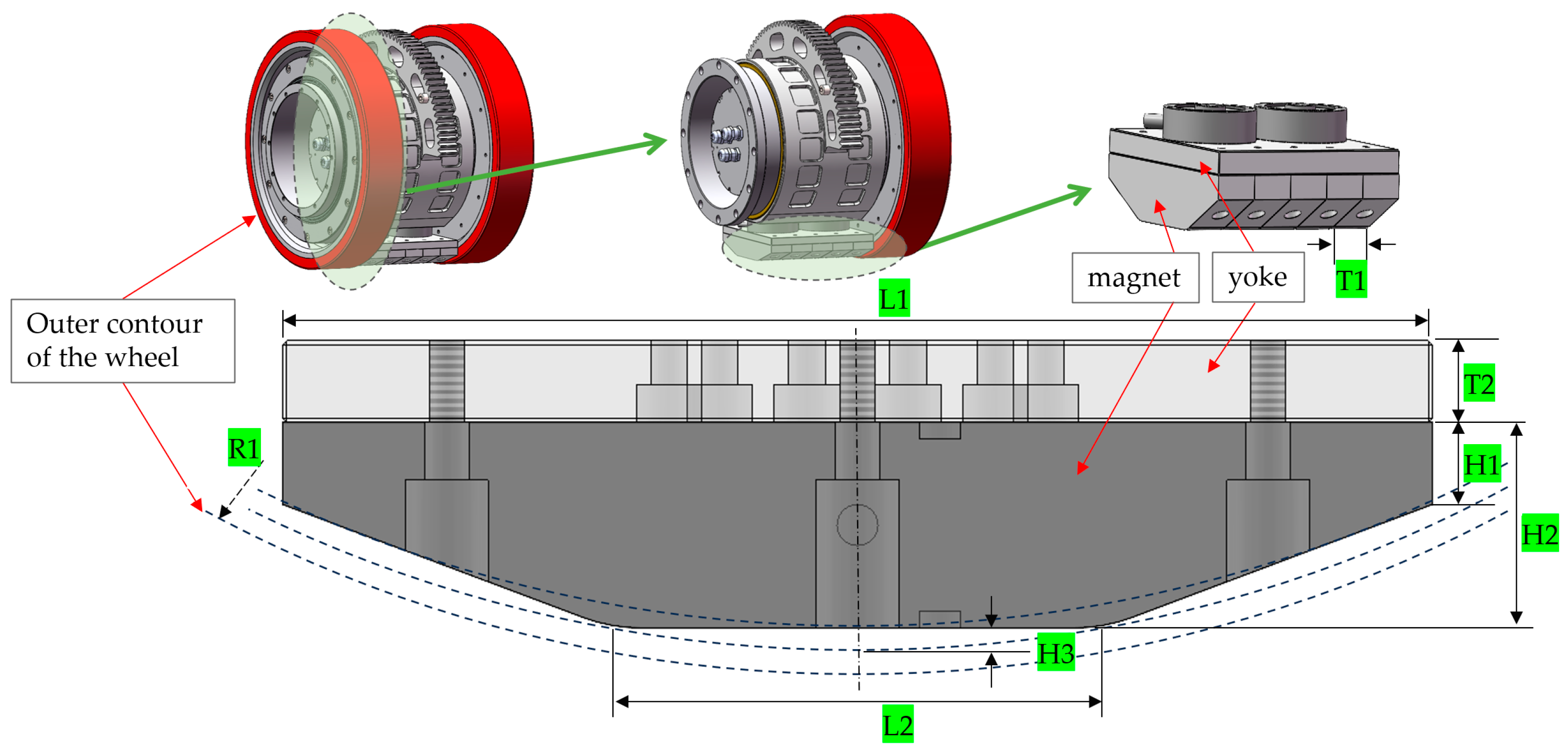
In order to achieve an optimal balance between magnetic adhesion performance and the mechanical structure of the wheel system, a new type of swinging magnetic adhesion unit was designed. It is composed of a combination of yoke and magnets magnetized in a Halbach array, located at the center of the wheel foot, and can rotate coaxially with the wheel foot. The design structure and a cross-section of the magnetic adhesion unit are shown in Figure 3. Its structure is mainly restricted by the length of the yoke, the length of the upper and lower ends of the magnet, and the height of the magnet. Its size parameters are shown in Table 1.
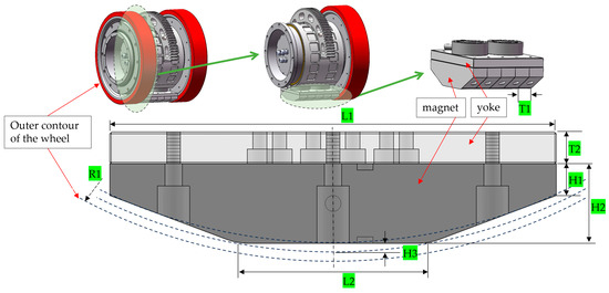
Figure 3.
Structure and cross-section of magnetic adhesion unit.

Table 1.
Size parameters of magnetic adhesion unit.
2.2. Analysis of Influence of Magnet and Yoke Thickness on Magnetic Force
The designed magnetic adhesion unit adopts a Halbach array, and the magnetic field varies sinusoidally in space, with one side of the magnetic field being enhanced and the other side being canceled out. However, to further increase the magnetic field strength on the working side, a yoke is often added to the backside. The yoke can guide the magnetic field lines to concentrate in the working area, thereby enhancing the magnetic field strength. To achieve a reasonable structure and high magnetic energy performance, simulations were conducted in the Maxwell software (AnsysEM21.1) for magnetic adhesion units with different yoke thicknesses. The larger the magnetic energy product and magnetic energy density of a permanent magnet of the same volume, the stronger the generated magnetic field strength. NdFeB (neodymium iron boron) was selected as the permanent magnet material due to its high magnetic energy product, remanence, and coercivity. The performance parameters of NdFeB N35 are shown in Table 2.
Table 2.
Performance parameters of NdFeB N35.
To design a reasonable magnetic adhesion unit parameter structure, the Maxwell software (AnsysEM21.1) was used to simulate the magnetic adhesion force of the yoke thickness and analyze the influence of the magnetic adhesion force of the magnetic adhesion unit on the thickness of the yoke. The simulation steps were as follows:
- Establish a magnetic adhesion unit model and import it into the Maxwell software (AnsysEM21.1); then, magnetize the magnets in a sequence according to the Halbach array, and set their material properties to N35.
- Establish a wall made of Steel-1008, with a mesh density of 10 mm for the yoke and wall and 8 mm for the yoke.
- Solve for the force acting on the wall with a space of 120% of the total volume.
- The wall-climbing robot adopts a non-contact magnetic adhesion method, and the distance between the magnetic adhesion unit and the wall surface is generally 5 mm. Therefore, set the simulation distance to 5 mm, and record the magnetic force of the magnetic adhesion unit at different yoke thicknesses. When setting up the optimization scheme, we formalized certain practical constraints. For example, we assumed a 5 mm air gap between the magnetic poles and the climbing surface. This 5 mm gap was not arbitrarily chosen; it accounts for typical surface roughness, protective coating thickness, and assembly tolerances in real-world applications. Throughout the optimization process, we treated this 5 mm gap as a design constraint representing the minimum allowable clearance.
- Analyze the simulation results, draw a curve of the changes in the magnetic attraction force with the thickness of the yoke, and obtain the fitting formula.
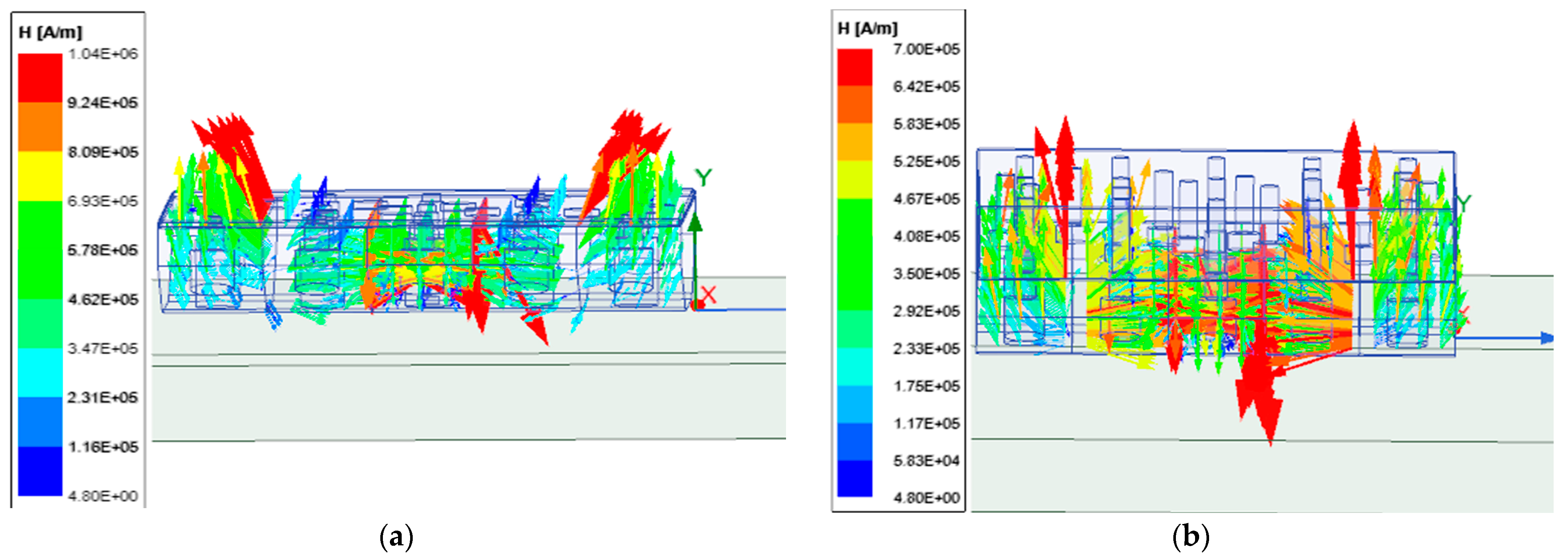
Although the Halbach array has a weak magnetic field on its backside, there may still be magnetic leakage. Adding a yoke can effectively shield the magnetic field on the back. This helps to evenly distribute the magnetic field, reduce non-uniformity and edge effects in the magnetic field, and minimize interference with surrounding equipment or materials.
Distribution cloud maps of the magnetic field strength for yokes with thicknesses of 2 mm and 20 mm are shown in Figure 4. According to the simulation results, the magnetic attraction force varies with the thickness of the yoke, as shown in Table 3.
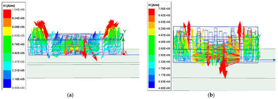
Figure 4.
Cloud map of magnetic field intensity distribution under two different yoke thicknesses: (a) 2 mm; (b) 20 mm.
Table 3.
Magnetic attraction at different yoke thicknesses.
From Table 3, we can see that the thickness of the yoke has almost no effect on the magnetic force on the enhanced side of the magnet, and after the thickness of the yoke reaches 10 mm, the magnetic attraction force barely increases with an increase in yoke thickness. However, an increase in the thickness of the yoke effectively improves the non-uniformity of the magnetic field.
2.3. Analysis of Influence of Magnet Height on Magnetic Force
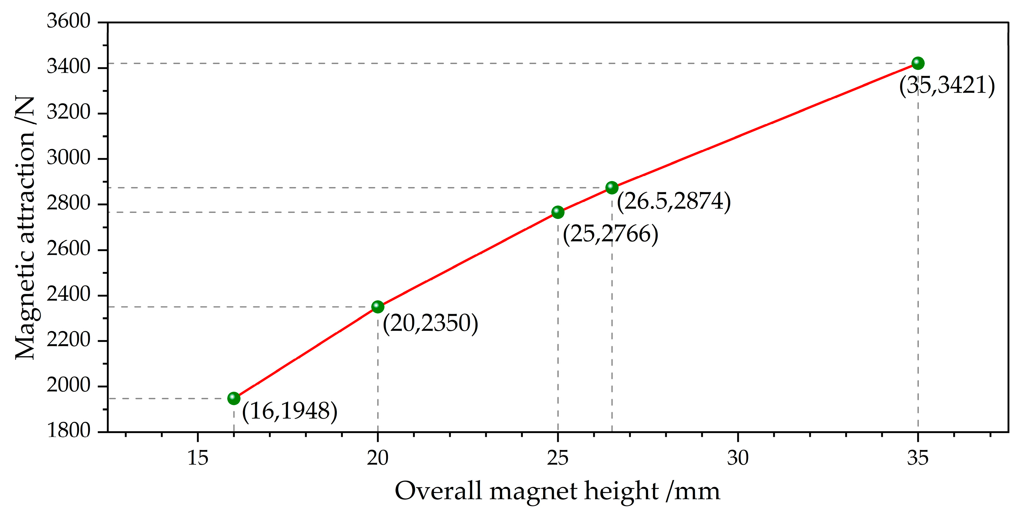
Compared to the yoke thickness, the magnet height has a more significant impact on the magnetic force. The basic overall height of the magnet is 15 mm. On this basis, the magnet’s overall height was continuously increased for the simulation to obtain the magnitude of the magnetic adhesion unit’s magnetic force at different magnet heights. The simulation results of this analysis are shown in Figure 5, which can be approximated as a linear variation.
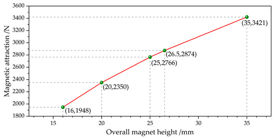
Figure 5.
Variation in magnetic attraction with magnet height.
To ensure the adhesion safety and stability of the wall-climbing robot during practical operation and to prevent it from falling during operation, the final design of the magnetic adhesion unit features a magnet height of 25 mm, achieving a single magnetic adhesion unit force of 2766 N under normal working conditions. Additionally, sufficient safety redundancy is incorporated to ensure adequate adhesion and safety under various wall and load conditions.
2.4. Influence of Distance and Angle Between Magnetic Adhesion Unit and Wall on Magnetic Attraction Force
The magnetic adhesion unit is a key component in the stable adsorption of wall-climbing robots to wall surfaces, and its adsorption performance directly impacts the robot’s mobility and stability on vertical, inclined, and curved walls. The magnitude of magnetic attraction is not only determined by the structure and material properties of the magnetic adhesion unit but also significantly influenced by the distance and relative angle between the magnetic adhesion unit and the wall. By exploring the variations in distance and angle between the magnetic adhesion unit and the wall, this study investigates the impact of these factors on the magnetic force under typical operating conditions, such as forward movement on a vertical wall and transitions between wall surfaces, providing an important basis for the design and control of magnetic adhesion units under different working conditions.
The distance between the magnetic adhesion unit and the wall is an important factor affecting the magnetic attraction force. As the distance between the magnetic adhesion unit and the wall increases, the strength of the magnetic field will significantly weaken, resulting in a sharp decrease in magnetic attraction. Therefore, to ensure that the robot maintains stable attachment on the vertical plane, the distance between the magnetic adhesion unit and the wall should be kept as close as possible to the minimum value required by the design. When advancing vertically, the magnetic attraction must be strong enough to overcome the influence of gravity and other external forces on the robot, ensuring that it can firmly adhere to the wall without falling off. Through simulation, the minimum magnetic attraction required to ensure the stability of wall-climbing robots on different wall materials and surface states can be determined.
The magnetic adhesion force between the magnetic adhesion unit and the wall at different distances was measured in the simulation software Maxwell (AnsysEM21.1). A vector distribution diagram of the magnetic flux density of the magnetic adhesion unit in space is shown in Figure 6. The results were fitted with data to obtain the relationship between the magnetic adhesion force and the distance between the magnetic adhesion unit and the wall, as shown in Figure 7.
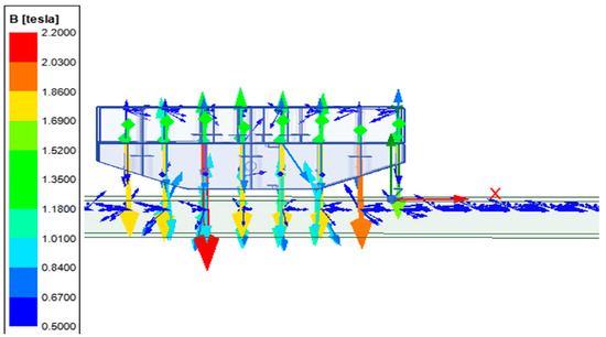
Figure 6.
Magnetic induction vector distribution map.
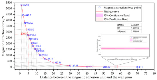
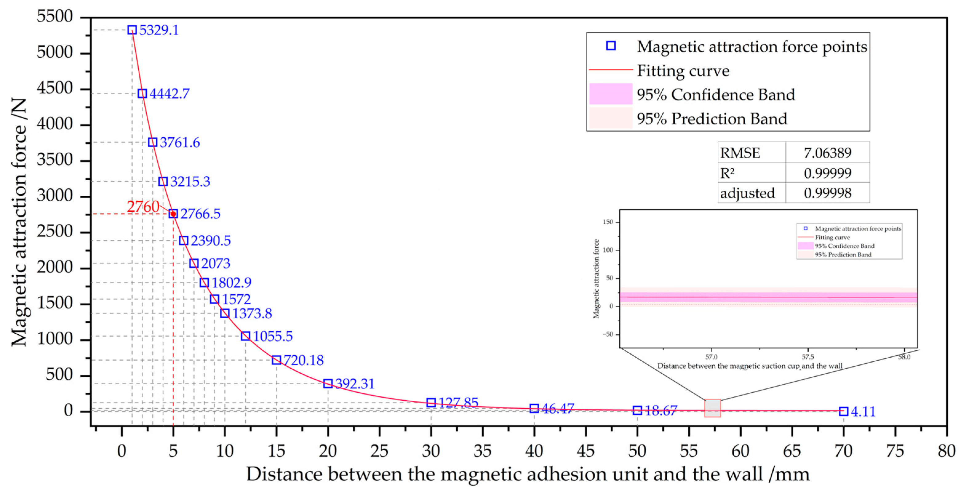
Figure 7.
Relationship between magnetic attraction force and air gap distance.
The fitting relationship function between the magnetic attraction force F and the air gap distance d is given by:
The fitting results were obtained in MATLAB (R2021b) using an exponential regression model and the Trust-Region algorithm. Both the R2 and adjusted R2 were 0.9999, the root-mean-square error (RMSE) was 7.06389, and the range of magnetic force variation was in the order of 103, indicating that the error was very small, with a 95% confidence boundary. Under normal working conditions, there is a distance of 5 mm between the magnetic adhesion unit of the wall-climbing robot and the wall surface, with a fitted magnetic adhesion force of 2760 N and a simulated magnetic adhesion force of 2766 N. The error was only 0.25%, indicating that the fitting is highly effective.
During the wall transition, the magnetic adhesion unit of the front wheel rotates by a certain angle, reducing the magnetic adhesion force to facilitate the smooth lifting of this wheel. As the front wheel approaches the vertical wall near the corner, the magnetic adhesion force stabilizes it and attracts it to the wall. During the transition phase, the magnetic adhesion unit undergoes two rotational processes. In order to ensure that the robot does not experience unstable operation—such as slippage, loss of contact, or unbalanced posture—caused by insufficient adhesion force during wall transitions or inclined movements, the magnetic attraction force must be dynamically adjusted to cope with the decrease in magnetic adhesion force caused by angle changes. Through simulation, the influence of different inclination angles on magnetic attraction can be studied to obtain the minimum value of magnetic attraction required during a wall transition and to help design control strategies to adjust the angle of the magnetic adhesion unit and ensure sufficient adhesion during transitions.
To match the actual working conditions, during forward movement of the wall-climbing robot on a flat surface, the distance between the magnetic adhesion unit and the wall was maintained at 5 mm, with a wheel diameter of 320 mm. Therefore, the simulated rotation center was 160 mm away from the plane, and the distance between the magnetic adhesion unit and the plane was also the same as in reality. The simulation results of the magnetic adhesion force variation with the angle of the magnetic adhesion unit are shown in Table 4.
Table 4.
Relationship between magnetic attraction and rotation angle of magnetic adhesion unit.
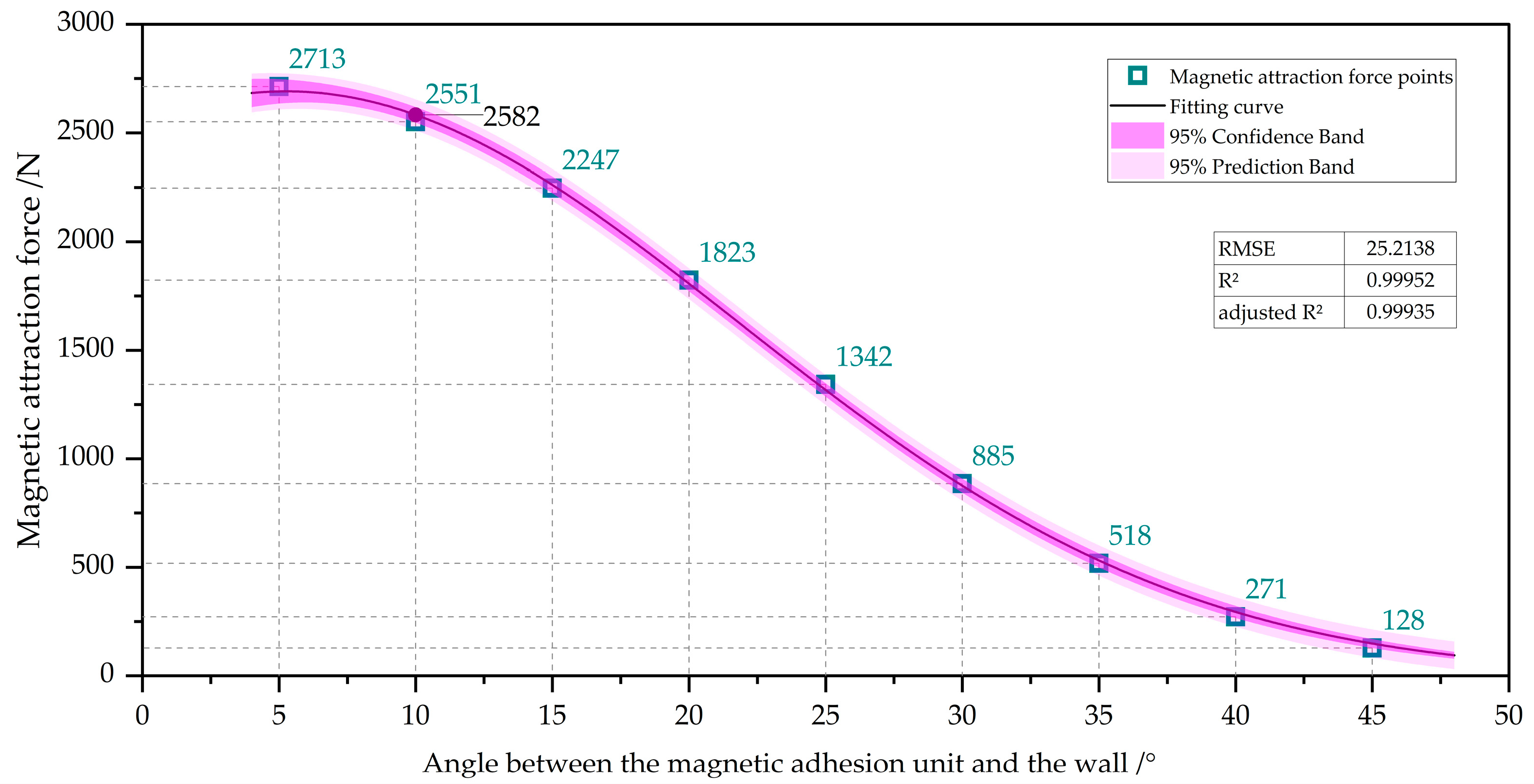
As indicated in Table 4, the magnetic force changes most sharply between 10° and 30°. Using a two-dimensional plane to establish an x-y coordinate system, the wall-climbing robot undergoes a symmetrical process of force in the x and y directions during the internal bending angle transition. After rotating 50°, the magnetic force tends to be negligible. Therefore, the simulation results of the magnetic force from 0° to 45° were fitted to obtain the following curve fitting graph, as shown in Figure 8.
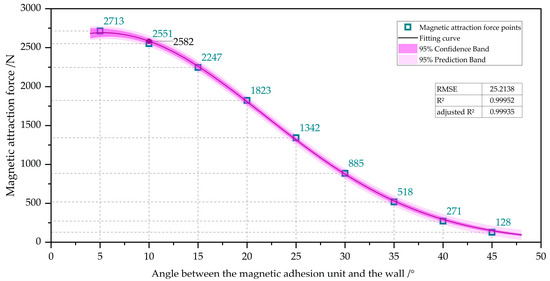
Figure 8.
Relationship between magnetic attraction and the angle of the magnetic adhesion unit relative to the wall surface.
The fitting formula for the exponential decay between magnetic attraction force F and angle θ is as follows:
The research presented in this section will provide a theoretical foundation and design guidance for the application of wall-climbing robots in complex environments, particularly in the case of transition surfaces and inclined walls, ensuring that robots can maintain stable adhesion and smooth movement. By combining simulations and experimentation, we will further verify the correctness and applicability of these conclusions, ultimately achieving system optimization and improving the adsorption performance of wall-climbing robots.
Based on the above analysis, this chapter will determine the minimum adhesion force required for magnetic adhesion units under different operating conditions and the optimal design parameters. All of these results will provide data support for the design of control systems for wall-climbing robots, ensuring their stable operation in complex wall environments.
2.5. Analysis of Influence of Magnetic Attraction Units on Stress Distribution of Iron Plates
Unlike the simulation environment, the strong magnetic force generated by the magnetic attraction unit in the experimental environment not only provided adsorption to the steel plate but also caused bending deformation, resulting in changes in the distance between different parts of its surface. Therefore, a Q235 steel plate with dimensions of 400 mm × 400 mm × 11 mm was selected as the simulation object. In the Maxwell software (AnsysEM21.1) simulation environment, the steel plate was divided into 25 equivalent regions to analyze the magnetic force distribution, and the magnetic force concentration in different regions was obtained through vector analysis. We applied equal force to the same object on the workbench while configuring the properties of the Q235 steel plate as follows: density of 7860 kg/m3, Young’s modulus of 208 MPa, Poisson’s ratio of 0.277, and yield strength of 235 MPa. The constraints were set according to the experimental conditions, with the steel plate and the aluminum alloy plate behind it as binding constraints and the holes in the aluminum alloy as fixed constraints. The simulation results show that the area directly below the magnetic attraction unit had the largest deformation due to the concentration of magnetic force, which reached 0.0347 mm. The overall deformation is shown in Figure 9.
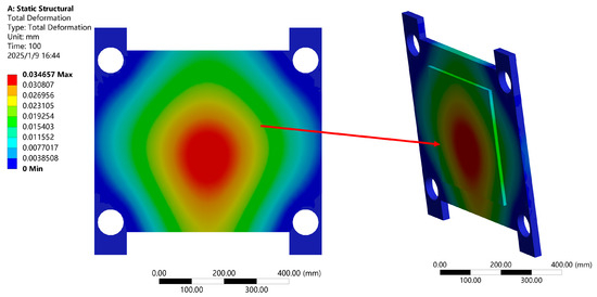
Figure 9.
Overall structural deformation cloud map.
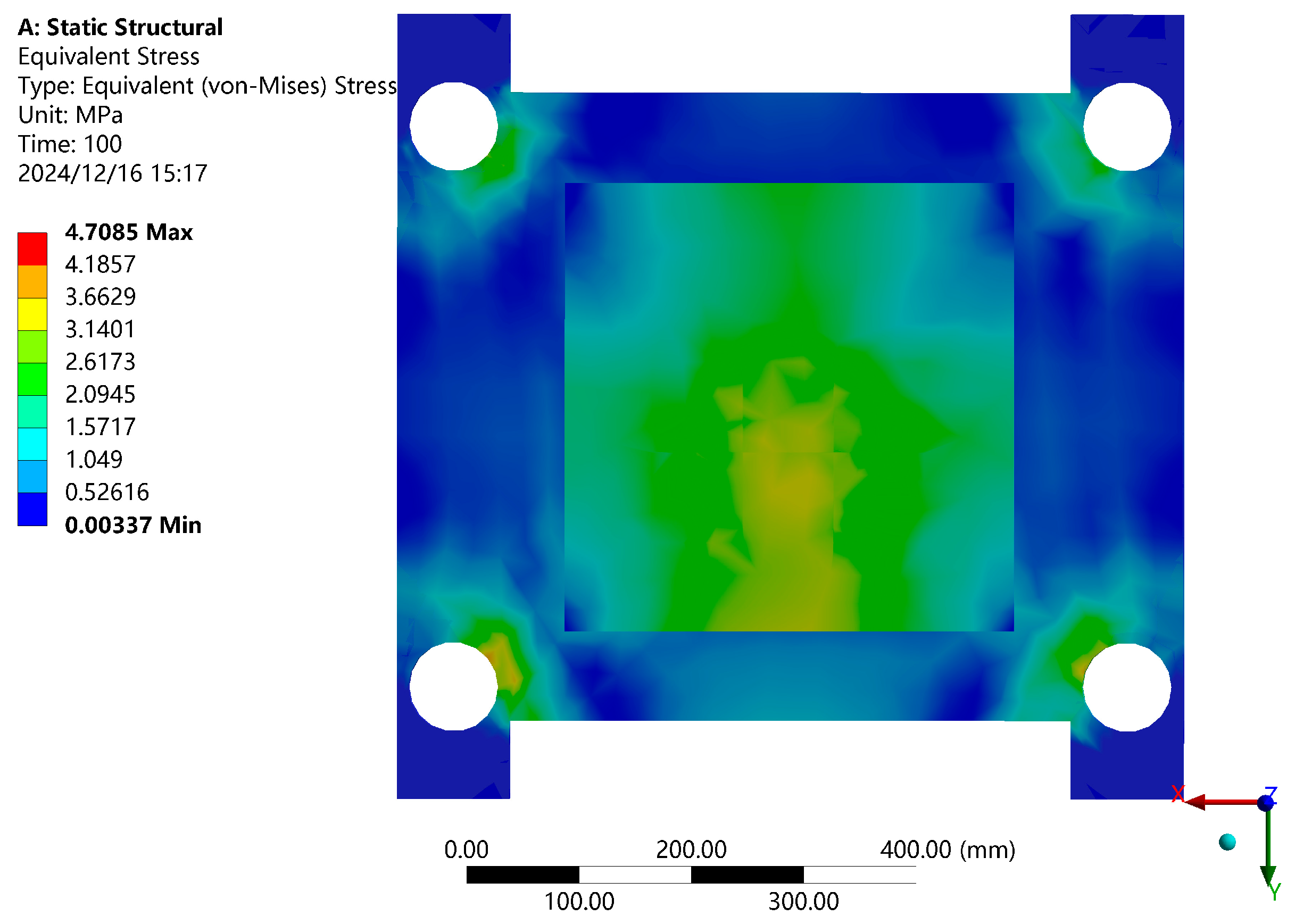
The deformation was significantly reduced in the area close to the fixed support. The stress was distributed in the magnetic concentration and support areas, reaching about 3.5 MPa. A stress distribution diagram is shown in Figure 10.

Figure 10.
Stress distribution cloud map.
Due to the fact that the magnetic attraction unit is not placed at the center of the board, as shown in Figure 10, the deformation and stress distribution were not symmetrically distributed vertically. Therefore, in addition to the deformation in the central area, the different forces acting on the top and bottom can also cause the support board to tilt to a certain extent. This influencing factor will be considered in subsequent experiments.
3. Design of Robot’s Magnetic Wheels
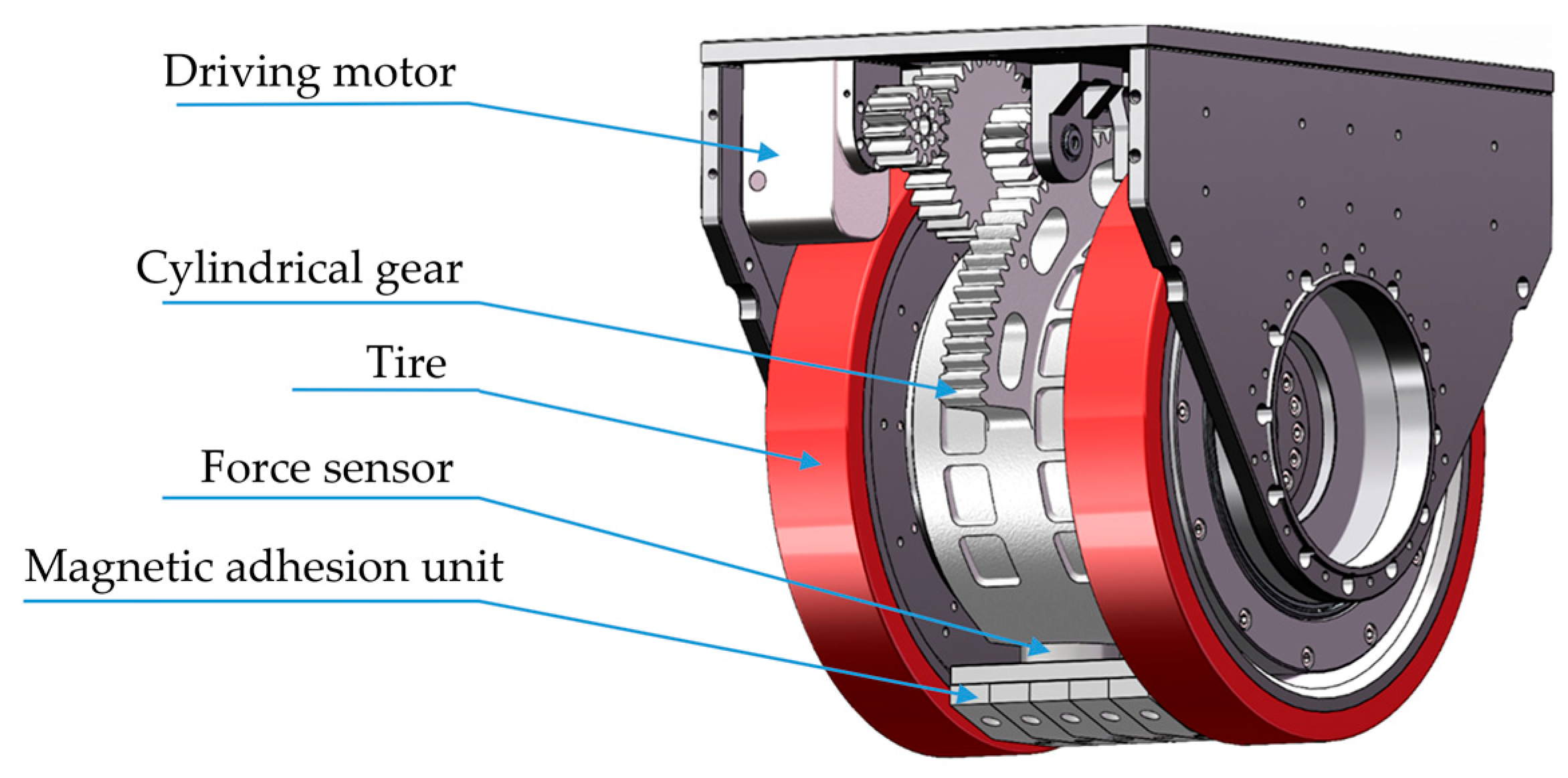
As specialized robots capable of performing tasks in complex wall environments, the performance and stability of wall-climbing robots rely heavily on the design of their attachment mechanisms. The wall-climbing function of these robots mainly relies on magnetic adhesion wheels, which are composed of magnetic adhesion units, force sensors, cylindrical gear pairs, driving motors, and wheels, as shown in Figure 11. By generating sufficient adhesion force, the robot can firmly adhere to the wall and adapt to complex working conditions such as different inclination angles and wall transitions.

Figure 11.
Structural diagram of magnetic adhesion wheel foot.
The dimensional parameters of the magnetic adhesion unit were introduced in Section 2.1. The rotation of the magnetic adhesion unit is driven by a motor, which is connected to a cylindrical gear and transmitted through a gear pair to rotate the magnetic adhesion unit by a specific angle. The motor drives the operation of the cylindrical-gear transmission system. When the force sensor detects that the magnetic adhesion force between the magnetic adhesion unit and the wall has reached the preset value, the motor stops working, thereby enabling intelligent adjustment of the magnetic force. In this way, the system can adaptively adjust the position of the magnetic adhesion unit during the wall-climbing process, ensuring stable attachment and efficient movement of the robot on vertical walls. In previous studies, Maxwell (AnsysEM21.1) simulation was used to analyze the magnetic attraction between the magnetic adhesion unit and the wall at different angles, providing a basis for establishing the parameter settings of control systems.
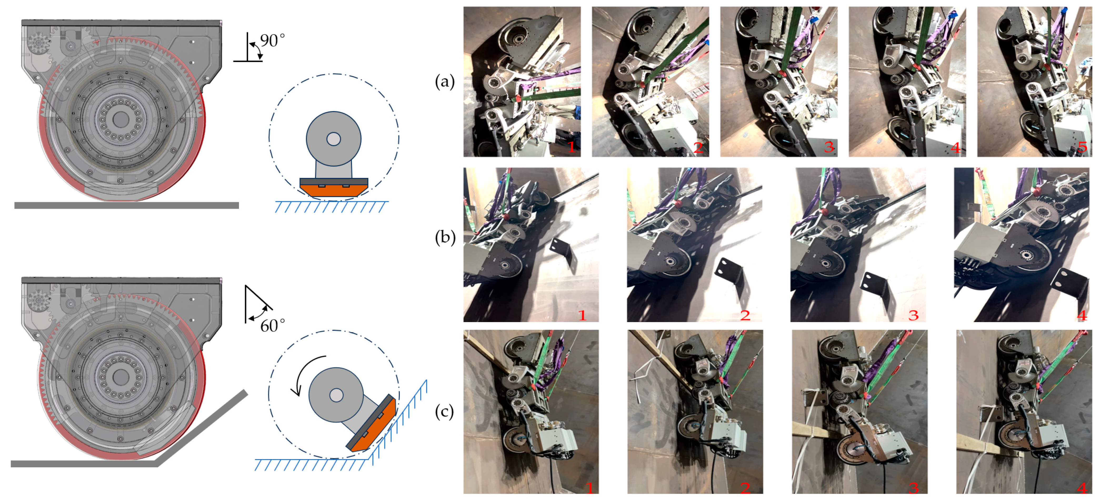
When the magnetic adhesion unit is adsorbed parallel to the wall surface, the magnetic attraction force is at maximum. When the angle formed with the wall surface is greater than 60 degrees, the magnetic attraction force tends to be zero. Therefore, rotating the magnetic adhesion unit can lead to adsorption and demagnetization of the wheel. This effect is shown in Figure 12, where Figure 12a shows the process of the wall-climbing robot climbing from a horizontal plane to a vertical plane; Figure 12b shows the robot driving on a curved wall; and Figure 12c shows the process of the robot crossing an obstacle.

Figure 12.
Diagrams of the adsorption and demagnetization states of a wheel under different magnetic adhesion unit angles, and images of the practical application of the robot in the experiments, (a) Wall transition; (b) Curved driving; (c) Obstacle crossing.
4. Magnetic Force Experiment
An experiment was conducted to verify the influence of the magnetic adhesion unit’s design parameters on the magnetic force. The purpose of this experiment was to evaluate the actual effect of the distance and angle between the adhesion unit and the wall on magnetic attraction. The equipment used in the experiment included a magnetic attraction detection platform, a magnetic adsorption unit, and a rotating magnetic adsorption unit. The experimental steps and parameters were as follows.
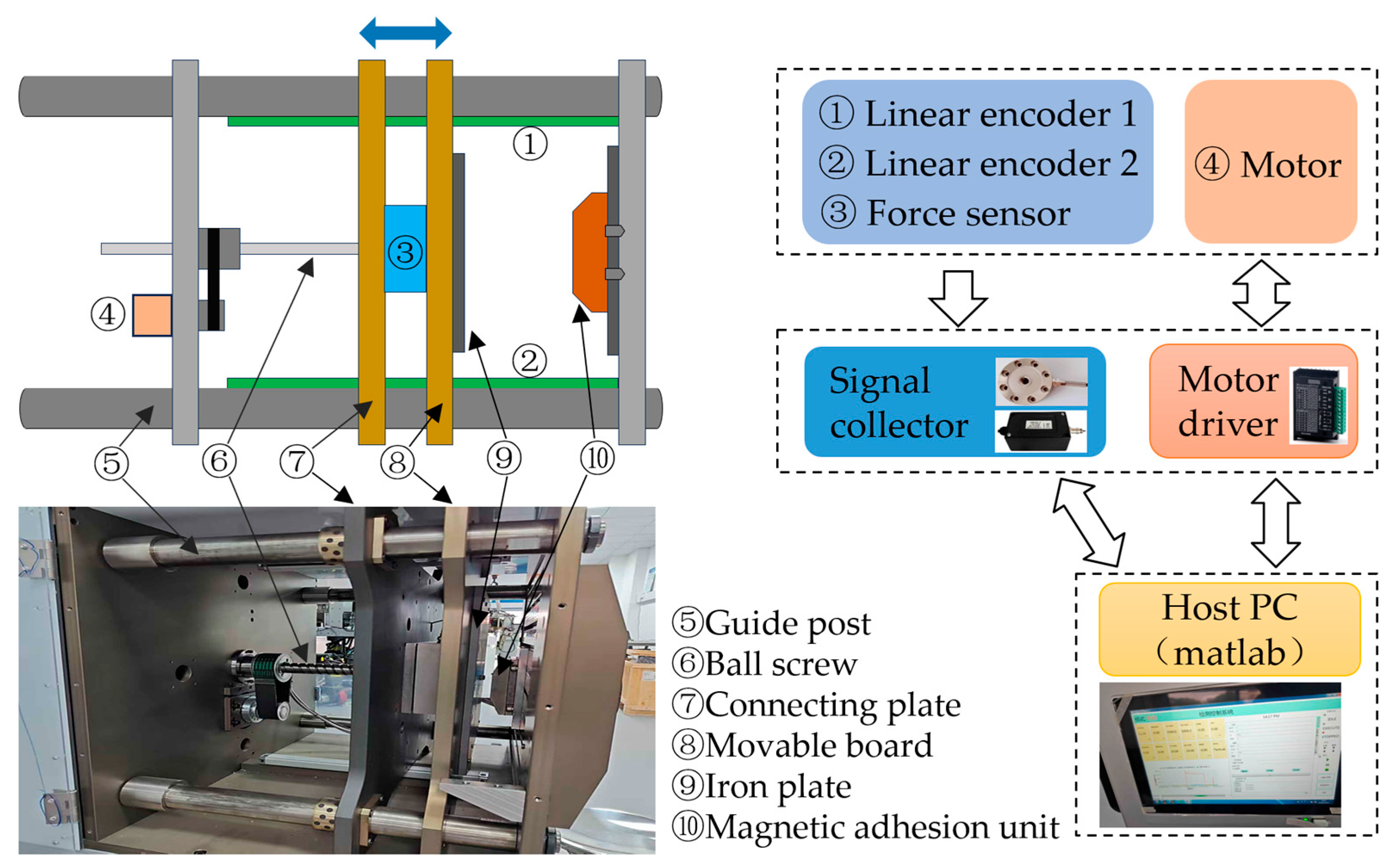
The experimental system for testing the adsorption force between the magnetic adhesion unit and wall surface is shown in Figure 13. The system mainly consisted of guide posts, a connecting plate, a movable board, an iron plate, and a ball screw. The connecting plate and movable plate were installed and constrained on four guide posts, with the force sensor (656C-500 Kg) installed between them. The iron plate was assembled on the movable board. A motor (KGM-20CLKES, KAIXUAN, Suzhou, China) drove the ball screw to move the movable and connecting plates left and right on the guide posts. Two linear encoders (KA300-320, SINO, Guangzhou, China) were installed on the top and bottom of the guide posts, respectively. During the experiment, the magnetic adhesion unit was fixed on the load plate at the end of the platform, and the force sensor and movable board were placed in their original positions. The movable board moved forward along the guide posts until it reached the predetermined end point, reducing the distance between the magnetic adhesion unit and the iron plate, with the end position 2 mm away from the magnetic adhesion unit. The forward speed of the movable board was 0.1 mm/s.
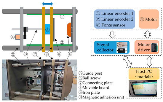
Figure 13.
The experimental system of the adsorption force test between the magnetic adhesion unit and the wall surface.
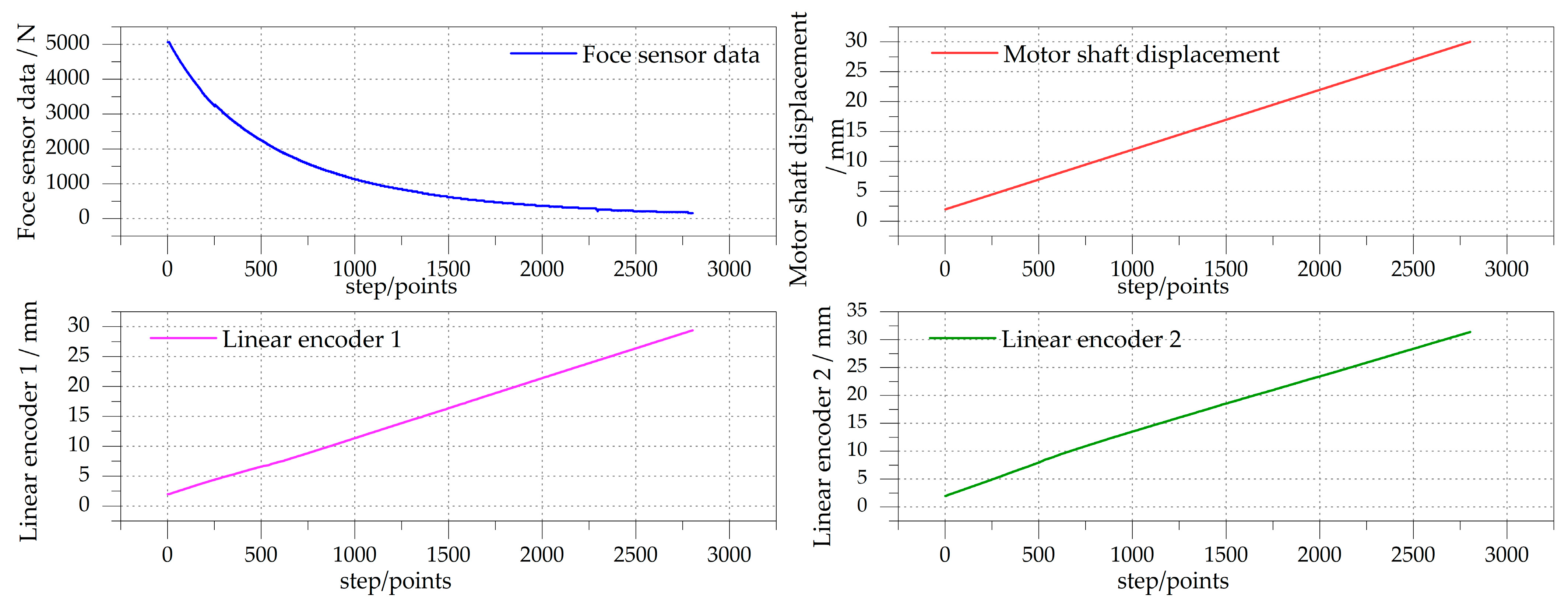
The system synchronously collected data from two linear encoder sensors, the force sensor, and the motor shaft displacement output. As shown in Figure 14, 2804 data points were collected during one measurement process, with a timestamp range of [14:35:41.082, 15:22:24.000]. This simulation showed that the magnetic force was concentrated in the area directly below the magnetic attraction unit, and the upper and lower areas were subjected to unequal forces, resulting in different offset distances. So, there was a little deviation between the data of linear encoders 1 and 2 in Figure 14. Using the mean method, the data were processed to obtain the actual distance between the magnetic adhesion unit and the iron plate.
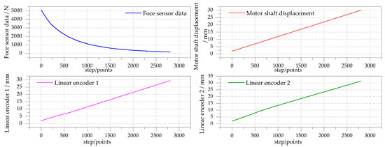
Figure 14.
Four sets of data collected during one measurement process.
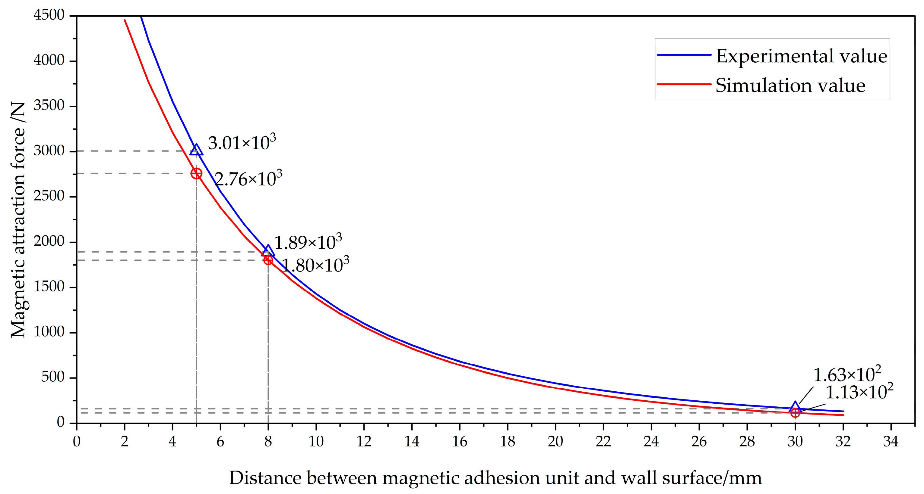
The magnetic force variation with a gap of 2–35 mm was measured, and the relationship between the magnetic adhesion force and spacing variation was derived during the experimental process. The data were fitted, and as the magnetic adhesion force was much lower than the robot’s own gravity after a distance exceeding 32 mm, it had almost no effect. Therefore, the data after 32 mm were not included in the figure. A comparison of the simulated and experimental correlations between the magnetic adhesion force and the distance between the magnetic adhesion unit and the wall is shown in Figure 15.
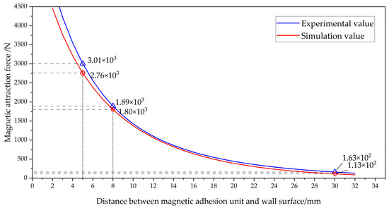
Figure 15.
Comparison of simulated and experimental correlations between magnetic adhesion force and distance between magnetic adhesion unit and wall surface.
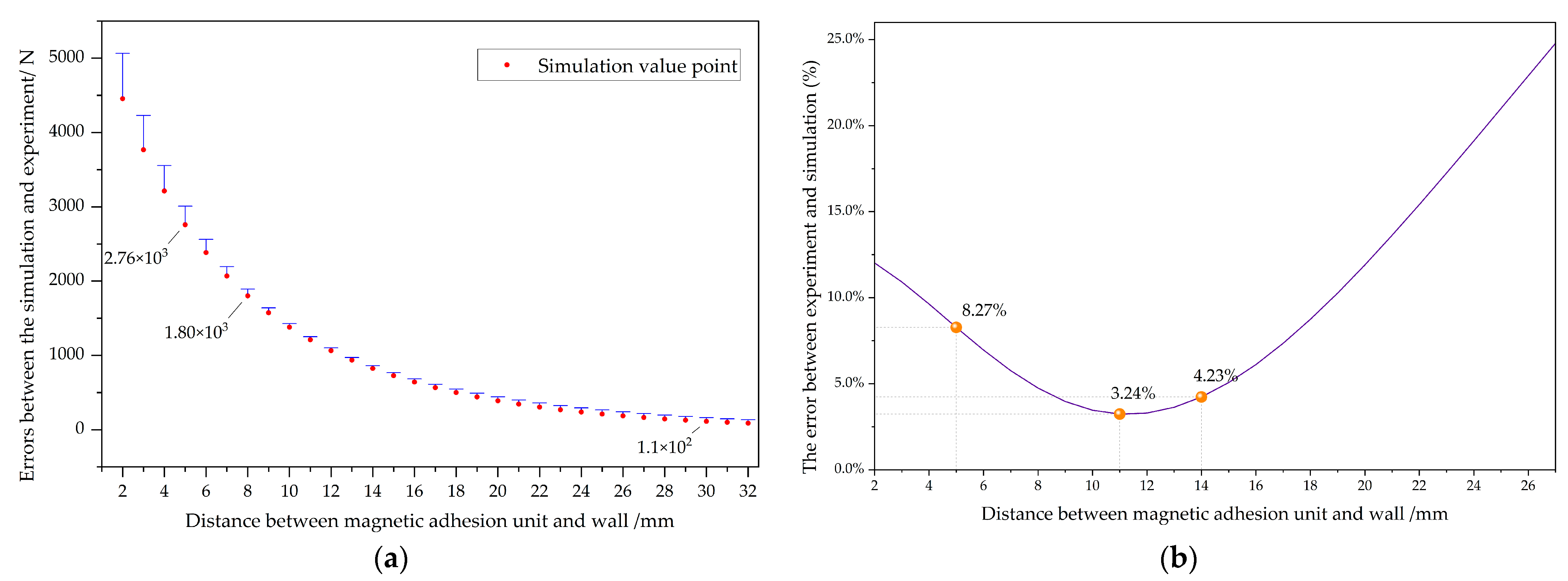
The experimental value curve in Figure 15 represents the experimentally measured magnetic attraction values, which were slightly higher than the simulated values. When the wall-climbing robot works on a flat surface, the distance between the magnetic adhesion unit and the wall surface is 5 mm. The experimentally measured magnetic adhesion force was 3010 N, and the simulation result was 2760 N, with an error of 8.27%. An error diagram of the experiment and simulation is shown in Figure 16. When the distance reached 11 mm, the error was the smallest, at only 3.24%. After that, the error gradually increased but did not exceed 25%.
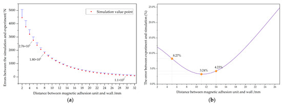
Figure 16.
The errors between the simulation and experiment when the magnetic adhesion unit was at different distances from the wall. (a) Error bar; (b) Error ratio.
Similarly, in MATLAB (R2021b), using an exponential regression model and the Trust-Region algorithm, the fitting formula for calculating the experimentally measured relationship between the air gap distance and magnetic adhesion force was as follows:
During the experiment, the iron wall gradually moved away from the magnetic adhesion unit, and the wall was constantly subjected to the magnetic adhesion force of the magnetic adhesion unit, resulting in slight deformation of the wall. The maximum deformation simulated was 0.0347 mm, and the actual distance decreased due to the deformation. The impact on the change in magnetic adhesion force can be ignored, so the resulting error is within an acceptable range.
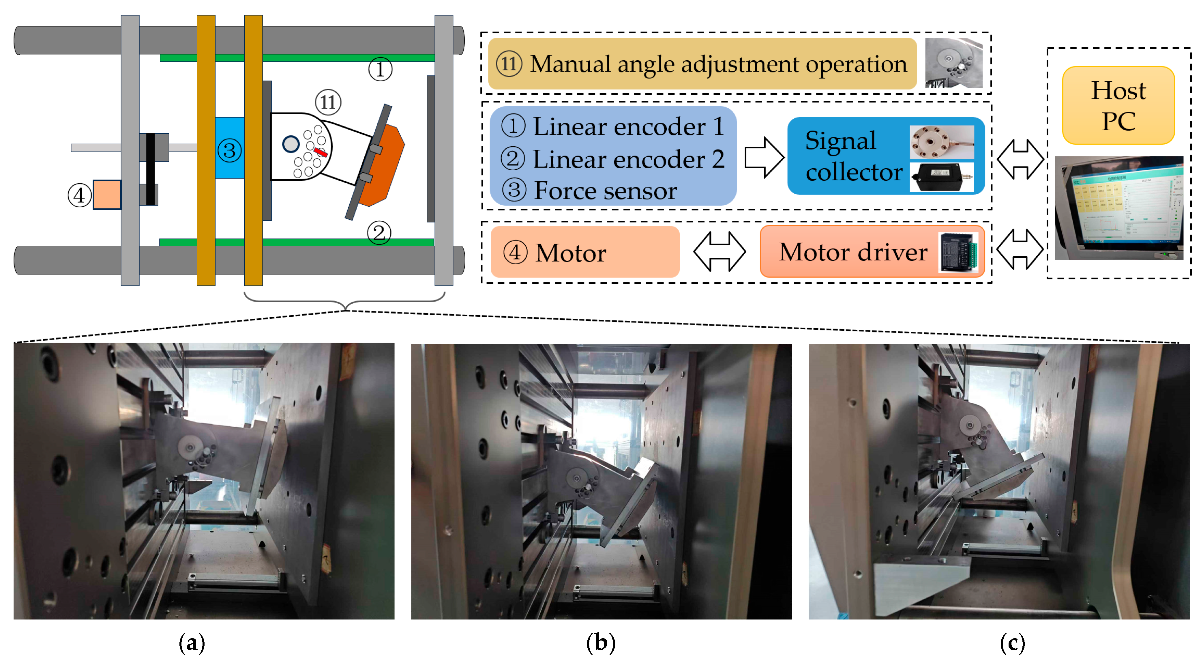
The experimental system for testing the adsorption force at different magnetic adhesion unit angles is shown in Figure 17. Based on the experimental platform shown in Figure 13, the supporting mechanism was located on the movable board. The magnetic adhesion unit could rotate around the central axis of the supporting mechanism, on the surface of which there were evenly spaced 10-degree pin holes. The angle adjustment between the magnetic adhesion unit and the wall surface was performed manually, with the rotation center axis of the supporting mechanism functioning as the wheel center of the wall-climbing robot. We set the distance from the outer surface of the magnetic adhesion unit to the center (the rotation radius) to 155 mm and measured the magnetic force changes during the rotation of the magnetic adhesion unit in sequence, sampling at intervals of 10 and recording the magnetic force changes. Figure 17a–c show the test states when the magnetic adhesion unit angles were 10, 30, and 60, respectively. Comparison curves between the simulation and experiment are shown in Figure 18.
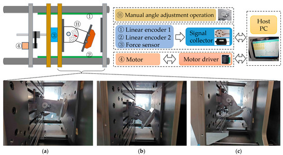
Figure 17.
Experimental diagram of different magnetic adhesion unit angles: (a) 10 degrees; (b) 30 degrees; (c) 60 degrees.

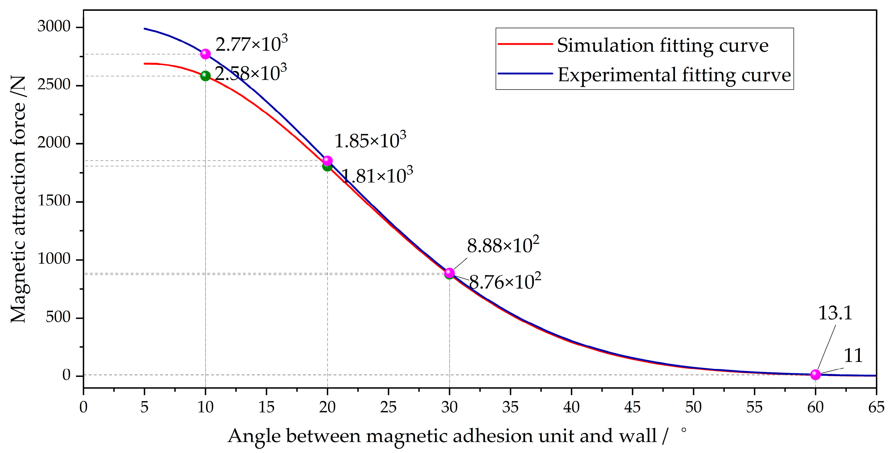
Figure 18.
Comparison curve between simulation and experiment at different angles.
In MATLAB (R2021b), a Gaussian regression model and the Trust-Region algorithm were used to obtain the following fitting curve for the relationship between the magnetic adhesion unit’s angle in relation to the wall surface and the magnetic force during the experiment:
When the rotation angle of the magnetic adhesion unit exceeded 60 degrees, the magnetic force exerted on the wall dropped to approximately 10 N, which is negligible. As shown in Figure 18, a comparison of the simulation and experimental results, the magnetic force demonstrated good agreement within the range of 2060. An error diagram of the simulation and experimental results is shown in Figure 19.
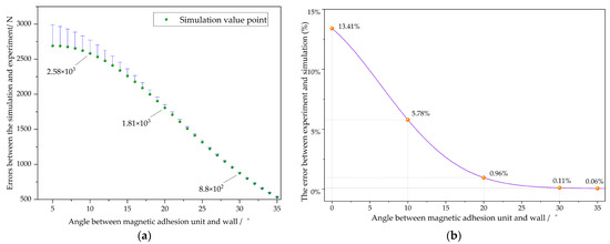
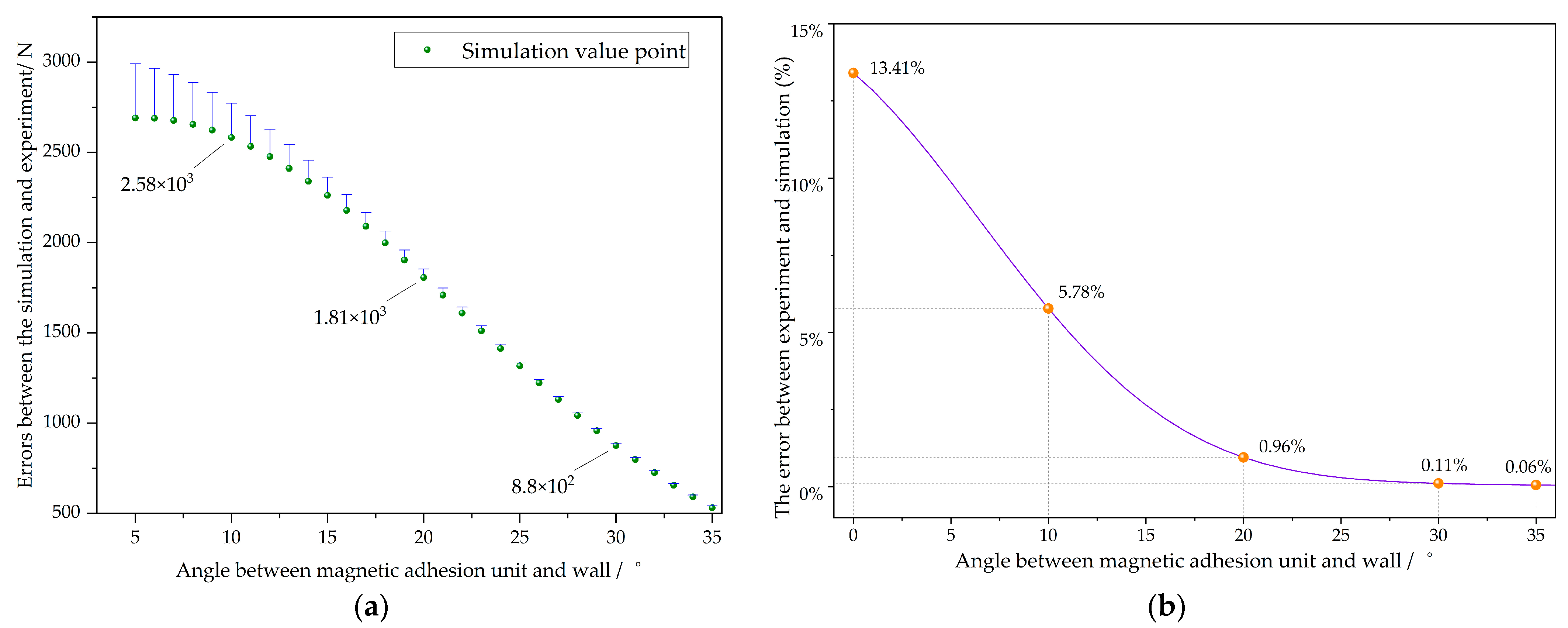
Figure 19.
The error between simulation and experimental results when the magnetic adhesion unit is at different angles from the wall. (a) Error bar; (b) Error ratio.
When the magnetic chuck was 10° from the wall, the error between the simulation and the experiment was 5.78%. The error diminished progressively with the escalation in the rotation angle. When the angle exceeded 35°, the error approached 0. The overall attenuation was exponential. When the rotation angle reached 25°, the magnetic attraction decayed to half of the original value.
5. Conclusions
In this paper, a new swinging magnetic adhesion unit was designed to optimize the balance of design parameters such as the adsorption force and wheeled movement. Then, the air gap distance and the angle between the magnetic adhesion unit and the wall were simulated in the Maxwell software (AnsysEM21.1). Finally, experiments were conducted to verify the effects of the gap and angle on the magnetic adsorption force. The experimental verification results show that the designed magnetic adhesion unit has high adhesion performance under different wall conditions, and the error between the simulation and experimental results is controlled within a small range. They also show that the magnetic adhesion unit can maintain excellent adhesion at different wall angles and under varying load conditions, providing strong technical support for the creation of stable high-load-bearing wall-climbing robots. The maximum adsorption force of the optimized magnetic adhesion unit reached 2767 N, which is about 10% higher than that of the traditional design, and the error between the simulation and experimental results was only 8.3%.
In addition, based on the optimized magnetic adhesion unit design, the flexibility and adaptability of existing wall-climbing robots in complex wall environments can be further improved by introducing a five-wheel structure and a multi-degree-of-freedom motion design. The five-wheel wall-climbing robot will be able to achieve a high load capacity while ensuring more efficient wall transitions and enhanced adaptability on various terrains. Future research will combine deep learning and artificial intelligence to optimize the motion control of the five-wheel system, improve the robot’s dynamic response capability and stability in complex environments through intelligent algorithms, and further enhance its adaptability and intelligence level. With the combination of these technologies, in the future, five-wheel wall-climbing robots will be more widely used in fields such as aerial operations, industrial equipment inspection, and building maintenance.
Author Contributions
Conceptualization, H.Z., P.L. and H.J.; methodology, H.Z.; software, H.Z. and H.J.; validation, P.L., L.L. and H.Z.; formal analysis, P.L.; writing—original draft preparation, H.Z. and P.L.; writing—review and editing, H.Z. and H.J.; supervision, H.Z.; project administration, L.L. All authors have read and agreed to the published version of the manuscript.
Funding
This research was funded by the National Natural Science Foundation of China, NO.52475063 and the Jiaxing Public Welfare Research Project of Zhejiang Province of China, NO.2024AD10036.
Data Availability Statement
The data that support the findings of this study are available on request from the corresponding author.
Conflicts of Interest
The authors declare no conflicts of interest.
References
- Liu, Y.W.; Yu, Y.; Wang, D.Q.; Yang, S.; Liu, J.G. Mechatronics design of self-adaptive under-actuated climbing robot for pole climbing and ground moving. Robotica 2022, 40, 2255–2274. [Google Scholar] [CrossRef]
- Nguyen, S.T.; La, H.M. A climbing robot for steel bridge inspection. J. Intell. Robot. Syst. 2021, 102, 75. [Google Scholar] [CrossRef]
- Liu, J.H.; Padrigalan, K.E. The kinematic analysis of a wind turbine climbing robot mechanism. Appl. Sci. 2022, 12, 1210. [Google Scholar] [CrossRef]
- Wang, Z.; Zhang, K.; Chen, Y.; Luo, Z.; Zheng, J. A real-time weld line detection for derusting wall-climbing robot using dual cameras. J. Manuf. Process. 2017, 27, 76–86. [Google Scholar] [CrossRef]
- Nansai, S.; Mohan, R.E. A survey of wall-climbing robots: Recent advances and challenges. Robotics 2016, 5, 14. [Google Scholar] [CrossRef]
- Gao, F.M.; Fan, J.C.; Zhang, L.B.; Jiang, J.K.; He, S.J. Magnetic Crawler Climbing Detection Robot Basing on Metal Magnetic Memory Testing Technology. Robot. Auton. Syst. 2020, 125, 103439. [Google Scholar] [CrossRef]
- Tian, T.L. Research on Wall-Climbing Robot Technology and System for Oil Tank Inspection; Tsinghua University: Beijing, China, 2004. [Google Scholar]
- Brusell, A.; Andrikopoulos, G.; Nikolakopoulos, G. A survey on pneumatic wall-climbing robots for inspection. In Proceedings of the 2016 24th Mediterranean Conference on Control and Automation (MED), Athens, Greece, 21–24 June 2016; pp. 220–225. [Google Scholar]
- Liu, Y.; Sun, S.; Wu, X.; Mei, T. A wheeled wall-climbing robot with bio-inspired spine mechanisms. J. Bionic Eng. 2015, 12, 17–28. [Google Scholar] [CrossRef]
- Wang, L.; Zhou, Q.; Xu, S. Role of locust Locusta migratoria manilensis claws and pads in attaching to substrates. Chin. Sci. Bull. 2011, 56, 789–795. [Google Scholar] [CrossRef]
- Autumn, K.; Sitti, M.; Liang, Y.A.; Peattie, A.M.; Hansen, W.R.; Sponberg, S.; Full, R.J. Evidence for van der Waals adhesion in gecko setae. Proc. Natl. Acad. Sci. USA 2002, 99, 12252–12256. [Google Scholar] [CrossRef] [PubMed]
- Cui, D. Dynamic Analysis and Navigation Control of Tracked Wall-Climbing Robot; Jilin University: Changchun, China, 2021. [Google Scholar]
- Hu, J.; Han, X.; Tao, Y.; Feng, S. A magnetic crawler wall-climbing robot with capacity of high payload on the convex surface. Robot. Auton. Syst. 2022, 148, 103907. [Google Scholar] [CrossRef]
- Vlasova, N.S.; Bykov, N.V. The Problem of Adhesion Methods and Locomotion Mechanism Development for Wall-Climbing Robots. arXiv 2019, arXiv:1905.09214. [Google Scholar]
- Mizota, Y.; Goto, Y.; Nakamura, T. Development of a wall-climbing robot using the mobile mechanism of continuous traveling waves propagation. In Proceedings of the IEEE International Conference on Robotics & Biomimetics (IEEE ROBIO 2018), Kuala Lumpur, Malaysia, 12–15 December 2018. [Google Scholar]
- Dong, S. Gravity and inertial load adaptive control of wall-climbing robot. J. Eng. 2019, 13, 442–446. [Google Scholar] [CrossRef]
- Iborra, A.; Pastor, J.A.; Alonso, D.; Alvarez, B.; Ortiz, F.J.; Navarro, P.J.; Fernández, C.; Suardiaz, J. A cost-effective robotic solution for the cleaning of ships’ hulls. Robotica 2010, 28, 453–464. [Google Scholar] [CrossRef]
- Park, C.; Bae, J.; Ryu, S.; Lee, J.; Seo, T. R-track: Separable modular climbing robot design for wall-to-wall transition. IEEE Robot. Autom. Lett. 2020, 6, 1036–1042. [Google Scholar] [CrossRef]
- Nagaya, K.; Yoshino, T.; Katayama, M.; Murakami, I.; Ando, Y. Wireless piping inspection vehicle using magnetic adsorption force. IEEE/ASME Trans. Mechatron. 2012, 17, 472–479. [Google Scholar] [CrossRef]
- Zhu, J.; Zhu, Y.; Zhang, P. Review of advancements in wall-climbing robot techniques. Frankl. Open 2024, 8, 100148. [Google Scholar] [CrossRef]
- Jiang, H.; Gao, Z.; Du, Z. Wall-climbing robot design for ship maintenance and monitoring. Mech. Eng. 2018, 53, 48–50. [Google Scholar]
- Jian, C. Design and Research of a Wall-Climbing Robot for Cleaning Ship Cargo Hold; University of Chinese Academy of Sciences: Beijing, China, 2022. [Google Scholar]
- Romao, J.C.; Tavakoli, M.; Viegas, C.; Neto, P.; de Almeida, A.T. Inchworm climber: A light-weight biped climbing robot with a switchable magnet adhesion unit. In Proceedings of the 2015 IEEE/RSJ International Conference on Intelligent Robots and Systems (IROS), Hamburg, Germany, 28 September–2 October 2015; pp. 3320–3325. [Google Scholar]
- Sun, Z.H.; Yang, G.S.; Zhang, B.; Zhang, W.J. On the concept of the resilient machine. In Proceedings of the 2011 6th IEEE Conference on Industrial Electronics and Applications, Beijing, China, 21–23 June 2011; pp. 357–360. [Google Scholar]
- Ji, H.; Li, P.; Wang, Z. Analysis and Simulation of Permanent Magnet Adsorption Performance of Wall-Climbing Robot. Actuators 2024, 13, 337. [Google Scholar] [CrossRef]
- Mallinson, J.C. One-Sided Fluxes—A Magnetic Curiosity. IEEE Trans. Magn. 1973, 9, 678–682. [Google Scholar] [CrossRef]
- Yang, B. Mechanical System Design of Wall-Spanning Magnetic Adsorption Climbing Robot and Analysis of Mechanical Characteristics Under Typical Working Conditions; Southeast University: Nanjing, China, 2015. [Google Scholar]


Disclaimer/Publisher’s Note: The statements, opinions and data contained in all publications are solely those of the individual author(s) and contributor(s) and not of MDPI and/or the editor(s). MDPI and/or the editor(s) disclaim responsibility for any injury to people or property resulting from any ideas, methods, instructions or products referred to in the content. |
© 2025 by the authors. Licensee MDPI, Basel, Switzerland. This article is an open access article distributed under the terms and conditions of the Creative Commons Attribution (CC BY) license (https://creativecommons.org/licenses/by/4.0/).