Article

Design and Basic Performance Analysis of a Bionic Finger Soft Actuator with a Dual-Chamber Composite Structure

by
Yu Cai
1,
Sheng Liu
1,*,
Dazhong Wang
1,*,
Shuai Huang
1,
Dong Zhang
1,
Mengyao Shi
1,
Wenqing Dai
2 and
Shang Wang
3
1
School of Mechanical and Automotive Engineering, Shanghai University of Engineering Science, Shanghai 201620, China
2
State Key Laboratory of Metal Matrix Composites, School of Materials Science and Engineering, Shanghai Jiao Tong University, Shanghai 200240, China
3
School of Computer Science, University of Technology Sydney, Sydney 2007, Australia
*
Authors to whom correspondence should be addressed.
Actuators 2025, 14(6), 268; https://doi.org/10.3390/act14060268
Submission received: 14 April 2025 / Revised: 15 May 2025 / Accepted: 20 May 2025 / Published: 28 May 2025
(This article belongs to the Section Actuators for Robotics)

Abstract

:
Pneumatic soft manipulators are one of the current development trends in the field of manipulators. The soft manipulator that has been developed at present still has problems with single function and poor load-bearing capacity. This paper designs a composite soft finger inspired by the human middle finger, featuring a dual-chamber pneumatic drive and embedded steel sheet structure. Utilizing the principles of moment equilibrium and virtual work, a theoretical model for the bending behavior of the soft finger is developed, and the correlation between the bending angle and driving air pressure is derived. The determination process of key parameters and their influence on bending deformation are explained in detail through simulation. The bending experiment confirmed the reliability of the theoretical model. The fingertip force test indicates that the composite finger exerts a greater force than the ordinary one, with the extra force equivalent to 42.57% of the composite finger’s own fingertip force. Subsequent tests on the soft robotic hand measured the hooking quality, gripping diameter, and gripping force. The hooking experiment confirmed that composite fingers have a stronger load-bearing capacity than ordinary fingers, with an extra capacity equivalent to 31.25% of the composite finger’s own load-bearing capacity. Finally, the grasping experiment demonstrates that the soft manipulator can grasp objects of varying shapes and weights, indicating its strong adaptability and promising applications.

1. Introduction

Robots are created to support humans, tackling challenges such as high labor costs and inefficiency. Their applications span daily life and industrial production. With the integration of robotic technology into everyday life and manufacturing processes [1,2], robotic hands modeled after human hands have been developed to assist humans in performing hazardous, laborious, and repetitive tasks. Traditional robotic hands [3], made of rigid metal components, offer fast response speeds and high load-bearing capacity but are limited by high costs and poor adaptability. Thus, there is an urgent need to develop robotic hands with enhanced adaptability and lower cost. With the advent of new materials [4], soft robotics have become a research hotspot. Soft robotic hands, typically made from materials like silicone [5,6], can grasp fragile objects and demonstrate excellent environmental adaptability. They also offer benefits such as lightweight design and low manufacturing costs. Typical production techniques encompass inkjet printing, mold casting, 3D printing [7,8], and so on. Their driving mode must be considered before structural design. Common methods include fluidic elastomeric actuation, shape memory alloy actuation [9], tethered drive actuation [10], and electroactive polymer actuation [11]. Among these, fluidic elastomeric actuation is widely used in soft robotic hands and can be classified into liquid and pneumatic actuation, each offering unique benefits based on specific applications. During the structural design phase, biomimetic [11] principles serve as a key source of inspiration within robotics. For example, Zuo et al. developed a novel rigid-flexible coupled bionic robotic fish inspired by anatomy, achieving faster swimming speeds [12,13]. Zhai et al. were inspired by the caterpillar [14], resulting in the creation of a highly versatile multimodal crawling soft robot capable of crawling and climbing, which can flexibly switch between horizontal and vertical crawling modes [15].
The above is an elaboration on the macroscale of soft robot research. The field of integrated microscale soft robotics is gaining attention and is likely to be vital in the Internet of Things (IoT). As technology advances, soft robotics is moving from the macro to microscale. This shift expands their application scope and allows them to be used more widely in complex environments. For example, Merces L. et al. developed a bioinspired dynamic microelectronic device [16]. By integrating micro-origami technology with stimulus-responsive materials, the device achieves complex 4D deformation and functional integration. It has potential applications in high-energy-density storage and intelligent biomedical implants. Zhang M. et al. developed a hydrogel muscle-driven reconfigurable micro-metastructure [17]. By controlling the stimulus-responsive hydrogel, wide-spectrum programmability can be achieved, which is applicable for information encryption and optical anisotropy modulation.
Inspired by bionics, soft manipulators have also made some progress. For instance, inspired by the dexterity of octopuses, Bezha et al. developed a highly adaptive soft continuous-arm robotic hand [18] capable of grasping objects of various shapes. Similarly, taking inspiration from the octopus, Pi et al. created a three-fingered, flexible, biomimetic robot gripper [19] designed for apple harvesting. An et al. proposed a versatile particle chain combination model [20] to achieve simple stiffness adjustments of soft actuators. Its principle is based on pneumatic jamming mechanisms. These mechanisms typically use granular materials or layered structures enclosed in a flexible membrane. When a vacuum is applied, the friction between particles or layers increases, causing the structure to be rigidized. This method enables on-demand stiffness adjustment, allowing soft actuators to switch between compliant and rigid states. However, it also has drawbacks: (1) The need for a sustained vacuum boosts system complexity and energy consumption. (2) Repeated jamming–unjamming cycles can cause material fatigue or particle sedimentation, reducing long-term reliability. Li et al. designed and fabricated a two-stage variable-section pneumatic soft manipulator [21] using integrated manufacturing technology. Inspired by vine-like plants’ coilin behavior, Li et al. designed a biomimetic coiling soft actuator [22] that enables bending and bidirectional coiling grasps through an innovative air intake mechanism. At present, although a variety of soft manipulator structures have been designed to enhance the grasping ability and adaptability to different objects, there are still some limitations: (1) most soft manipulators are made of highly elastic materials, which will lead to insufficient deformation resistance, thus limiting the load-bearing capacity of the gripper; (2) at present, most soft fingers use a single air chamber soft actuator, and its bending deformation is a roughly circular arc when pressurized, the movement form is single, and the flexibility is insufficient, so it is difficult to adapt to various shapes of objects. Therefore, referring to the physiological structure and bending characteristics of human fingers, this paper proposes a compound structure soft finger driven by two air chambers. The innovation of this finger is mainly reflected in the following: (1) Based on the design concept of ergonomics: referring to the physiological structure and bending mechanism of human fingers, the structural scheme of a finger root actuator and a fingertip actuator is designed, which makes the movement of the soft finger more in line with the natural bending characteristics of human fingers and improves the flexibility and adaptability of grasping. (2) Structural optimization and performance improvement: By embedding a flexible steel sheet into the strain-constrained layer of the finger root actuator, this method enhances the load-bearing capacity and structural stability of the soft gripper while retaining its flexibility. (3) Multifunctional integrated design: a multifunctional pneumatic soft manipulator is proposed that combines the fingertip pinching function, enveloping grasping function, and bending hook function. This integrated design adjusts to objects of varying shapes, sizes, and materials, addressing the issue of limited functionality in traditional soft robotic arms.

2. Design of Soft Actuators

2.1. Biomimetic Principles

The human hand is a remarkably adaptable and crucial organ of the human body. It includes the fingertip pinching function [23], enveloping grasping function [24], and the bending hook function (Figure 1a). The hand structure [25] is mainly composed of carpal bones, metacarpal bones, and five fingers (Figure 1b). Due to the universality of the middle finger joint ratio in grasping, this paper designs soft fingers with reference to the middle finger. The middle finger is made up of three phalanges: the proximal, middle, and distal (Figure 1b). The combined length of the middle and distal phalanges is approximately equal to the length of the proximal phalanx. Therefore, the soft finger designed in this paper will adopt the configuration of two pneumatic soft actuators in series. One of the soft actuators is used to simulate the bending motion of the proximal phalanx of a human finger, which is called the finger root actuator; another soft actuator is used to simulate the coupled motion of the distal phalanx and the middle phalanx of human fingers, which is called the fingertip actuator. The fingertip actuator and the finger root actuator have separate driving air chambers. These two chambers jointly form a dual chamber structure, which is the highlight of this design.

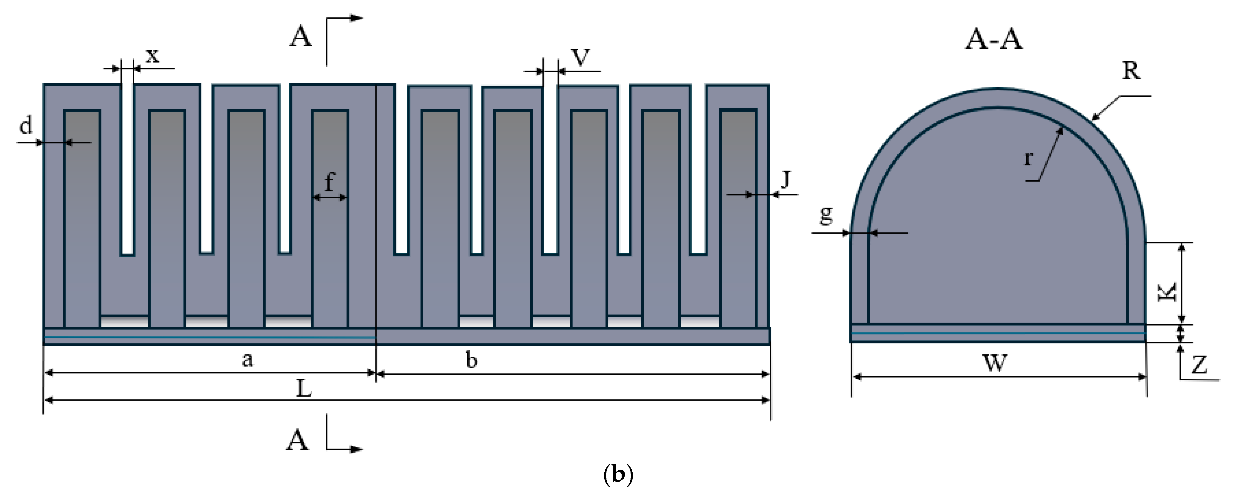
2.2. Structural Design

Based on the grasping characteristics of human fingers, the proximal phalanx requires greater rigidity to ensure grasping stability, while the middle and distal phalanx need stronger deformation ability for fingertip grasping or to enhance enveloping ability. For the biomimicry of finger functions, an elastic steel sheet is embedded within the constraint layer of the finger root actuator, with the finger structure illustrated in Figure 2a. The role of the steel sheet is (1) To solve the problem of insufficient deformation resistance of the soft finger and improve the load-bearing capacity and structural stability of a soft finger. (2) The rebound response of the elastic steel sheet is used to improve the grasping efficiency. Both actuators adopt a D-shaped cross-sectional design, as shown in Figure 2b, with each dimension’s corresponding values listed in Table 1. The air pipes of both actuators are side-connected, allowing them to operate independently or inflate together. When gas enters, the chamber inflates and expands axially. Simultaneously, the constraint layer at the bottom restricts this stretching, creating a discrepancy in deformation between the flexible layer and the constraint layer. This difference in deformation causes the structure to bend.

2.3. Manufacturing of Soft Fingers

The manufacturing of soft fingers includes three parts, fingertip deformation layer, finger root deformation layer, and finger constraint layer, which are produced using the corresponding 3D-printed (PLA material) [26] mold (Figure 3). The fabrication process is detailed as follows: (1) Inject silica gel (Ecoflex 0030; Smooth-On, Macungie, PA, USA; Viscosity:3000 mPa·s) into the fingertip and finger root mold. Form the fingertip deformation layer and finger root deformation layer by curing at room temperature for 6 h. (2) Inject silica gel into the mold of the constraint layer, pre-cure for 10 min, place an elastic steel sheet (Type 316L stainless steel, Shaanxi Shengyuan Steel Co., Ltd., Xi’an, China), adjust the position of the steel sheet so that it is placed at one end of the mold’s interior, and then inject silica gel to cover the steel sheet and fill the mold of the constraint layer. Then, cure for 6 h to form a constraint layer. (3) Use silicone adhesive to bond the fingertip and root deformation layers together and then connect it to the constraint layer to form a complete soft finger. The final soft finger is shown in Figure 4.

3. Establishment of Theoretical Model of Soft Finger Bending

The soft finger matrix is made of a hyperelastic material, which exhibits significant deformation and nonlinear behavior. Before analyzing the soft finger, a suitable constitutive model must be chosen. Commonly used models include the Mooney-Rivlin, Yeoh, Neo-Hookean, and Ogden models. Then, using principles such as moment balance and virtual work, the interactions among the air cavity of the finger root actuator, the air cavity of the fingertip, the overall bending angle of the finger, and the internal air pressure are analyzed.

3.1. Selection of Constitutive Model

The Yeoh model offers easy convergence and high accuracy in analyzing the large deformation of silica gel, with relevant parameters obtainable via uniaxial tensile tests. At present, the Yeoh model has become the first choice for analyzing the deformation of silica gel, so the Yeoh model is selected as the constitutive model of silica gel material. Assuming that the silicone rubber material exhibits isotropic and incompressible properties, its constitutive relationship is derived from stress–strain theory and formulated using the general expression of the strain energy density function W [27]:
W = ( I 1 , I 2 , I 3 ) = i = 1 N C i 0 ( I 1 3 ) i
W = ( I 1 , I 2 , I 3 ) I 1 = λ 1 2 + λ 2 2 + λ 3 2 I 2 = λ 1 2 λ 2 2 + λ 2 2 λ 3 2 + λ 3 2 λ 1 2 I 3 = λ 1 2 λ 2 2 λ 3 2
where I 1 , I 2 , I 3 is the first, second, and third invariants of the deformation tensor, λ i is the principal strain ratio in all directions [28], ε i is the principal strain, and W is the strain energy density function.
As the silica gel material is isotropic and incompressible throughout all directions, there is I 3 = 1 . Since the silica gel will become thinner while being stretched in the circumferential direction, it is presumed that no deformation occurs in the silica gel within the circumferential direction so λ 3 = 1 [28]. Consequently, we can obtain:
λ 1 2 = 1 λ 2 2
Substitute Equation (3) into Equation (2) to obtain:
I 1 = I 2 = λ 1 2 + 1 λ 2 2 + 1
Based on the classic binomial parameter form of the Yeoh model, by incorporating Equation (4) into the conventional binomial parameter form, the strain energy density function model is represented as:
W = C 10 ( I 1 3 ) + C 20 ( I 1 3 ) 2 = C 10 ( λ 1 2 + 1 λ 1 2 2 ) + C 20 ( λ 1 2 + 1 λ 1 2 2 ) 2 = C 10 ( λ 1 2 1 λ 1 2 ) 2 + C 20 ( λ 1 2 1 λ 1 2 ) 4
where C 10 and C 20 are material coefficients for silicone, which can be obtained through uniaxial tension testing [27] C 10 = 0.11 , C 20 = 0.02 .
Based on the relationship between strain energy and stress, the stress–strain relationship in this direction can be acquired by differentiating the strain energy density function with respect to the principal elongation ratio:
σ i = W λ i = W I 1 I 1 λ i + W I 2 I 2 λ i + W I 3 I 3 λ i

3.2. Bending Model of Fingertip Actuator

Throughout the deformation procedure of the fingertip actuator, the central angle corresponding to the deformation of each cavity remains identical. Thus, the central angle associated with the overall bending of the fingertip actuator can be regarded as the summation of the bending central angles of each individual cavity. Consequently, the bending angle of the fingertip actuator is equivalent to the product of the bending angle of a single cavity and the total number of cavities. Figure 5 illustrates the front view and cross-sectional structure of a single airbag of the fingertip actuator. Under the assumptions that the bending deformation of the fingertip actuator is not influenced by its own weight or external forces, the silicone material is incompressible, and the work performed by the internal air pressure p is entirely converted into the stored potential energy of the actuator, the principle of virtual displacement leads to the following conclusion:
P d V 2 ι = V r d W
where P is the internal air pressure applied in the chamber, W is the strain energy density function, V r is the volume of the silica gel material, and V 2 ι is the volume of the air chamber of a single airbag after deformation.
Because the silica gel material is incompressible, the volume of the material remains unchanged before and after deformation. Therefore, the volume of silica gel material can be expressed as:
V r = V 1 V 2 = w k + z u + 2 e + π 2 u + 2 e R 2 k s u + π 2 r 1 2 u
where V 1 is the total volume of a single airbag before deformation, V 2 is the volume of the air chamber of a single airbag before deformation.
The volume of the air chamber of a single airbag after deformation:
V 2 ι = V 1 ι V r = V 1 1 + λ V r
where V 1 ι is the total volume of a single airbag after deformation.
λ represents the axial elongation of a single airbag [29] and can be expressed as:
λ = θ sin θ
where θ is the central angle corresponding to a single airbag after deformation.
Differentiating both sides of Equation (7) with respect to θ , can obtain:
P d V 2 ι d θ = V r d W d θ
Notes: d V 2 ι d θ = V 1 sin θ θ cos θ sin 2 θ , d W d θ = 2 λ d λ d θ 1 1 λ 4 C 10 + 2 C 20 λ 1 λ 2
Substituting Equations (8)–(10) into Equation (11) and simplifying can obtain:
P = sin 2 θ V r V 1 sin θ θ cos θ d W d θ = w k + z u + 2 e + π 2 u + 2 e R 2 k s u π 2 r 1 2 u sin 2 θ u + 2 e sin θ θ cos θ π 2 R 2 + w k + w z d W d θ
In Equation (12), d W d θ can be expressed as a function of θ only. Therefore, the equation contains only two variables, P and θ . Once the driving air pressure P 2 is known, the corresponding bending angle θ 2 of a single airbag can be calculated. Subsequently, the mapping relationship between the overall bending angle θ q of the fingertip actuator and the driving air pressure P 2 can be derived based on the number of chambers. Where n is the number of cavities in the tip actuator ( n = 5 ).
θ q = n θ 2 ( P 2 )

3.3. Finger Root Actuator Bending Model

From Equation (6), it can be inferred that the connection between the axial stress of the finger root actuator and the principal elongation ratio is as follows:
σ 1 = W λ 1 = W I 1 I 1 λ 1 + W I 2 I 2 λ 2 + W I 3 I 3 λ 3 = 2 C 10 ( λ 1 1 λ 1 3 ) + 4 C 20 ( λ 1 2 + 1 λ 1 2 2 ) ( λ 1 1 λ 1 3 ) = 2 ( λ 1 1 λ 1 3 ) C 10 + 2 C 20 ( λ 1 1 λ 1 ) 2
Simplifying the above equation and neglecting terms of second order and higher can obtain:
σ 1 = 8 C 10 ( λ 1 1 )
λ 1 = θ sin θ
where λ 1 is the axial principal elongation ratio of the finger root actuator, σ 1 is the axial stress of the finger root actuator, and θ is the central angle corresponding to the bending of the finger root actuator.
Under the internal air pressure drive, the root actuator produces bending deformation. If the influence of the gravity of the actuator is not considered, when the bending reaches a stable state, it can be seen from the torque balance principle [30,31] that the propulsive torque generated by the actuating air pressure equals the sum of the resistance torque from the silicone’s tensile stress and the elastic force of the flexible steel sheet. The torque diagram is shown in Figure 6, and the cross-sectional structure of the finger root actuator is depicted in Figure 7.
The schematic diagram of torque is analyzed, and it can be obtained according to the principle of torque balance:
M = M 1 + M 2 + M 3
The bending driving torque M generated by the internal air pressure P is given by:
M = P 0 k 1 s z d z + P 0 π d θ 0 r 1 ( r sin θ + k 1 ) r d r
Assuming that the tensile stress σ 1 generated under the action of the driving air pressure P is uniformly distributed, the resistive torque M 1 generated by the tensile stress in the actuator’s deformation layer can be formulated as:
M 1 = 2 σ 1 0 k 1 g z d z + σ 1 0 π d θ r 1 R ( r sin θ + k 1 ) r d r
Similarly, the resistive torque M 2 produced by the tensile stress in the actuator’s constraint layer can be expressed as:
M 2 = σ 1 0 k 2 w z d z + σ 1 0 k 2 w ( 3 2 k 2 + t ) d k
The bending deformation of the flexible steel sheet generates the corresponding bending stress β :
β = λ 1 E
where E is the elastic modulus of the flexible steel sheet.
The resistive torque M 3 resulting from the bending stress in the flexible steel sheet can be expressed as:
M 3 = β 0 t w ( k 2 + t 2 ) d t
Substituting the driving torque and resistive torque into the torque balance equation can get:
P 0 k 1 s z d z + 0 π d θ 0 r 1 ( r sin θ + k 1 ) r d r = σ 1 2 0 k 1 g z d z + 0 π d θ r 1 R ( r sin θ + k 1 ) r d r + 0 k 2 w z d z + 0 k 2 w ( 3 2 k 2 + t ) d k + β 0 t w ( k 2 + t 2 ) d t
In Equation (21), σ 1 can be expressed as a function of θ only, leaving two unknowns, P and θ , in the equation. Once the driving air pressure P 1  is known, the corresponding bending angle θ 1 of the finger root actuator can be determined. Subsequently, the mapping relationship between the bending angle θ P of the finger root actuator and the driving air pressure P 1 can be derived.
θ p = θ 1 ( P 1 )

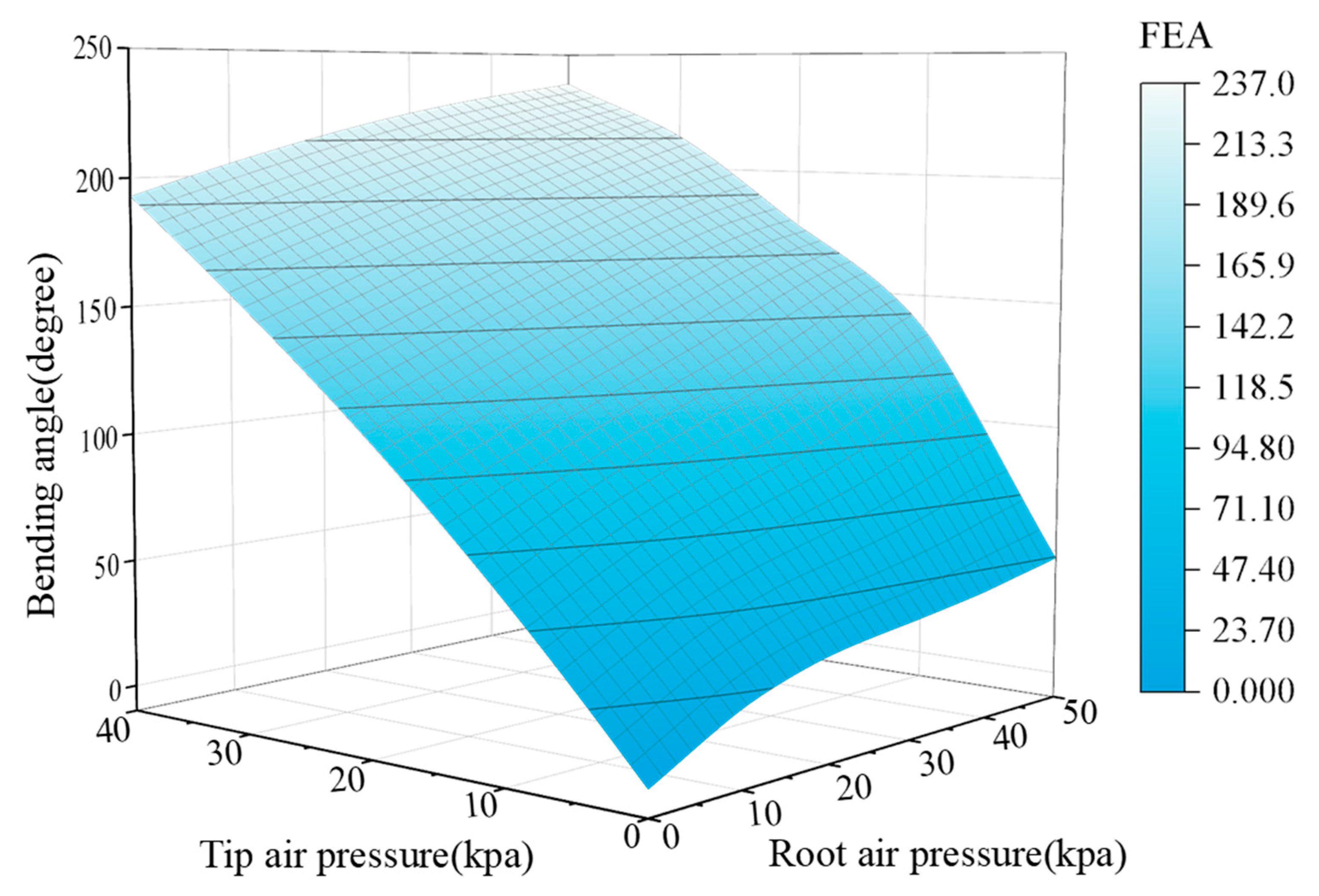
3.4. Analysis of the Overall Bending Angle of the Finger

The soft finger consists of a finger root actuator and a tip actuator. When the finger root actuator is inflated, and the tip is deflated, the root’s bending deformation enables the tip to move. When the finger root actuator is deflated, and the tip is inflated, the bending deformation of the fingertip actuator will not drive the bending deformation of the finger root actuator. Due to the inherent rigidity of the embedded flexible steel sheet, when both are inflated, the bending deformation of the fingertip actuator can be determined on the basis of the bending deformation of the finger root actuator. Hence, the total bending angle of the soft finger can be seen as the combined bending angles of the root actuator and the fingertip actuator, as illustrated in Figure 8.
Based on Equations (11) and (22), the total bending angle of the soft robotic finger is given by the following:
ω = θ p + θ q = θ 1 ( P 1 ) + n θ 2 ( P 2 )
where ω is the overall bending angle of the finger, θ p , θ q is the bending angles of the root and tip actuators, and P 2 , P 1 is the internal air pressure of the root and tip actuators.

4. Finite Element Simulation Analysis

During theoretical analysis, idealizations and presumptions regarding the soft actuator’s bending deformation were made, causing the computational outcomes to lack precision. To address this, finite element analysis using ABAQUS was employed for modeling. The procedure for pinpointing key parameters and their impact on deformation was thoroughly examined through simulations. Ultimately, the link between the actuator’s bending angle and driving pressure was analyzed via simulation.

4.1. Analysis Steps

(1)
Model the soft finger components in SolidWorks 2018 and save them in Parasolid format (.x_ t) for abaqus import.
(2)
Define material properties: the constitutive model is the Yeoh model, with the coefficient set to C 10 = 0.11 , C 20 = 0.02 . The steel sheet is an elastic material with a Young’s modulus of E = 193 GPa and a Poisson’s ratio of ν = 0.3. The density of the silica gel material is 1100 kg/m3.
(3)
Assemble the components.
(4)
Create a gravity load: the load type is gravity. The load direction is the negative direction of the Z-axis. The parameter “component 3” is −9810 mm/s2.
(5)
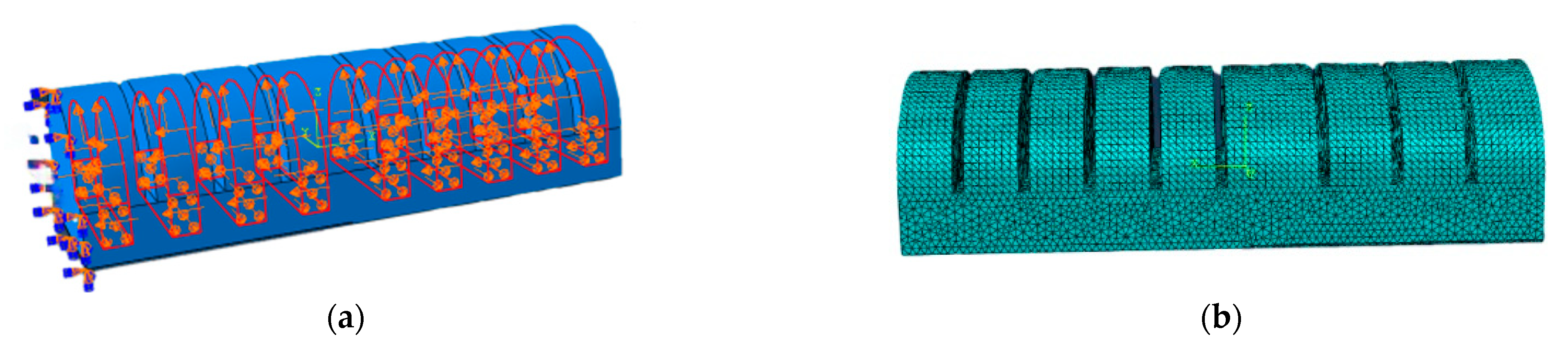
Define loads and boundary conditions: fix the end and apply internal pressure, as shown in Figure 9a.
(6)
Create self-contact interactions.
(7)
Set tangential and normal contact properties for the expansion wall surface.
(8)
Mesh with C3D10H elements, as shown in Figure 9b.
(9)
Create and submit the job for analysis.
Figure 9. Numerical simulation design. (a) Pressure load and boundary conditions. (b) Mesh division.
Actuators 14 00268 g009

4.2. Simulation Analysis of Key Parameters of Soft Finger

The geometric parameters significantly influence the deformation performance of the soft finger. To further improve the performance of soft pneumatic actuators and gain a better comprehension of their characteristics, an analysis and optimization of the key parameters of the soft finger were conducted. The analysis of these parameters was performed using Abaqus simulation. The key parameters (j, d, v, z, t) are illustrated in Figure 10. The variable selections are as follows: (1) tip wall thickness (j): 2 mm, 1.5 mm, 1 mm; (2) root wall thickness (d): 2.5 mm, 2 mm, 1.5 mm; (3) cavity spacing (v): 2 mm, 1.5 mm, 1 mm; (4) restrictive layer thickness (z): 2.5 mm, 2 mm, 1.5 mm; (5) flexible steel sheet thickness (t): 0.5 mm, 0.3 mm, 0.1 mm.

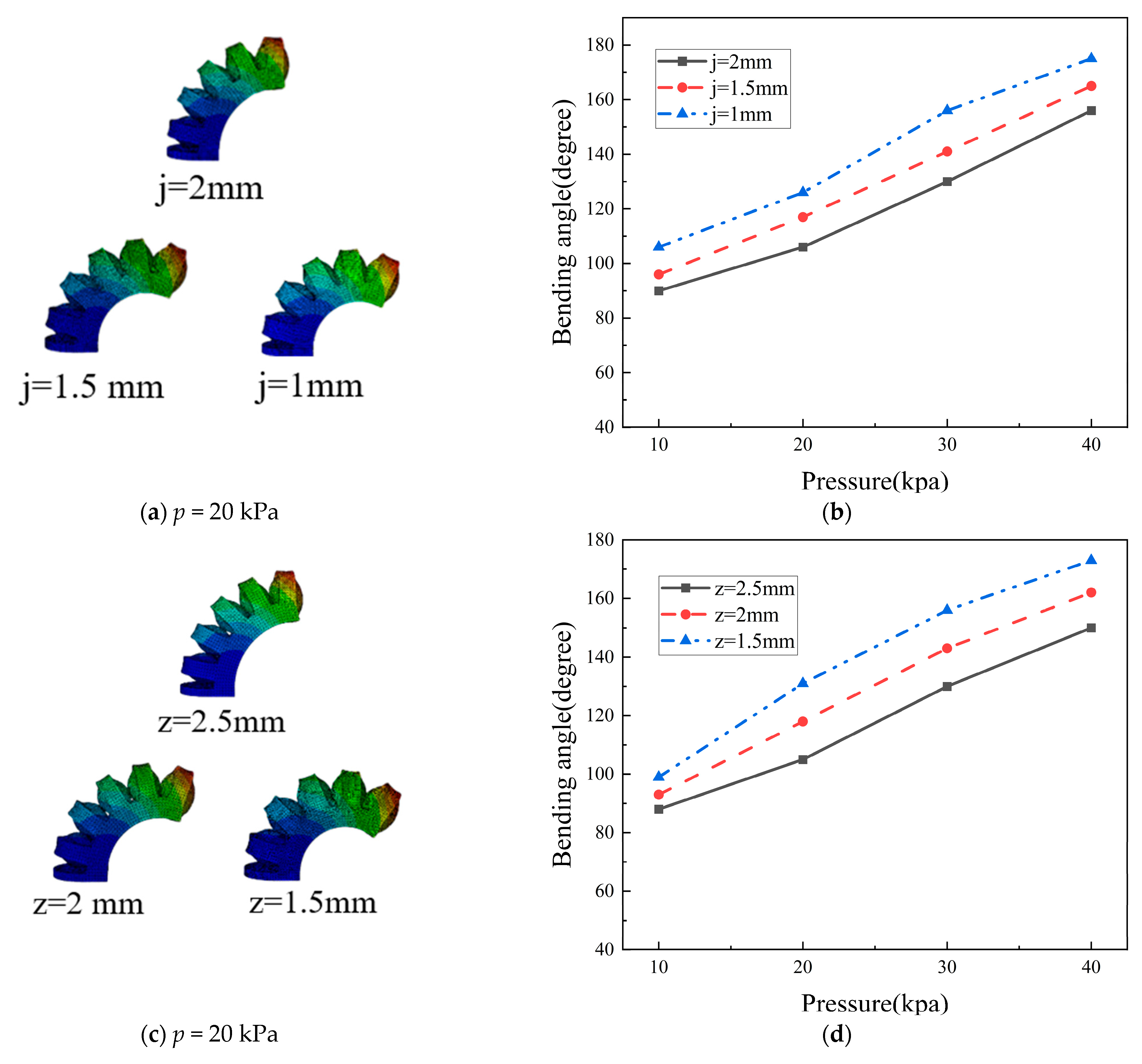
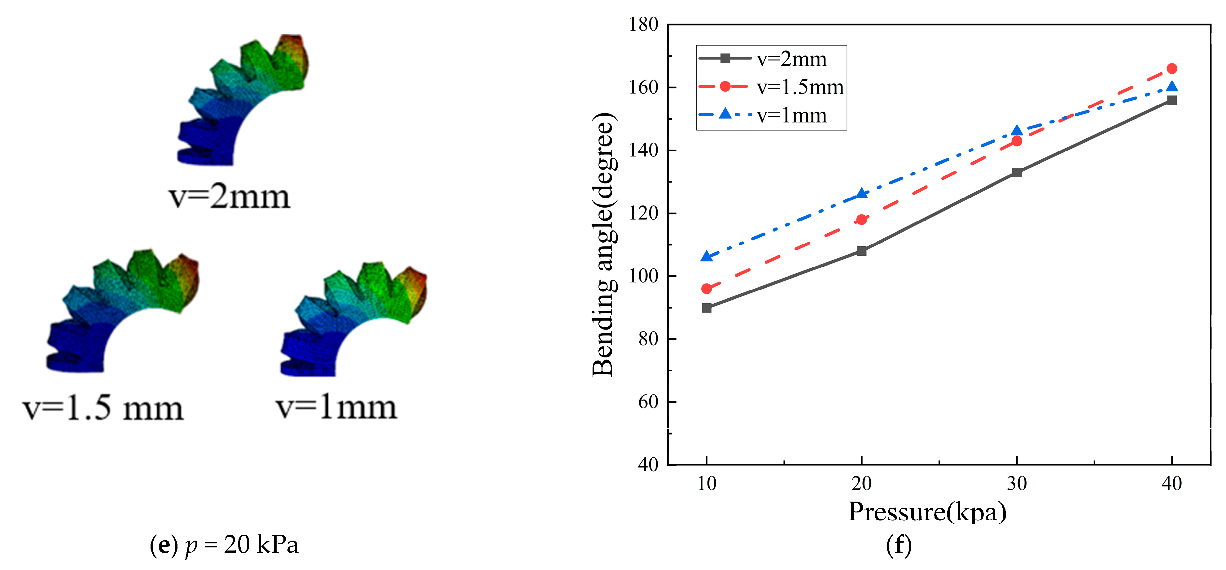
4.2.1. Parameter Analysis of the Tip Actuator

The deformation performance of the fingertip actuator is mainly influenced by tip wall thickness (j), cavity spacing (v), and restrictive layer thickness (z). Using the control variable method, the optimal structural parameters were determined by comparing the simulation results in the pressure range of 0–40 kPa.
1. Tip wall thickness. Figure 11a shows the bending deformation of models with different wall thicknesses under 20 kPa pressure. Figure 11b illustrates a linear correlation between the bending angle and applied pressure, which is inversely proportional to wall thickness. Thicker walls reduce flexibility and bending performance, while thinner walls improve the deformation but risk localized ballooning and damage. The optimal wall thickness is 1.5 mm.
2. Restriction layer thickness. Figure 11c shows the bending deformation of simulation models with different restrictive layer thicknesses under 20 kPa pressure. Figure 11d indicates that the bending angle is inversely related to the thickness of the constraint layer. A thin layer causes radial expansion, weakening axial elongation restriction and leading to the inability of the actuator to bend, while a thick layer reduces flexibility and affects bending performance. Therefore, the restrictive layer thickness must be optimized. After comprehensive consideration, 2 mm is determined to be the optimal thickness.
3. Cavity spacing. Figure 11e illustrates the flexural deformation of three simulation models with varying cavity spacings under 20 kPa internal pressure. Figure 11f shows the correlation between applied pressure and bending angle for these models. Results indicate that small cavity spacing makes the soft actuator overly sensitive, causing excessive bending at low pressures and challenging precise control. Large spacing between air cavities reduces sensitivity and requires higher pressure for bending. Therefore, the optimal cavity spacing is determined to be 1.5 mm to balance sensitivity and controllability.

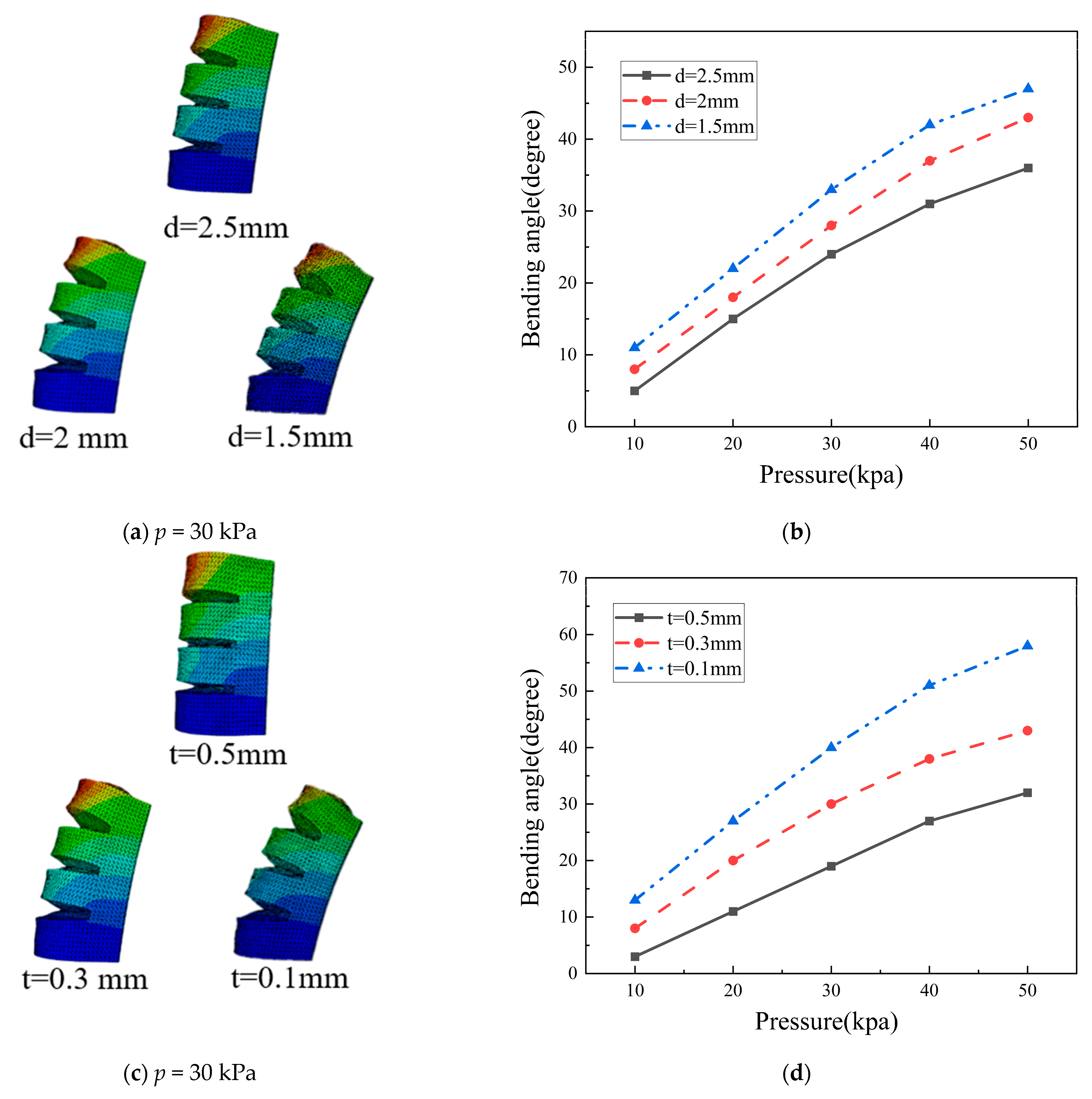
4.2.2. Parameter Analysis of the Finger Root Actuator

Simulation analysis identified three key parameters of the fingertip actuator: expansion wall thickness, chamber spacing, and constraint layer thickness. Finger root actuators and fingertip actuators have slightly different structures: (1) different wall thicknesses; (2) a flexible steel sheet embedded in the root actuator’s constraint layer. This study focuses on the influence of expansion wall thickness and steel sheet thickness on deformation performance with an internal air pressure of 0–50 kPa.
1. Root wall thickness. The analysis method for the finger root actuator is consistent with that of the fingertip actuator. Due to the embedded steel sheet, higher air pressure is needed for bending, leading to three wall thickness designs: 1.5 mm, 2 mm, and 2.5 mm. The bending deformation under 30 kPa is shown in Figure 12a, and the linear relationship between air pressure and bending angle is shown in Figure 12b. A thicker wall reduces bending performance, while a thinner wall causes local ballooning and potential rupture. Based on these findings, 2 mm was chosen as the optimal wall thickness.
2. Steel sheet thickness. At 30 kPa, the flexural deformation of models with three different steel sheet thicknesses is shown in Figure 12c, and the direct proportionality between air pressure and bending angle is depicted in Figure 12d. The thinner steel sheet in the constraint layer leads to greater bending deformation. However, to prevent flexural deformation of the fingertip actuator from affecting the bending behavior of the root actuator, the root actuator must maintain sufficient stiffness so the steel sheet cannot be too thin. Conversely, a thicker steel sheet significantly reduces bending deformation. Considering these trade-offs, a steel plate thickness of 0.3 mm was chosen as optimal.

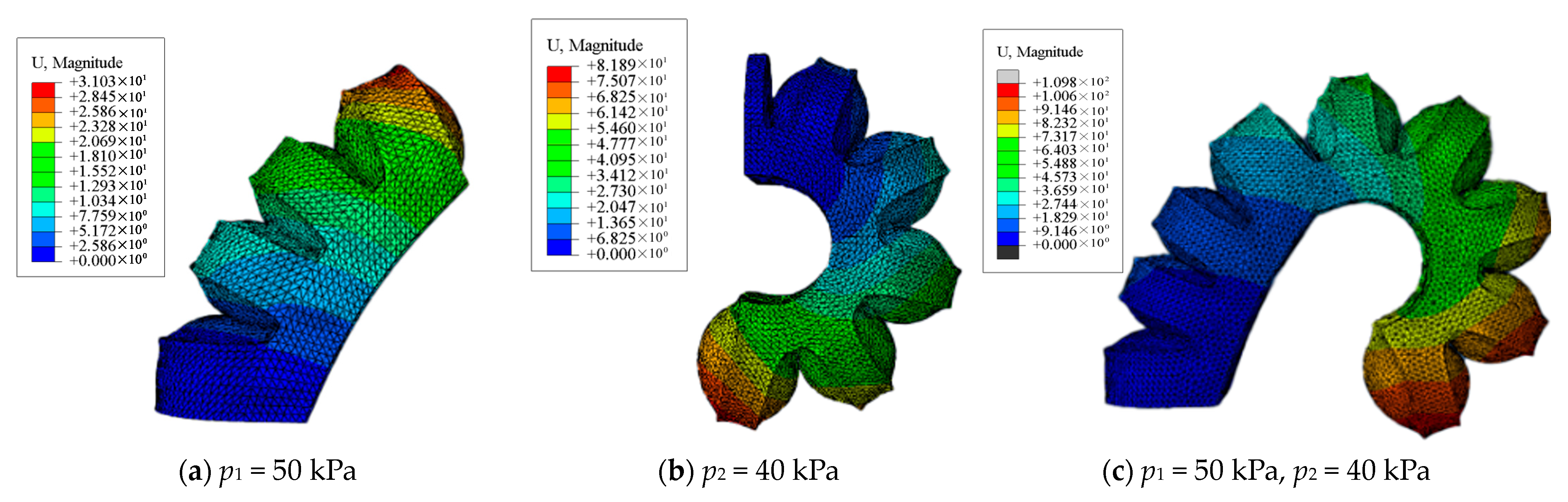
4.3. Simulation Analysis of the Overall Deformation of the Finger

The fingertip actuator features a wall thickness of 1.5 mm, a constrained layer thickness of 2 mm, and a chamber spacing of 1.5 mm. Meanwhile, the finger root actuator has a wall thickness of 2 mm and incorporates a steel sheet of 0.3 mm. The fingertip actuator operates at 0–40 kPa, while the finger root actuator operates at 0–50 kPa. At 40 kPa, the fingertip actuator bends to 190° (Figure 13b). At 50 kPa, the finger root actuator bends to 47° (Figure 13a). At maximum designed air pressures, the robotic finger reaches a maximum bending angle of 237° (Figure 13c). The 3D deformation contour map in Figure 14 provides a comprehensive visualization of the soft finger’s deformation characteristics.

5. Experimental Testing and Analysis

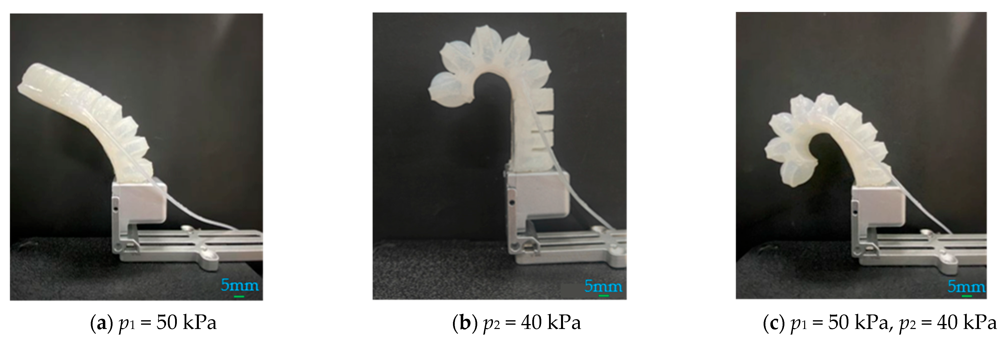
5.1. Bending Deformation Capability Testing of the Soft Finger

To validate the bending characteristics predicted by theoretical and simulation analyses, experimental tests were conducted using the platform shown in Figure 15, with equipment including an automatic blower, manual pneumatic valve, digital angle gauge, pressure gauge, soft fingers, and base. The experiments are divided into three parts: (1) inputting air pressure only to the fingertip actuator; (2) inputting air pressure only to the finger root actuator; (3) both inflating at the same time. Figure 16a shows the soft finger bending at 44 degrees when the finger root actuator is inflated to its maximum design pressure (50 kPa). Figure 16b shows a bending angle of 186 degrees when the fingertip actuator is inflated to its maximum design pressure (40 kPa). When both were inflated to their maximum design pressures, the total bending angle reached 230 degrees (Figure 16c).
Experimental results were compared with theoretical and simulation results (Figure 17). There is a relative error of 5.74% between the experimental and theoretical bending deformation [relative error = (absolute error/theoretical value) × 100%, absolute error = |experimental value − theoretical value|]. The experimental results are somewhat lower than the theoretical and simulation results, mainly due to the following: (1) friction between the soft finger and base during bending; (2) limited control accuracy of the pneumatic valve’s output pressure; (3) manufacturing errors in the soft finger structure. Despite discrepancies, the trends of experimental, theoretical, and finite element analysis results are generally consistent. This evidence indicates that the theoretical model and finite element simulation results can be utilized to estimate the bending angle of the soft finger.

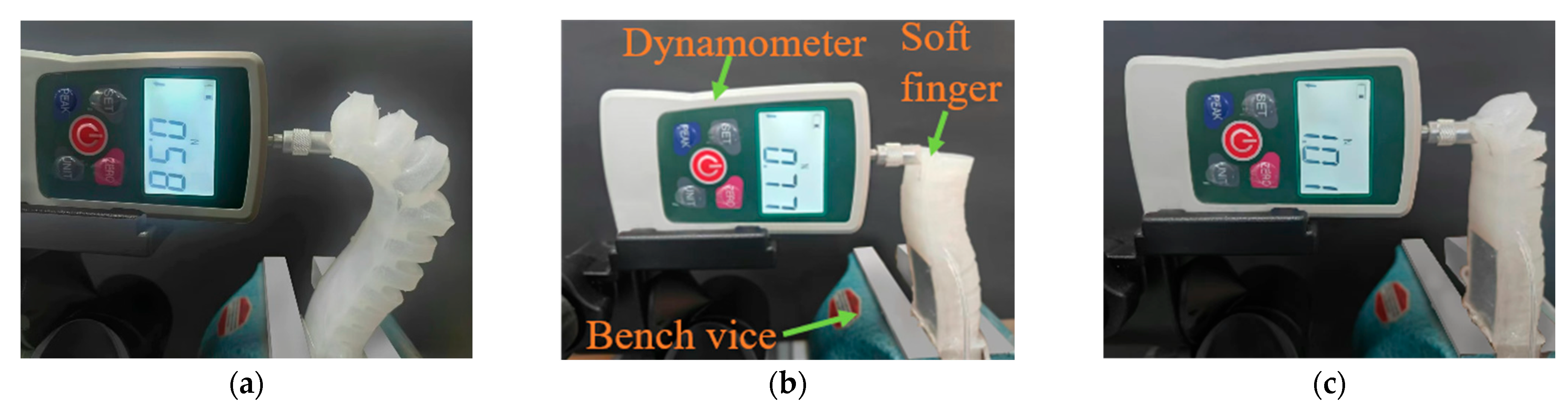
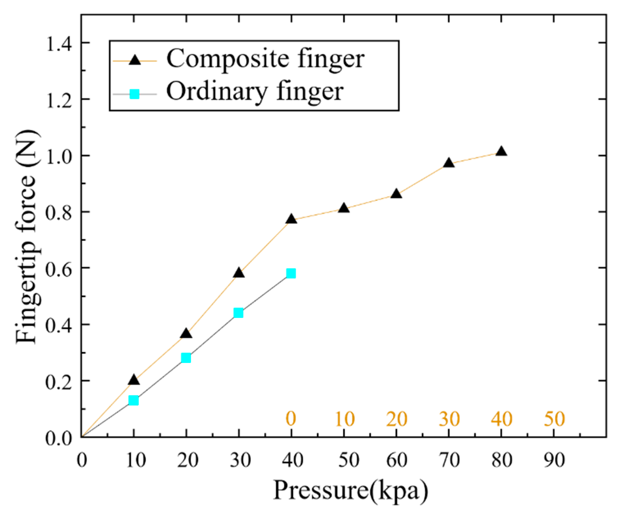
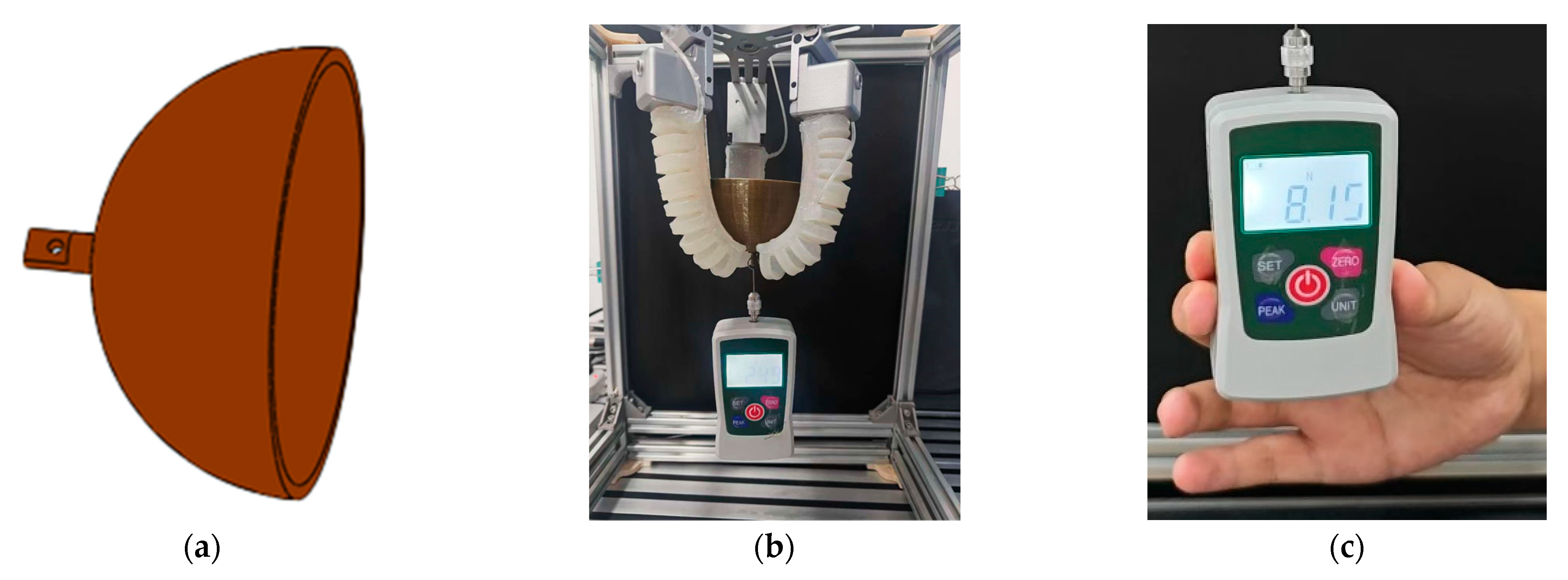
5.2. Fingertip Force Testing of the Soft Robotic Finger

The fingertip force refers to the maximum output force at the end of a soft finger under a specific air pressure. It is an important index for measuring the load-bearing capacity of the soft manipulator. In order to study the fingertip force of the composite finger, an ordinary soft finger driven by a single air chamber was made of the same size and embedded in a flexible steel sheet in the limiting layer. For quantitative comparison, the input air pressure for the two fingers was set to 40 kpa. A Heng Tong HT-1002 digital force gauge (resolution: 0.01 N) gauge was used for precise measurement. The fingertip force of the ordinary soft finger after inflation was 0.58 N (Figure 18a).
During the inflation of the composite soft finger, 40 kpa gas was first charged into the root air chamber. The fingertip force was 0.77 N (Figure 18b). Then, 40 kpa gas was introduced into the tip air chamber. The fingertip force was 1.01 N (Figure 18c). The contrasting curve of the fingertip force between the two types of fingers relative to internal air pressure is shown in Figure 19. Composite soft fingers exhibit much greater fingertip force compared to ordinary soft fingers, and the extra fingertip force was equivalent to 42.57% of the force of its own fingertip. This confirms that the embedded steel sheet enhances fingertip force, which in turn implies a higher load-bearing capacity.

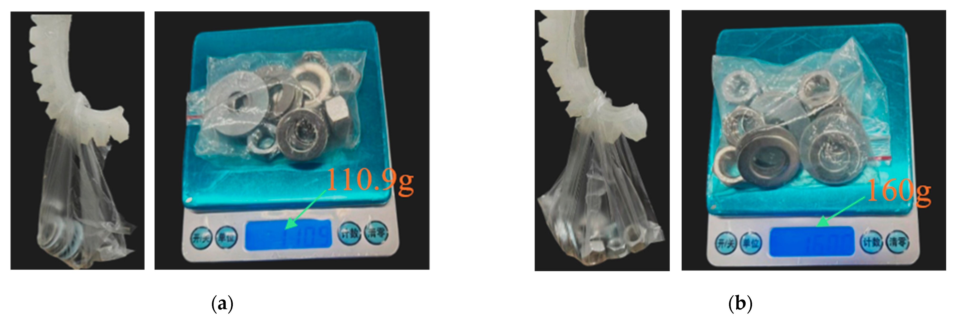
5.3. Hook Quality Test

To further study the enhancement of load-bearing capacity by the embedded steel sheet structure, a hooking quality test was conducted, as it directly reflects load-bearing capacity. The hooking quality was used to quantify the load-bearing capacity. Using the same comparative method, the test added weights (small nut: 10 g, large nut: 15.2 g, small washer: 4 g, large washer: 6 g) to a transparent bag until a threshold mass was reached, allowing the weight to be held for 10 s without dropping. A high-precision balance (Figure 20) measured the hooking quality. At the same air pressure (40 kpa), the composite finger could hold 160 g, while the ordinary finger could only hold 110 g. Experimental findings indicate that, at the same air pressure, the load-bearing capacity of the composite soft finger is much greater than that of the ordinary soft finger, with an extra load-bearing capacity equivalent to 31.25% of the composite finger’s own load-bearing capacity. Comparative experiments have confirmed that the embedded steel sheet structure greatly increases the composite finger’s load-bearing capacity.

6. Performance Test of Soft Manipulator

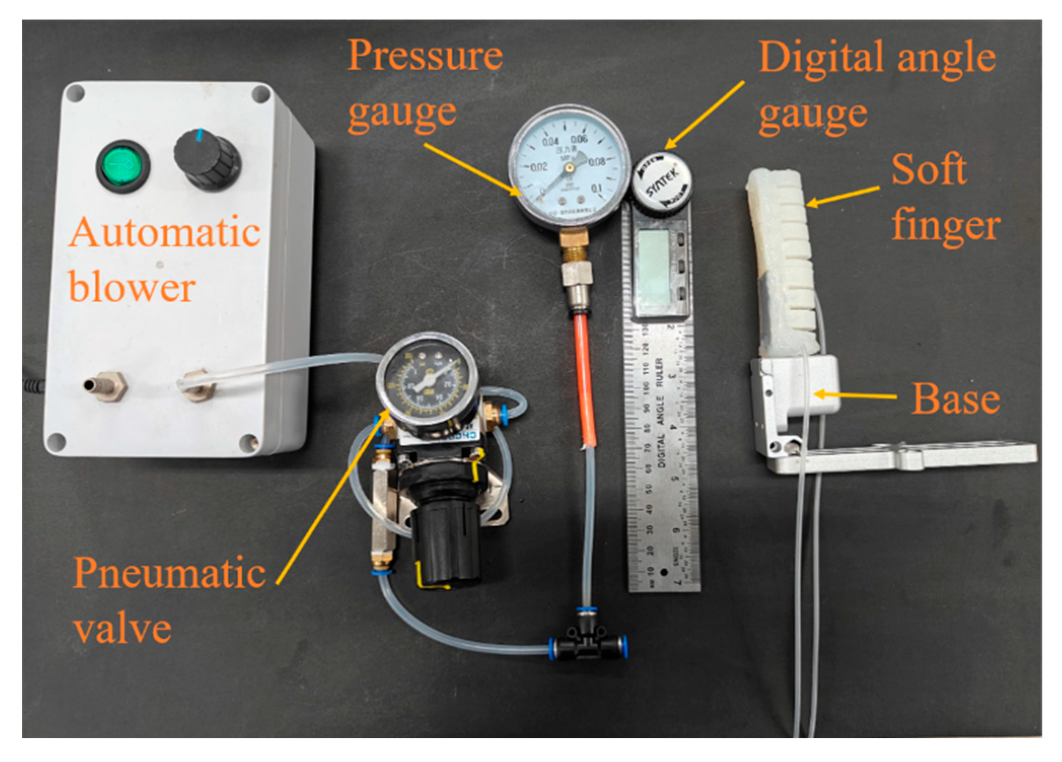
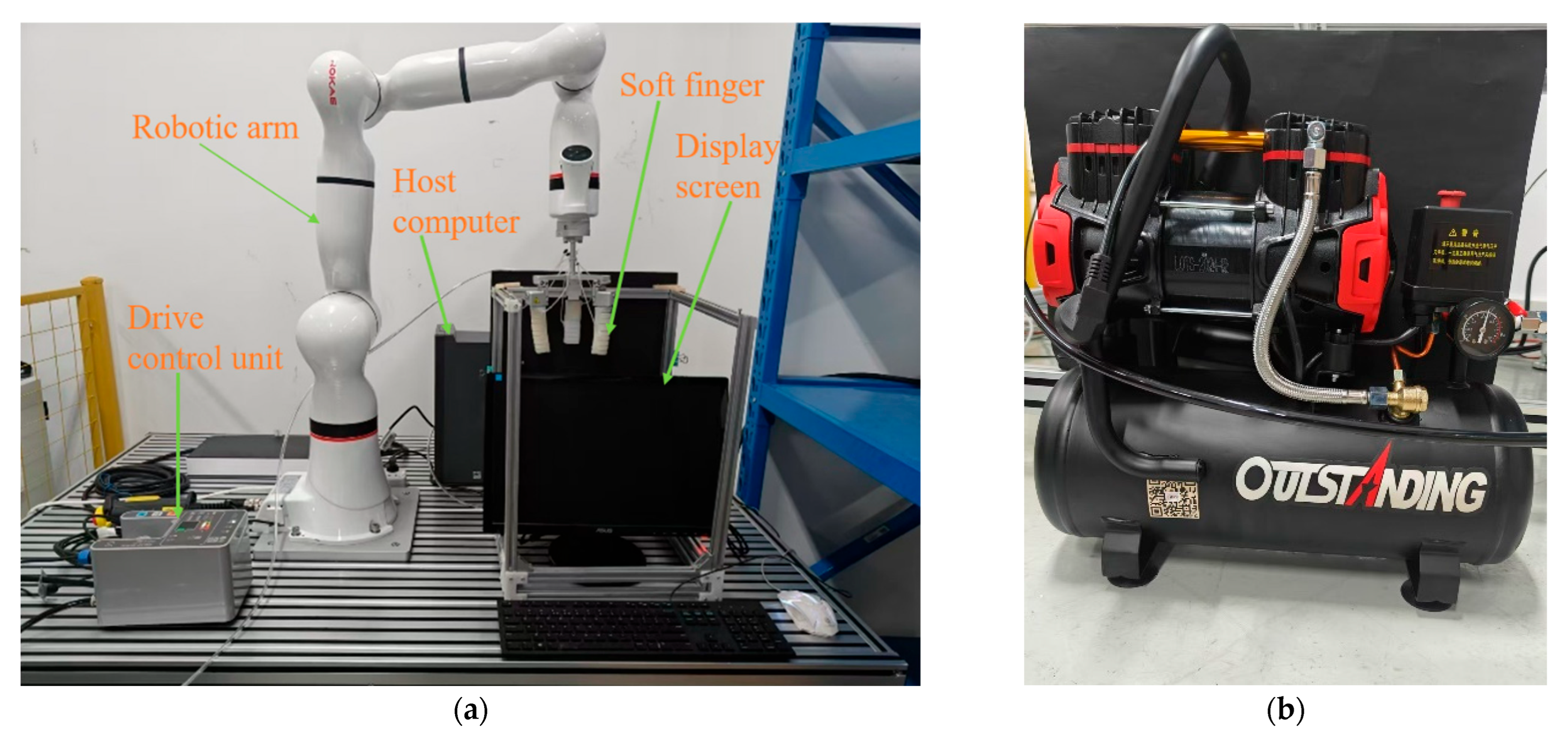
6.1. Construction of the Experimental Platform

The setup for testing the soft robotic hand is depicted in Figure 21a. The main components include a robotic arm, a host computer, a display screen, the IPCU2 drive control unit, and three soft fingers. The three fingers were installed into the three-finger mounting module that came with the robotic arm, forming a functional robotic hand. Each finger is adjustable for grasping objects of various diameters and shapes. An air compressor (Figure 21b) supplies the air pressure. It uses an IPCU2 drive control unit to deliver a constant air pressure ranging from −90 kPa to 300 kPa, with a control precision of ±0.5 kPa, ensuring precise setting of the desired output pressure. The actuator’s motion response process is as follows: a compressor supplies high-pressure air, which travels through a pneumatic tube to the drive control unit. The drive control unit is connected via another pneumatic tube to the internal air chamber of the actuator. It can regulate the output air pressure. When there is a sudden change in the output pressure, the actuator’s air chamber can quickly detect this pressure variation. The actuator, made of soft silicone rubber with high flexibility and deformability, can swiftly respond to pressure changes. Upon pressure increase, the air chamber expands, causing the deformation layer of the actuator to bend. Conversely, when the pressure decreases, the air chamber contracts, and the actuator either returns to its original shape or reduces its degree of bending.

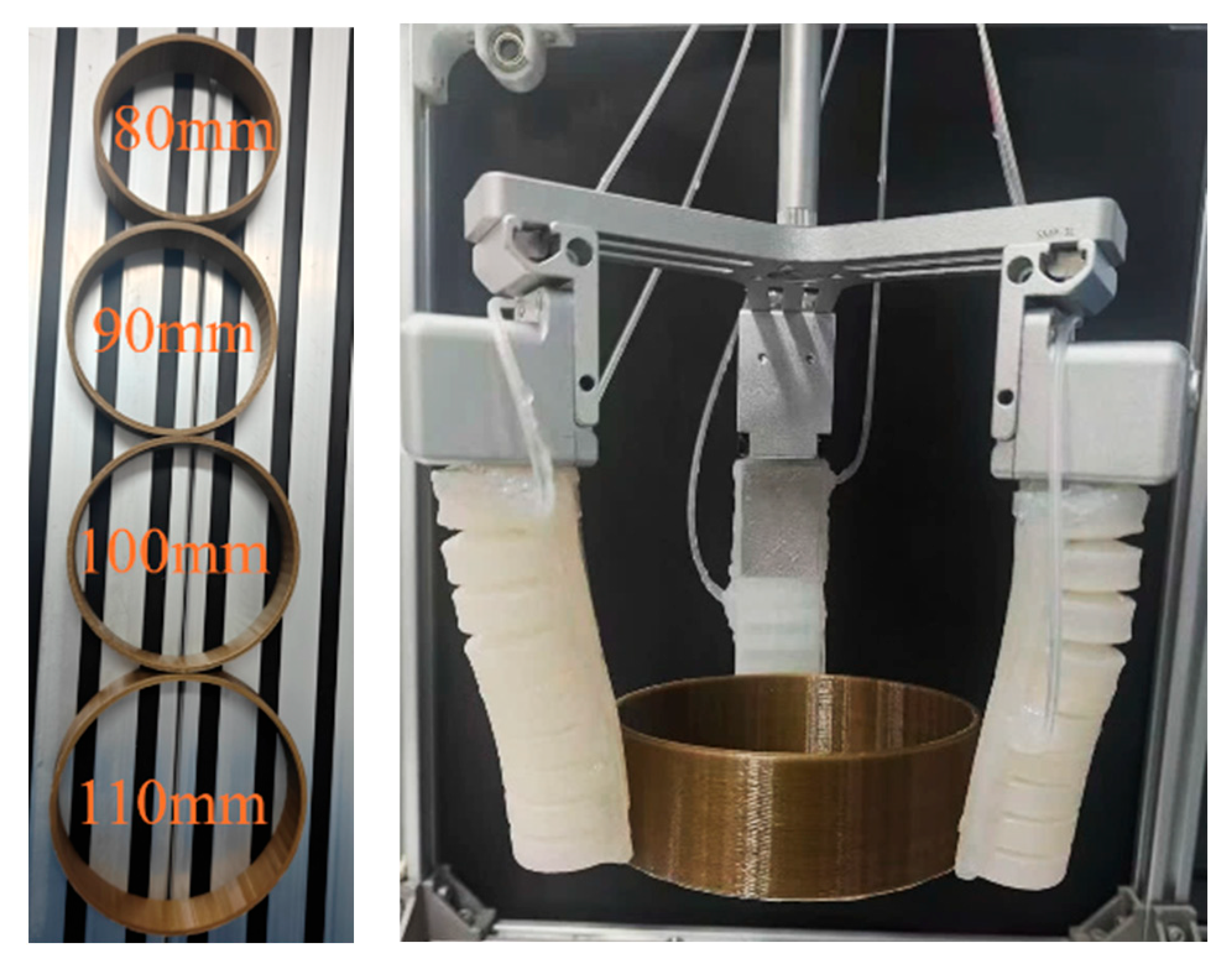
6.2. Gripping Diameter Test

The grasping diameter is a critical indicator for assessing the performance of soft robotic grippers, demonstrating the range of object sizes the gripper can effectively handle. To evaluate this, four 3D-printed circular rings with diameters of 110 mm, 100 mm, 90 mm, and 80 mm were used (Figure 22). The relative position of the three fingers can be adjusted adaptively during the experiment, and the largest diameter of the ring that could be stably grasped was 110 mm. Therefore, based on these experimental results, the maximum grasping diameter of this robotic hand is 110 mm.

6.3. Gripping Force Testing

Grasping force is the key index to evaluate the performance of the soft manipulator and indicates the soft manipulator’s capability. To accurately measure the grasping force, the gripping diameter of the soft manipulator was set to a common value of 60 mm. To facilitate the measurement of grasping force, a special force-measuring device (material: 3D printing resin) was designed, as shown in Figure 23a. This device consists of a semi-circular shell with a main wall thickness of 3 mm, featuring a thin plate protruding from the bottom. A central hole in this plate allows for a secure connection to a dynamometer. During the testing process, all three soft fingers operate at their maximum working pressure. After stably gripping the semi-circular force measurement device, as shown in Figure 23b, the robotic hand gradually increases the pulling force to pull the dynamometer vertically downward from the center of the gripper. The reading on the dynamometer is carefully observed, and the pulling force required to detach the semi-circular force measurement device from the gripper is recorded as the maximum grasping force, as shown in Figure 23c. Experimental results have demonstrated that the maximum effective grasping force of this soft robotic hand is approximately 8.15 N.

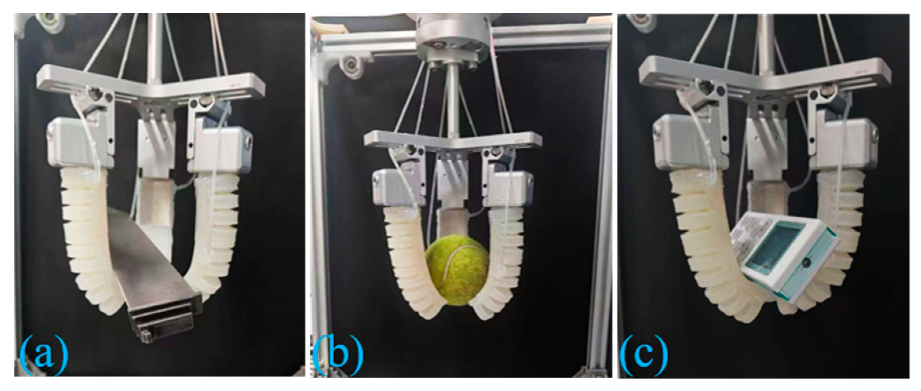
6.4. Physical Object Grasping Applications

To assess the grasping performance of the soft robotic gripper, tests were performed on items varying in shape, size, and weight. Table 2 shows the objects grasped and the success rate of 60 grab attempts, where successful grasping is defined as holding the object stably for at least 10 s without slipping or dropping.
In addition to the hook function, the soft manipulator mainly has two working modes: pinch grab and envelope grab. Package grabbing: the contact area with the object is larger so as to achieve more reliable and stable grabbing (Figure 24b).Pinch grabbing: the object is clamped by the fingertip force of three fingers, which is suitable for small mass objects such as slender rods (Figure 25e).
As shown in Figure 24, the manipulator can grasp small industrial products such as small turbine blades. As shown in Figure 25, the manipulator can grasp objects with irregular shapes, such as glasses, hand cream, water bottles, wine glasses, and objects with regular shapes, such as oranges, indicating its good adaptability. It can be used in working environments where the traditional manipulator cannot meet the requirements of daily life and industrial production, such as vegetable classification, picking and placing of fragile or damaged items, and picking of items with irregular shapes. In addition, soft manipulators have many advantages, such as low production and maintenance costs, giving broad application prospects in many fields.

7. Conclusions

This paper introduces a composite air chamber bionic soft finger actuator inspired by human fingers. Finger characteristics: (1) The dual chamber structure makes the movement of the soft grip more in line with the natural bending characteristics of human fingers and improves the flexibility and adaptability of grasping. (2) The flexible steel sheet is embedded in the strain constraint layer of the root actuator. The above two points better solve the problems of single function and poor load-bearing capacity in the field of soft manipulators. Once the finger structure is designed, a theoretical model for finger bending is developed. The bending deformation of the soft finger is analyzed using the finite element method to identify the optimal structural parameters. Subsequently, an experimental platform is constructed to validate the bending characteristics of the finger, revealing that it exhibits greater fingertip force. Then, the grasping diameter, force, and hooking quality are explored. The hooking quality tests show that the load-bearing capacity of the composite finger has been significantly improved. Finally, a series of objects are grasped, which shows that the manipulator has good adaptability and broad application prospects.
The above considerations are relevant for the operation of the actuator under normal atmospheric pressure. The operation in a vacuum environment is also a topic worth exploring. In such conditions, the outgassing behavior of silicone rubber and the alteration of its superelasticity may modify deformation features, and the chamber could over-expand or even rupture due to excessive internal–external pressure differences. These assumptions indicate the key directions for future research: developing low-volatility vacuum-compatible elastomeric materials, improving sealing technology, and creating more pressure-resistant structures (such as multilayer composite wall structures). Although it has many advantages, it still needs to be improved in the following aspects: (1) Integrating flexible sensors into the soft fingers to provide sensory functions such as touch, temperature, vibration, and force, enabling the design of an intelligent soft robotic hand. (2) Although embedding a flexible steel sheet in the constraint layer of the proximal joint actuator improves the load-bearing capacity, it cannot adaptively adjust stiffness based on the weight of the target object. (3) Subsequent studies should take into account the adaptability to extreme environments (like vacuums) to address performance fluctuations caused by environmental parameter changes. Therefore, it is still an important task in the future to continue to improve the designed soft manipulator.

Author Contributions

Writing—original draft preparation, Y.C.; methodology, S.L.; software, S.W.; validation, D.Z.; formal analysis, W.D.; investigation, S.H.; data curation, M.S.; conceptualization, D.W. All authors have read and agreed to the published version of the manuscript.

Funding

This work was financially supported by the Natural Science Foundation of Shanghai, China, with grant number [23ZR1425600 and 24ZR1427200].

Data Availability Statement

The research data of this paper are all included in this paper, and no new data have been created.

Acknowledgments

The authors would like to thank Huang Shuai for his suggestions, thoughts, and experiments in the process of creation.

Conflicts of Interest

The authors declare no conflicts of interest.

References

  1. Flesher, S.N.; Downey, J.E.; Weiss, J.M.; Hughes, C.L.; Herrera, A.J.; Tyler-Kabara, E.C.; Boninger, M.L.; Collinger, J.L.; Gaunt, R.A. A brain-computer interface that evokes tactile sensations improves robotic arm control. Science 2021, 372, 831–836. [Google Scholar] [CrossRef] [PubMed]
  2. Zhang, J.; Ndou, W.S.; Ng, N.; Gaston, P.; Simpson, P.M.; Macpherson, G.J.; Patton, J.T.; Clement, N.D. Robotic-arm assisted total knee arthroplasty is associated with improved accuracy and patient reported outcomes: A systematic review and meta-analysis. Knee Surg. Sports Traumatol. Arthrosc. 2022, 30, 2677–2695. [Google Scholar] [CrossRef] [PubMed]
  3. Khalid, M.Y.; Arif, Z.U.; Ahmed, W.; Umer, R.; Zolfagharian, A.; Bodaghi, M. 4D printing: Technological developments in robotics applications. Sensor. Actuat. A Phys. 2022, 343, 113670. [Google Scholar] [CrossRef]
  4. Hao, Y.; Zhang, S.; Fang, B.; Sun, F.; Liu, H.; Li, H. A review of smart materials for the boost of soft actuators, soft sensors, and robotics applications. Chin. J. Mech. Eng. 2022, 35, 37. [Google Scholar] [CrossRef]
  5. Goh, G.D.; Goh, G.L.; Lyu, Z.; Ariffin, M.Z.; Yeong, W.Y.; Lum, G.Z.; Campolo, D.; Han, B.S.; Wong, H.Y.A. 3D printing of robotic soft grippers: Toward smart actuation and sensing. Adv. Mater. Technol. 2022, 7, 2101672. [Google Scholar] [CrossRef]
  6. Sparrman, B.; Du Pasquier, C.; Thomsen, C.; Darbari, S.; Rustom, R.; Laucks, J.; Shea, K.; Tibbits, S. Printed silicone pneumatic actuators for soft robotics. Addit. Manuf. 2021, 40, 101860. [Google Scholar] [CrossRef]
  7. Yap, Y.L.; Sing, S.L.; Yeong, W.Y. A review of 3D printing processes and materials for soft robotics. Rapid Prototyp. J. 2020, 26, 1345–1361. [Google Scholar] [CrossRef]
  8. Filippova, O.V.; Maksimkin, A.V.; Dayyoub, T.; Larionov, D.I.; Telyshev, D.V. Sustainable Elastomers for Actuators: “Green” Synthetic Approaches and Material Properties. Polymers 2023, 15, 2755. [Google Scholar] [CrossRef]
  9. Kim, M.S.; Heo, J.K.; Rodrigue, H.; Lee, H.T.; Pané, S.; Han, M.W.; Ahn, S.H. Shape memory alloy (SMA) actuators: The role of material, form, and scaling effects. Adv. Mater. Technol. 2023, 35, 2208517. [Google Scholar] [CrossRef]
  10. Chen, R.; Wu, L.; Sun, Y.; Chen, J.-Q.; Guo, J.-L. Variable stiffness soft pneumatic grippers augmented with active vacuum adhesion. Smart Mater. Struct. 2020, 29, 105028. [Google Scholar] [CrossRef]
  11. Silva, A.B.; Murcia, M.; Mohseni, O.; Takahashi, R.; Forner-Cordero, A.; Seyfarth, A.; Hosoda, K.; Sharbafi, M.A. Design of Low-Cost Modular Bio-Inspired Electric–Pneumatic Actuator (EPA)-Driven Legged Robots. Biomimetics 2024, 9, 164. [Google Scholar] [CrossRef] [PubMed]
  12. Han, P.; Lauder, G.V.; Dong, H. Hydrodynamics of median-fin interactions in fish-like locomotion: Effects of fin shape and movement. Phys. Fluids 2020, 32, 011902. [Google Scholar] [CrossRef]
  13. Zuo, Q.; Xu, Y.; Xie, F.; Fang, H.; He, K.; Zhong, Y.; Li, Z. Dynamic modeling of a novel kind of rigid-soft coupling biomimetic robotic fish. J. Intell. Robot. Syst. 2022, 105, 41. [Google Scholar] [CrossRef]
  14. Joyee, E.B.; Pan, Y. A fully three-dimensional printed inchworm-inspired soft robot with magnetic actuation. Soft Robot. 2019, 6, 333–345. [Google Scholar] [CrossRef]
  15. Zhai, Y.; De Boer, A.; Yan, J.; Shih, B.; Faber, M.; Speros, J.; Gupta, R.; Tolley, M.T. Desktop fabrication of monolithic soft robotic devices with embedded fluidic control circuits. Sci. Robot. 2023, 8, eadg3792. [Google Scholar] [CrossRef]
  16. Merces, L.; Ferro, L.M.M.; Thomas, A.; Karnaushenko, D.D.; Luo, Y.; Egunov, A.I.; Zhang, W.; Bandari, V.K.; Lee, Y.; McCaskill, J.S.; et al. Bio-Inspired Dynamically Morphing Microelectronics toward High-Density Energy Applications and Intelligent Biomedical Implants. Adv. Mater. 2024, 36, 2313327. [Google Scholar] [CrossRef]
  17. Zhang, M.; Pal, A.; Zheng, Z.; Gardi, G.; Yildiz, E.; Sitti, M. Hydrogel muscles powering reconfigurable micro-metastructures with wide-spectrum programmability. Nat. Mater. 2023, 22, 1243–1252. [Google Scholar] [CrossRef]
  18. Bezha, K.; Ito, K. Soft manipulator inspired by octopi: Object grasping in all anatomical planes using a tendon-driven continuum arm. Artif. Life Robot. 2023, 28, 96–105. [Google Scholar] [CrossRef]
  19. Pi, J.; Liu, J.; Zhou, K.; Qian, M. An octopus-inspired bionic flexible gripper for apple grasping. Agriculture 2021, 11, 1014. [Google Scholar] [CrossRef]
  20. An, S.-Q.; Li, W.-H.; Li, J.-H.; Zou, H.-L.; Deng, Z.-C. Tuning stiffness with granular chain structures for versatile soft robots. Soft Robot. 2023, 10, 493–503. [Google Scholar] [CrossRef]
  21. Li, X.; Zheng, T.; Sui, D.; Lin, N.; Zhang, Q.; Zhao, J.; Zhu, Y. A 3D printed variable cross-section pneumatic soft manipulator with high-precision positioning capability: Design and control implementation. Sens. Actuators A Phys. 2022, 342, 113644. [Google Scholar] [CrossRef]
  22. Li, J.; Luan, Z.; Wang, Y.; Huang, M.; Yan, J.; Wang, Y. Analysis modeling and experiment of bionic winding soft actuator inspired by plant tendrils. Smart Mater. Struct. 2023, 32, 035023. [Google Scholar] [CrossRef]
  23. Xiao, W.; Hu, D.; Yang, G.; Jiang, C. Modeling and analysis of soft robotic surfaces actuated by pneumatic network bending actuators. Smart Mater. Struct. 2022, 31, 055001. [Google Scholar] [CrossRef]
  24. Zhang, P.; Chen, W.; Tang, B. Design and feasibility tests of a lightweight soft gripper for compliant and flexible envelope grasping. Soft Robot. 2022, 9, 376–385. [Google Scholar] [CrossRef]
  25. Dunai, L.; Novak, M.; García Espert, C. Human hand anatomy-based prosthetic hand. Sensors 2020, 21, 137. [Google Scholar] [CrossRef]
  26. Tan, H.W.; Choong, Y.Y.C.; Kuo, C.N.; Low, H.Y.; Chua, C.K. 3D printed electronics: Processes, materials and future trends. Prog. Mater. Sci. 2022, 127, 100945. [Google Scholar] [CrossRef]
  27. Yeoh, O.H. Some forms of the strain energy function for rubber. Rubber Chem. Technol. 1993, 66, 754–771. [Google Scholar] [CrossRef]
  28. Polygerinos, P.; Wang, Z.; Overvelde, J.T.; Galloway, K.C.; Wood, R.J.; Bertoldi, K.; Walsh, C.J. Modeling of soft fiber-reinforced bending actuators. IEEE Trans. Robot. 2015, 31, 778–789. [Google Scholar] [CrossRef]
  29. Polygerinos, P.; Lyne, S.; Wang, Z.; Nicolini, L.F.; Mosadegh, B.; Whitesides, G.M.; Walsh, C.J. Towards a soft pneumatic glove for hand rehabilitation. In Proceedings of the 2013 IEEE/RSJ International Conference on Intelligent Robots and Systems, Tokyo, Japan, 3–7 November 2013; pp. 1512–1517. [Google Scholar]
  30. Qin, G.; Ji, A.; Cheng, Y.; Zhao, W.; Pan, H.; Shi, S.; Song, Y. A snake-inspired layer-driven continuum robot. Soft Rob. 2022, 9, 788–797. [Google Scholar] [CrossRef]
  31. Shan, Y.; Zhao, Y.; Yu, H.; Pei, C.; Jin, Z.; Sun, Y. Design and grasping force modeling for a soft robotic gripper with multi-stem twining. J. Bionic Eng. 2023, 20, 2123–2134. [Google Scholar] [CrossRef]
Figure 1. Hand working and structure: (a) work method (envelope, pinch, hook); (b) human hand skeletal structure.
Actuators 14 00268 g001
Figure 2. Finger schematic: (a) finger structure; (b) dimensional structure.
Actuators 14 00268 g002aActuators 14 00268 g002b
Figure 3. Soft finger molds. (a) Fingertip mold. (b) Finger root mold. (c) Restriction layer mold.
Actuators 14 00268 g003
Figure 4. Manufacturing of the soft finger. (a) Finger manufacturing process. (b) Manufactured soft finger.
Actuators 14 00268 g004
Figure 5. The main view structure diagram and cross-sectional structure diagram of the airbag.
Actuators 14 00268 g005
Figure 6. Torque diagram.
Actuators 14 00268 g006
Figure 7. The structure of the finger base actuator.
Actuators 14 00268 g007
Figure 8. The bending deformation of the soft robotic finger.
Actuators 14 00268 g008
Figure 10. The positions of the key parameters.
Actuators 14 00268 g010
Figure 11. Finite element simulation of different structural parameters of the fingertip actuator: (a) simulation of different wall thicknesses; (b) soft actuator with different wall thicknesses under varying internal pressures; (c) simulation of different restriction layer thicknesses; (d) soft actuator with different restriction layer thicknesses under varying internal pressures; (e) simulation of different gas cavity spacings; (f) soft actuator with different gas cavity spacings under varying internal pressures.
Actuators 14 00268 g011aActuators 14 00268 g011b
Figure 12. Finite element simulation of different structural parameters of the base gas cavity: (a) simulation of different wall thicknesses; (b) soft actuator with different wall thicknesses under varying internal pressures; (c) simulation of different steel sheet thicknesses; (d) soft actuator with different steel sheet thicknesses under varying internal pressures.
Actuators 14 00268 g012
Figure 13. Simulation of bending deformation under design pressure: (a) root actuator deformation; (b) tip actuator deformation; (c) coupled deformation.
Actuators 14 00268 g013
Figure 14. Simulation deformation contour map.
Actuators 14 00268 g014
Figure 15. Experimental test platform.
Actuators 14 00268 g015
Figure 16. Bending test: (a) finger root deformation test; (b) fingertip deformation test; (c) coupled deformation test.
Actuators 14 00268 g016
Figure 17. Comparison chart of bending angles.
Actuators 14 00268 g017
Figure 18. Tip force performance testing. (a) Tip force of a regular finger. (b) Tip force of a finger with inflated root actuator. (c) Tip force of a composite finger.
Actuators 14 00268 g018
Figure 19. Fingertip force variation curve.
Actuators 14 00268 g019
Figure 20. Soft robotic finger load-bearing test: (a) ordinary finger load-bearing test; (b) composite finger load-bearing test.
Actuators 14 00268 g020
Figure 21. Construction of the experimental platform: (a) experimental platform; (b) air compressor.
Actuators 14 00268 g021
Figure 22. Grasping test of the soft robotic hand diameter.
Actuators 14 00268 g022
Figure 23. Gripping force performance testing: (a) force measuring device structure diagram; (b) force measuring schematic diagram; (c) tensile force measurement.
Actuators 14 00268 g023
Figure 24. Grasping of industrial products: (a) small turbine blades; (b) tennis ball; (c) remote control.
Actuators 14 00268 g024
Figure 25. Grasping of everyday items: (a) sunglasses; (b) ceramic wine bottle; (c) mineral water; (d) hand cream; (e) syringe; (f) orange.
Actuators 14 00268 g025
Table 1. Structural parameters.
NotationStructural ParametersValue (mm)
LSoft finger length83.5
aFinger root actuator length38
bFingertip actuator length45.5
WThe width of a finger28
Z + K + RSoft finger height22
fChamber length4
2rChamber width24
K + rChamber height18
dFinger root actuator expansion wall thickness2
jFingertip actuator expansion wall thickness1.5
ZStrain restriction layer thickness2
vFingertip cavity spacing1.5
xFinger root cavity spacing2
gActuator radial wall thickness2
tFlexible steel sheet thickness0.3
Table 2. Capture targets.
NameWeight (g)Grabbing Success Rate (%)
Remote Control11096.7%
Sunglasses2795.7%
Mineral Water40698.3%
Hand Cream6695.5%
Orange11695.3%
Tennis Ball6096.3%
Wine Bottle14395.4%
Turbine Blade78896.4%
Syringe2697.2%
Disclaimer/Publisher’s Note: The statements, opinions and data contained in all publications are solely those of the individual author(s) and contributor(s) and not of MDPI and/or the editor(s). MDPI and/or the editor(s) disclaim responsibility for any injury to people or property resulting from any ideas, methods, instructions or products referred to in the content.

