Abstract
This paper presents a study on the thermal behavior of an electro-hydrostatic servo actuator designed to actuate the ailerons of an airliner. The considered servo actuator was designed using existing commercial off-the-shelf components (electric motor, pump, hydraulic cylinder, valves, hydro-accumulator), and the control part was tuned using numerical simulations performed in SIMCENTER/AMESIM. This study begins with the functional parameters of the components used in the design and uses numerical simulations to test the thermal behavior of the components. A continuous stress spectrum of the servo actuator is considered, with the servo actuator located in a compartment inside the wing. Different external conditions are also considered, such as situations where component wear occurs and component efficiencies deteriorate, thus producing more heat in the system. Based on the energy losses identified, the average efficiency of the studied servo actuator is also evaluated.
1. Introduction
The flight control systems of aircraft have evolved and developed significantly along with the advancement of aviation. Their evolution began with motion transmission systems using levers, and later, as aircraft size increased, they transitioned to motion transmission systems using cables [1]. These primitive types of motion transmission systems nevertheless ensured the highest reliability of the control system. As long as the control system did not become blocked due to various causes, such as deformations in the aircraft’s structure, the flight control system operated without issues. Such situations were very rarely encountered and occurred due to the erroneous design of the aircraft and its control system.
An important step in the evolution of aircraft flight controls was the introduction of hydraulically assisted flight controls, as aircraft increased in size and flight speed. Such flight controls began to appear during the Second World War and developed greatly in the period immediately afterwards [1].
Servo actuators have enabled the construction of high-performance flight control systems for large or high-speed aircraft. However, this advancement has also come with drawbacks. The flight control system now depends on the onboard hydraulic system, and the hydraulic system relies on pumps primarily driven by the aircraft’s engines. More complex systems inevitably lead to a decrease in the reliability of the flight control system. Potential fluid leaks, freezing of hydraulic fluid at low temperatures, failure of hydraulic pumps, and failure of hydraulic actuators represented additional causes of flight control malfunctions. The solution adopted was to triple the onboard hydraulic systems that powered the flight controls. Multiple hydraulic systems mean more weight onboard, which inevitably reduces the useful load.
Another important step in the evolution of flight control systems was the introduction of electrohydraulic servo valves in the 1950s. During the same period, electronic systems were developed, leading to the emergence of flight automation systems. These two advancements contributed to the creation of autopilots, flight control systems, and other such technologies. While significant progress was made, and systems became increasingly complex, reliability decreased, necessitating extensive studies to improve flight control systems. In 1968, onboard electronic computers began to be implemented with the advent of the first digital aerodynamic platform, tested on the F-14 aircraft. This marked a new level of complexity in flight control systems and the advent of the fly-by-wire concept. Control inputs from the joystick were no longer transmitted mechanically through levers and cables to the mechanohydraulic servo actuator. Instead, the mechanohydraulic servo actuator was replaced with an electrohydraulic servo actuator controlled by an electronic system interposed between the joystick and the actuator. These were the first onboard computers. The first flight control computer was an analog one, used on the Concorde, which first flew in 1969. Subsequently, digital onboard computers were introduced, undergoing rapid development to the present day, thanks to numerous opportunities to enhance flight control systems. However, reliability remains a critical issue. Modern airliners have between five onboard computers for flight controls (Airbus A320) and nine onboard computers (Boeing 777), configured in increasingly complex ways to achieve the reliability required for safe flight.
Two incidents, the Japan Airlines flight 123 of 12 August 1985 [2] and the United Airlines flight 232 on 19 July 1989 [3], in which all three hydraulic systems of the respective aircraft were taken out of service, led to the idea of replacing the classical electrohydraulic servo actuators with other types of servo actuators, which would no longer depend on a centralized hydraulic system. Thus, in the 1990s, intensive research started to replace these servo actuators with something else. In [4,5,6], the evolutions of flight control systems after the 90s are extensively presented. Electromechanical servo actuators have been tested but could not be further developed sufficiently to be used for the main flight controls. They have had several implementations in secondary flight control systems. Their main problems are seizure on more demanding flights and then the wear and clearance that start to occur with that. They would have been a desirable solution as they completely eliminate onboard hydraulics, but they have not been sufficiently perfected yet.
The solution that has been developed and is present in modern flight controls is represented by the electro-hydrostatic servo actuators. These replace centralized hydraulics with small hydraulic systems built into each servo actuator. The reliability of the system is increased because the failure of the hydraulic system of one servo actuator no longer affects the other servo actuators. But this solution comes with other problems: the amount of power carried by the onboard hydraulic systems to operate the flight controls must now be carried by the onboard electrical power system. In order to be able to carry such power, the voltage has been increased from 28 V for the onboard DC system to DC systems with a differential voltage of ±270 V.
Electro-hydrostatic actuators have become the subject of in-depth research. In [7], an in-depth review is presented on the topic of EHAs. A possible alternative for EHAs could be electromechanical actuators. A review on this topic is presented in [8]. But electromechanical servo actuators have certain problems that could not be solved in order to allow them to be used on aircraft main controls [8]. Different constructive and control solutions have recently been developed. In [9], an asymmetrical EHA is presented with a three-port pump and an advanced control system. Specific problems concerning high-speed pumps used in EHAs are detailed in [10]. A solution for improving EHA efficiency by energy recovery can be found in [11]. Active load-sensitive EHAs are presented in [12]. Many studies focus on EHA dynamics and improving their control using modern control techniques [13,14,15,16,17]. Design procedures for modern EHA can be found in [18]. The use of modern control algorithms for electro-hydrostatic actuators is currently a prominent area of research [19,20]. The issue of monitoring the operating condition of electro-hydrostatic actuators and identifying potential faults is also present in the specialized literature [21,22,23]. The possibility of controlling the aircraft in the event of failure of flight controls actuated by electro-hydrostatic actuators is presented in [24]. In addition to these problems related to the overall operation of the electro-hydrostatic actuators, studies are being conducted on the behavior of the components of the electro-hydrostatic actuators under different conditions. For example, studies on the pumps of electro-hydrostatic actuators are presented in [25]. Interesting constructive solutions regarding wet electro-hydrostatic actuators and their thermal behavior can be found in [26]. The efficiencies obtained in the operation of electro-hydrostatic actuators are investigated in [27]. In [28], studies are presented on the thermal behavior of the components of electro-hydrostatic actuators. The behavior of an axial piston pump from an electro-hydrostatic actuator is studied from the point of view of the thermal interaction between the working fluid and the pump parts.
An important topic is the thermal behavior of the servo actuator. Such a study can be found in [29], and it is a study in line with the research presented in this paper. An electro-hydrostatic servo actuator equipped with a three-phase PMSM (Permanent Magnet Synchronous Motor) in AC is thermally studied both by numerical simulations in AMESIM and experimentally. Simulations are performed for the laboratory configuration of the electro-hydrostatic servo actuator, and these are compared with the experimental results determined in the laboratory.
For onboard operation, thermal behavior is important because at both high and very low temperatures, abnormal servo actuator operation can occur. At high temperatures, the viscosity and lubricating qualities of the hydraulic fluid decrease. At very low temperatures, even if the hydraulic fluid is an aviation fluid and can operate down to −60 °C, the different shrinkage of the servo actuator components can lead to the servo actuator jamming. A thermal study by numerical simulations is therefore a first step in confirming the possibility of using this servo actuator on airliners. Further experimental tests on the correct functioning of the servo actuator at the respective temperatures are necessary.
The thermal simulation also allows us to evaluate the energy losses in the system and the servo actuator efficiency.
2. Proposed Configuration of the Electro-Hydrostatic Servo Actuators
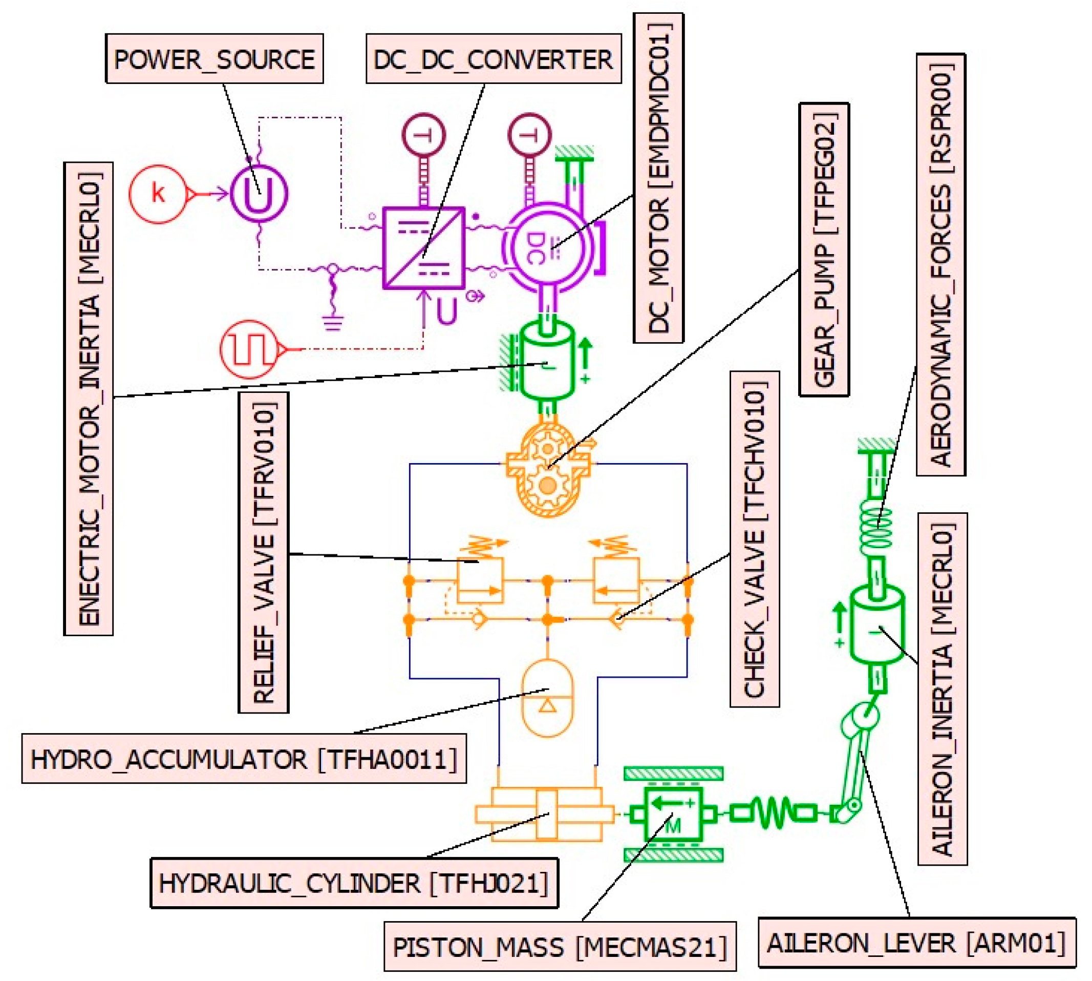
The scheme of the studied electro-hydrostatic servo actuator is a simplified one, well known in the specialized literature, and is presented in Figure 1.

Figure 1.
Schematic of the proposed electro-hydrostatic servo actuator.
This system is equipped with an electric motor that drives a gear pump. The pump circulates fluid between the chambers of the hydraulic cylinder to operate the aileron. The system also includes check valves, safety valves, and a hydraulic accumulator, all designed to ensure the proper functioning of the servo actuator. The specific roles of these components are not detailed here, as they are well documented in the specialized literature [4,5,6,7,8]. This type of servo actuator was studied both from a structural perspective and in terms of its behavior under various stress conditions in [30,31]. The electric motor selected for this servo actuator is a DC motor powered by a differential voltage of ±270 V. The studied servo actuator was designed for operating the ailerons of a commercial airliner. The main parameters of the used components are presented in Table 1, Table 2, Table 3, Table 4, Table 5 and Table 6.

Table 1.
Main parameters of the electric motor.
Table 2.
Main parameters of the gear pump.
Table 3.
Main parameters of the hydraulic cylinder.
Table 4.
Main parameters of the check valve.
Table 5.
Main parameters of the relief valve.
Table 6.
Main parameters of the hydro-accumulator.
The components of the servo actuator were considered to be located in a compartment within the wing, as shown in Figure 2, with the aileron being operated via a lever connected to the rod of the servo actuator cylinder.
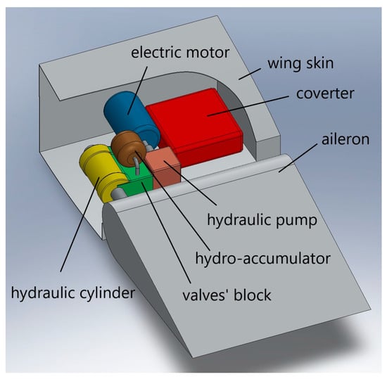
Figure 2.
Arrangement of servo actuator components in the wing compartment.
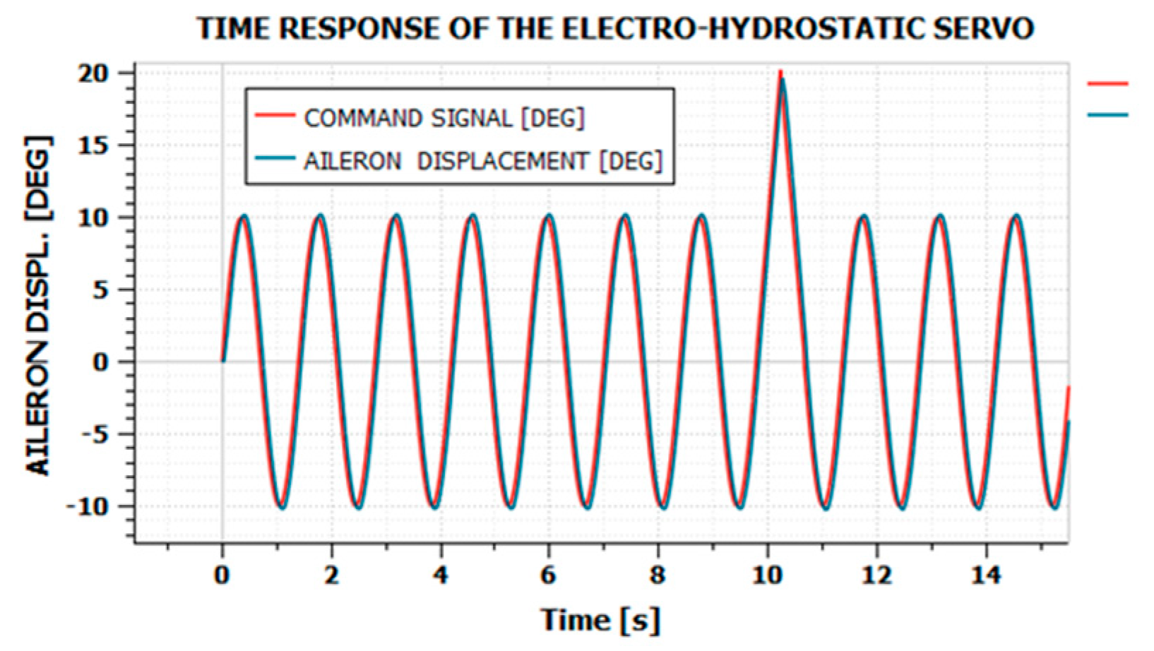
For the mechanical loading of the servo actuator, a sinusoidal signal with an amplitude of 10 degrees and a frequency of 0.72 Hz was considered. Additionally, every 10 s, a cycle at the maximum deflection speed of 45°/s is performed, with a maximum deflection of 20°. At an amplitude of 10 degrees and a frequency of 0.72 Hz, the maximum deflection speed of 45°/s, for which the servo actuator was designed, is reached. The aerodynamic forces were modeled using a torsion spring with a stiffness constant of 153 Nm/°. This stiffness constant was estimated for flight at the aircraft’s maximum speed. This load spectrum is specified in the specialized literature for testing the behavior of aviation servo actuators over long operating durations, aimed at sizing onboard hydraulic sources (pumps and hydraulic accumulators) and experimentally determining the operational lifespan of these servo actuators [1]. While it is not a real load spectrum, it provides a fairly accurate representation of the stresses a servo actuator for an airliner’s ailerons might experience during a more demanding flight—for instance, in turbulent atmospheric conditions or during more frequent maneuvers.
The tuning of the PID controllers used in the servo actuator system was carried out through numerical simulations in Siemens Simcenter Amesim to meet the performance specifications required for airliner servo actuators. These specifications include a maximum deflection speed of 45°/s and a maximum positioning error of 1° in the case of a ramp input signal with the maximum deflection speed. Additionally, the tuning process aimed to achieve operation that places minimal stress on the electric motor driving the pump. This electro-hydrostatic servo actuator configuration is particularly disadvantageous for the electric motor, which is subjected to very challenging operating conditions, including rapid speed variations and frequent direction changes. During the numerical simulations, it was observed that certain PID controller settings could ensure good mechanical performance of the servo actuator. However, the current drawn by the motor exhibited oscillations with amplitudes on the order of 20 A and frequencies on the order of tens of Hz. Under such conditions, the motor experiences significantly increased electrical and thermal stress. The response of the studied servo actuator, with tuning adjustments that minimize stress for the specified load spectrum, is presented in Figure 3.
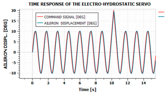
Figure 3.
The considered stress spectrum and the mechanical response to this stress.
3. Modeling the Operation of the Electro-Hydrostatic Servo Actuator
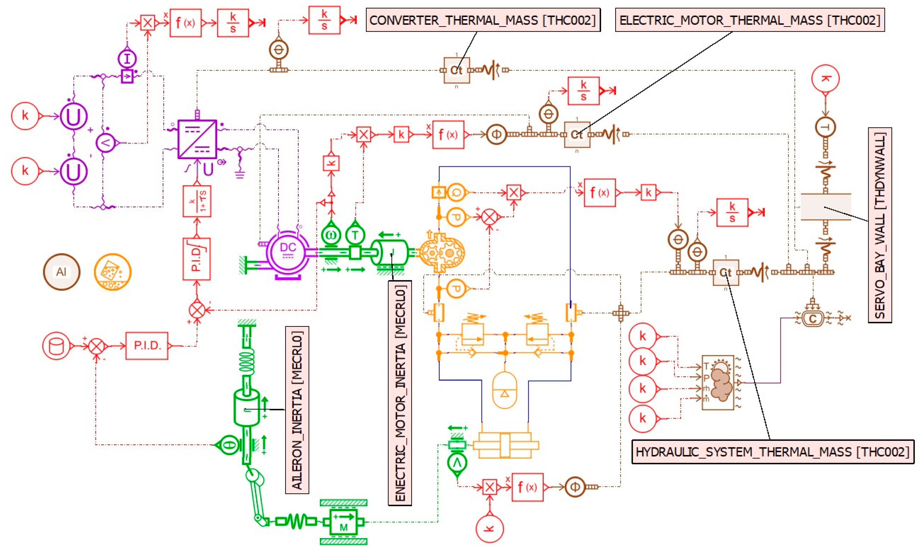
For modeling the operation of the considered electro-hydrostatic actuator, the Simcenter Amesim, Academic Bundle, version 2304, developed by Siemens, was used. This software enables the modeling of multiphysics systems and is well suited for studying the behavior of systems with interacting mechanical, electrical, hydraulic, thermal, and other components. The simulation scheme implemented in Amesim Academic Bundle is shown in Figure 4. The servo actuator was considered to be powered by a ±270 V differential voltage source via a controlled DC/DC converter. A predefined block in Amesim was used to simulate the overall functioning of the converter, taking its efficiency into account. Typically, converters used in such applications operate in switching mode [32]. The specialized literature mentions very high efficiencies for these converters. However, due to the demanding operating conditions of the electric motor, the converter also experiences significant stress, making it challenging to confirm whether such high efficiencies (around 95%) are indeed achievable. It is well known that in the complete design of electro-hydrostatic servo actuator systems, the design of the converter itself is a challenging aspect. In practice, these converters often generate significant heat. Nevertheless, for the simulations conducted in this study, a simplified block was used to model the converter’s operation, considering a predefined efficiency.
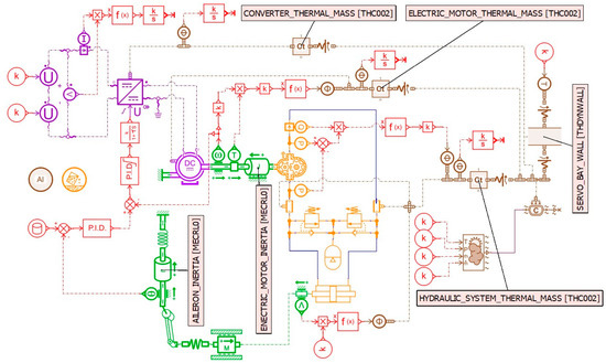
Figure 4.
Simulation scheme for the servo system in Simcenter Amesim.
The equations modeling the converter’s operation were taken into account as per references [32,33]:
The electric motor receives the voltage supplied by the converter and drives the pump to achieve the desired movement of the aileron. A DC motor was considered, for which a model is also implemented in Amesim. The equations that describe the operation of such a motor are provided in references [33,34,35]:
The model implemented in Amesim takes into account the heat generated through the Joule–Lenz effect but does not consider the frictional losses in the motor bearings. To model the heat generated by friction in the electric motor, the scheme includes a rotational speed and a torque transducer at the motor shaft, which are used to calculate the mechanical power output of the motor. The heat generated by the electric motor was calculated by considering a proportional relationship between the power at the output shaft and the heat generated by friction within the motor. The total heat generated in the electric motor was assumed to be the sum of the heat produced by the Joule–Lenz effect and that produced by friction.
A block implemented in the Thermal–Hydraulic set of Amesim was used to model the gear pump. This block considers the mechanical and hydraulic efficiency of the gear pump, but only to calculate thermal processes related to the hydraulic fluid (the variation in the hydraulic fluid’s enthalpy as it passes through the pump). However, it does not consider the heat transfer that occurs between the hydraulic fluid and the pump body, nor the heat generated by friction during pump operation. The main equations describing the operation of the gear pump under these conditions are as follows [33,36]:
To model the heat transfer between the hydraulic fluid and the pump body, as well as the hydraulic cylinder, two pipe segments with thermal transfer and viscosity were considered. It was assumed that the heat transfer from the hydraulic fluid to the pump and hydraulic cylinder is supplemented by the heat transfer produced through these two segments.
To model the heat generated by friction in the pump, two pressure transducers and a flow transducer were used, which allowed us to calculate the hydraulic power supplied by the pump:
and furthermore, it was assumed that the heat generated by friction in the pump was proportional to the hydraulic power supplied by the pump:
To model the hydraulic cylinder, a block from the Thermal–Hydraulic set of Amesim was used, as mentioned in references [33,36]. As in the case of the pump, this block takes into account the variations in the enthalpy of the fluid as it circulates through the hydraulic cylinder and performs mechanical work, but it does not consider the heat transfer between the hydraulic fluid and the cylinder body. The heat transfer between the fluid and the cylinder body was considered to be included in the heat transfer produced through the two pipe segments.
To estimate the amount of heat generated by friction in the hydraulic cylinder, a speed transducer for the cylinder rod was used, and the friction force between the sealing rings and the cylinder housing, as well as between the piston rod and the cylinder, was assumed to be constant. The heat generated by friction in the hydraulic cylinder was calculated in the form:
The equations describing the behavior of the hydraulic cylinder implemented in the block used were as follows [33,36]:
In the simulation scheme, there is also a lever that acts as the rotational inertia, which models the aileron. As in any mechanical system, there are friction moments at the aileron joint. However, these are very small compared to the friction in the pump or hydraulic cylinder, so their effect was neglected.
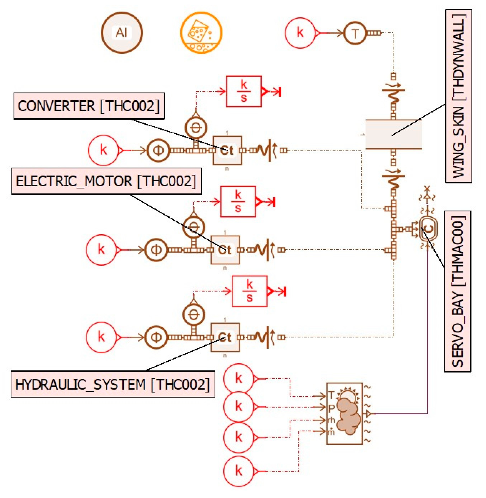
For modeling the thermal processes occurring in the operation of the considered electro-hydrostatic servo actuator, both the converter and the electric motor were modeled using thermal masses [33,37,38,39]. Each of these thermal masses receives the heat generated by its respective component and transfers the heat via convection within the compartment where the servo actuator is located. The total heat received by each of these thermal masses is calculated separately by integrating the thermal power received, allowing a global evaluation of the servo actuator’s efficiency.
The pump and hydraulic cylinder were considered thermally together as a single thermal mass. The hydraulic fluid transfers heat between them, ensuring temperature uniformity. Additionally, in some design variants, the hydraulic cylinder, valve block, and pump form a single unit to create a more compact configuration. This assembly of the pump, valve block, and hydraulic cylinder will be referred to as the hydraulic system in the following text.
For the hydraulic system, thermal modeling was performed in the form of a thermal mass that receives the heat generated in the pump and hydraulic cylinder and transfers it to the air mass in the servo actuator compartment via convection. The air mass in the servo compartment absorbs the heat from the components of the servo and transfers it to the exterior through the compartment wall, which is essentially the wing’s outer skin in that area. The heat transfer between the air in the servo compartment and the wing’s skin, as well as between the skin and the exterior, also occurs via convection. Given the thin thickness of the skin (about 1–3 mm), the heat conduction process through the wall can be neglected. Only the heat accumulation, which leads to an increase in the temperature of the wall, is considered.
The modeling of thermal processes associated with thermal masses is performed using the equation [33,37,38,39]:
and the convection processes:
The main parameters used for heat transfer processes are specified in Table 7:
Table 7.
The main parameters for heat exchange in the system components.
4. Studied Cases and Obtained Results
4.1. New Servo Actuator in Very Good Condition
The first case studied was that of a new servo actuator, where all components had optimal operating parameters. For this situation, the parameters from Table 8 were considered.
Table 8.
Parameter values used for simulation in case 4.1.
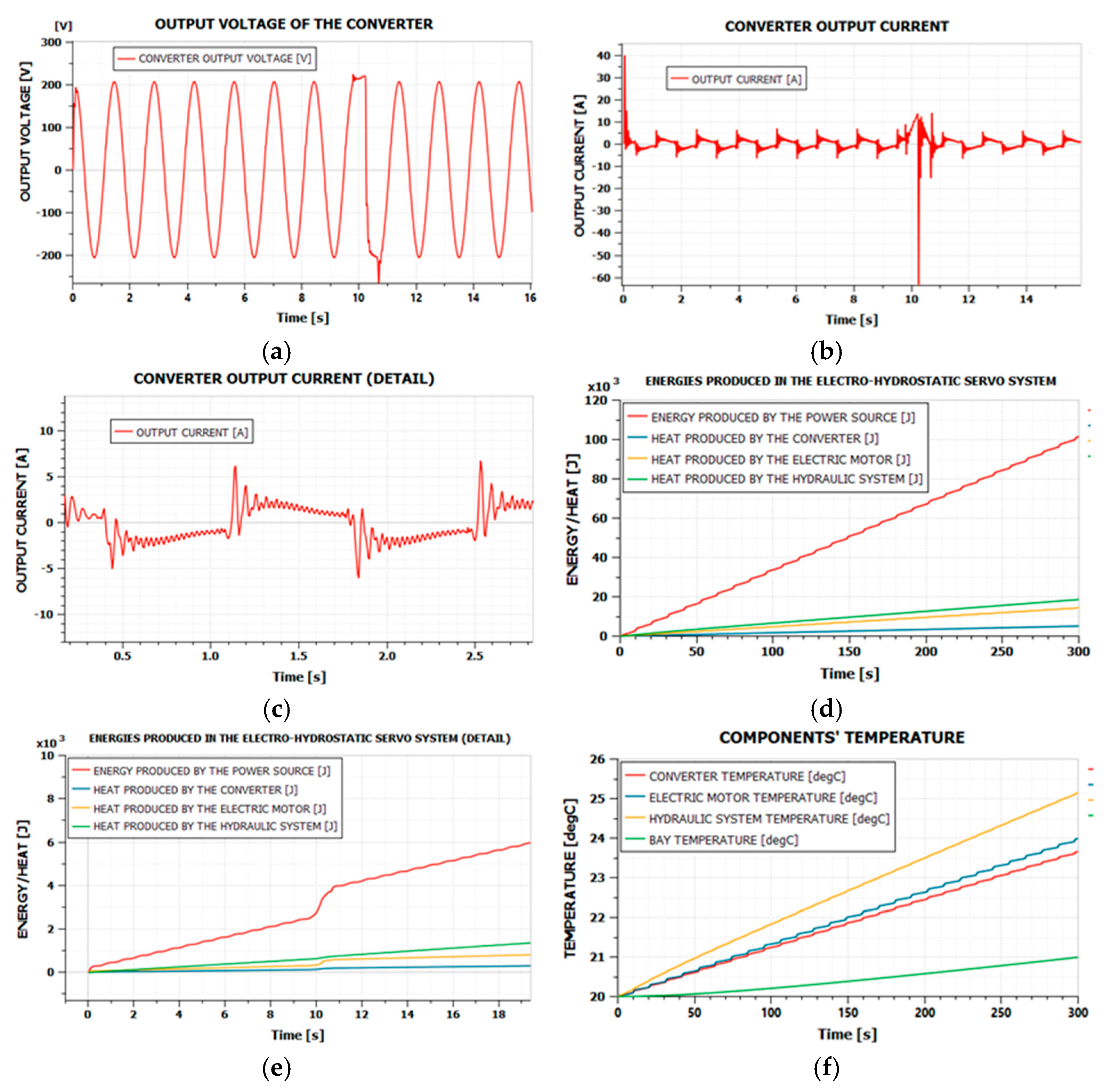
The aircraft was assumed to be on the ground, with the servo compartment completely sealed, without any mass transfer with the outside. Additionally, it was assumed that the air was circulated both inside and outside the compartment only by heating processes, so the air speeds were considered to be 0.3 m/s inside the compartment and 0.1 m/s outside of it. The results obtained through simulation are presented in Figure 5.
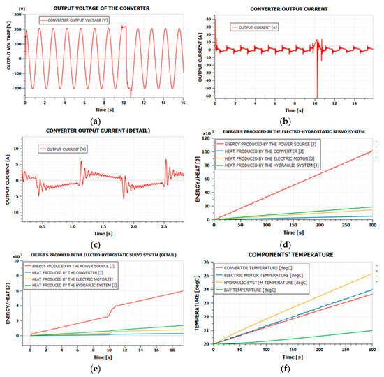
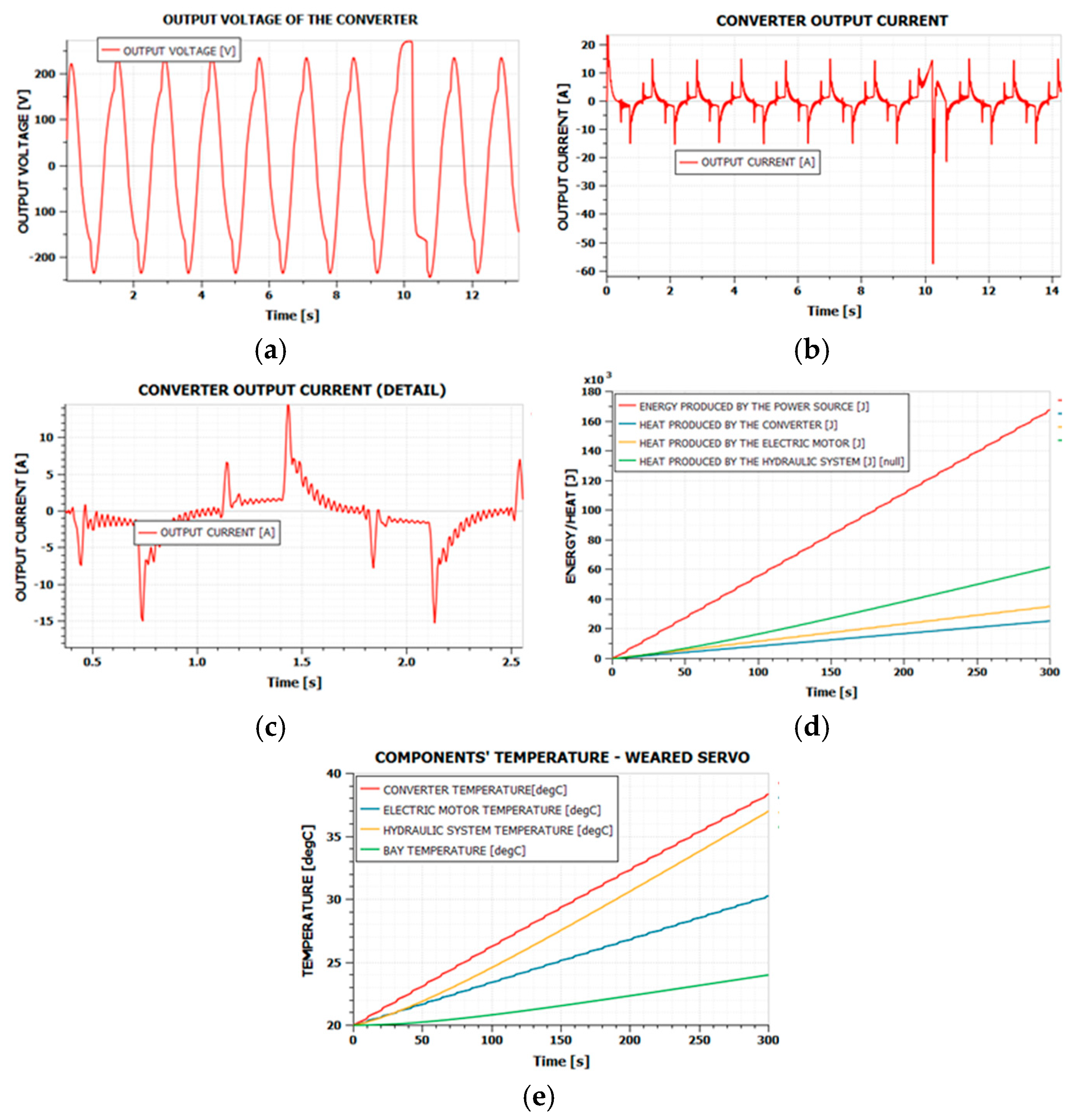
Figure 5.
Simulation results in case 4.1. (a) converter output voltage; (b) converter output current; (c) converter output current (detail); (d) energies produced in the system; (e) energies produced in the system (detail); (f) temperatures of the system components.
The variation in voltage and current produced by the converter is first presented in Figure 5a,b, respectively, while Figure 5c shows details of the current variation. A smooth variation in the voltage is observed, and the current exhibits minimal ripple, thus reducing both the electrical and thermal stress on the motor. From a thermal perspective, Figure 5d illustrates the variation in heat generated by the system’s components over the 300 s of operation, as well as the energy produced by the power supply. Figure 5e shows a detailed variation in the energies produced in the system, and Figure 5f presents the temperature variation in the system’s components. After 300 s, a slight temperature variation is noted in these components, indicating that the operation of the servo actuator does not pose significant thermal issues in this case.
The average servo actuator efficiency can be estimated using the formula:
Table 9.
Energy and heat values after 300 s in case 4.1.
The average efficiency obtained for the entire system of the servo actuator can be considered good. A verification of the efficiency can also be made by using the ratio between the power produced by the source and the power provided by the hydraulic cylinder. As mentioned earlier, the friction produced in the aileron articulation is negligible compared to the other energy losses. The force at the cylinder rod and the speed of the hydraulic cylinder’s movement were measured, the output power is computed as their product and then compared to the power produced by the electric power source at that moment. These estimates were made at a point close to the maximum stroke of the servo actuator, when the aileron had the maximum displacement speed, and the maximum moment was produced at the aileron hinge. The same calculation was performed for a point near the zero-crossing of the aileron, when the hinge moment was reduced. The resulting values are presented in Table 10.
Table 10.
Evaluation of the system’s efficiency using the ratio between the electric power source and the power at the hydraulic cylinder rod.
From Table 10, a significant variation in the instantaneous efficiency of the system is observed, which can be explained by the very different contributions of the friction forces in the hydraulic cylinder and pump compared to the force exerted on the hydraulic cylinder rod at a given moment. Additionally, such a calculation is not very significant because mechanical energy is redistributed over time among the system components, with part of the accumulated kinetic energy contributing to the continued movement of the aileron.
4.2. Worn Servo Actuator, Aircraft in Flight at 60 m/s, Closed Compartiment
The second case studied is that of a worn servo actuator, where the efficiencies have been degraded due to increased friction and losses in the hydraulic circuit, as well as a reduction in the efficiency of the converter. The scenario considered involves an aircraft in flight at a speed of 60 m/s, resulting in enhanced thermal transfer with the exterior of the compartment. The parameters considered in this case are presented in Table 11.
Table 11.
System parameters considered in case 4.2.
The simulation was performed for 300 s, assuming that all components initially started at a temperature of 20 °C. The results are presented in Figure 6.
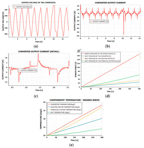
Figure 6.
Simulation results in case 4.2. (a) converter output voltage; (b) converter output current; (c) converter output current (detail); (d) energies produced in the system; (e) temperatures of the system components.
By first analyzing the voltage and current, it is observed that the command voltage variation remains sufficiently smooth. As for the current absorbed by the motor, the ripple increases, but not excessively. Additionally, the current peaks also increase, indicating that the motor is more stressed in this case. We can say that the behavior of the voltage and current is still sufficiently good in this case.
A global efficiency evaluation of the system can also be performed in this case, just as performed in Section 4.1, using Equation (33). The results for this case are presented in Table 12.
Table 12.
Energy and heat values after 300 s in case 4.2.
From Figure 6, it can be observed that the heating of the servo actuator occurs much more rapidly. The converter reaches a temperature of 38 °C within 300 s. For this reason, the simulation was repeated for a longer time interval of 1800 s, both for a well-maintained servo actuator and for a worn one. The comparative results are presented in Figure 7.
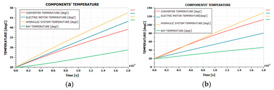
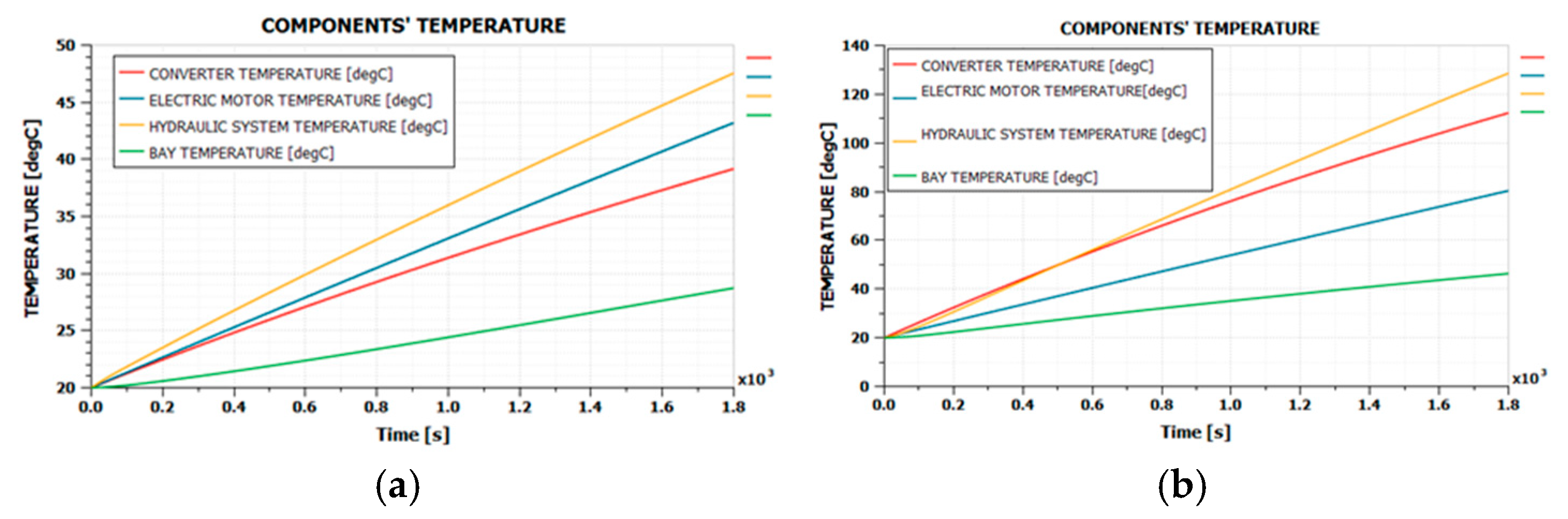
Figure 7.
The simulation results for an 1800 s flight at 20 °C as follows: (a) servo in good condition; (b) worn servo.
It is observed that within this 1800 s interval, for the servo in good condition, the components reach temperatures around 40–50 °C. However, for the worn servo, temperatures range between 80 and 130 °C. In the case of the worn servo, it is clear that a cooling system is required to reduce the temperature of the components. For the servo in good working condition, although the temperatures do not reach excessively high values, it is noted that they do not show a tendency to stabilize. As a result, it is expected that for longer-duration flights, even the servo in good condition will reach high temperatures. Therefore, a cooling system is necessary for this case as well, although not as urgently as for the worn servo.
4.3. Worn Servo Actuator with Bay Air Convection Cooling
Considering that the wing’s outer shell is very thin, we first tested a cooling possibility by increasing the air circulation speed inside the compartment, so that heat transfer between the system components and the wing’s outer shell would be more efficient. However, to accelerate the simulations, we created a simplified diagram, focusing only on the thermal part of the system. From Figure 5 and Figure 6, we determined the average heat generated per unit of time for each component of the system and then, in the simplified diagram, replaced the actual components with heat sources that have the same power as the real components. The values of the average heat generated per unit of time for each component, obtained from Figure 5 and Figure 6, are presented in Table 13.
Table 13.
Heat outputs obtained for the system components.
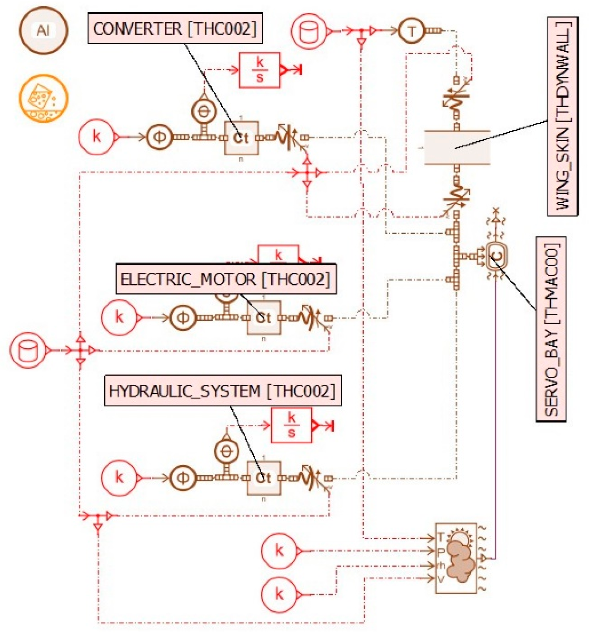
The simplified simulation diagram is presented in Figure 8.

Figure 8.
The simplified diagram for simulating the thermal behavior of the servo actuator.
The variation in temperature for the components of the system, for different air circulation speeds inside the servo compartment, is presented in Figure 9. The same situation was considered, with all components starting from an initial temperature of 20 °C.
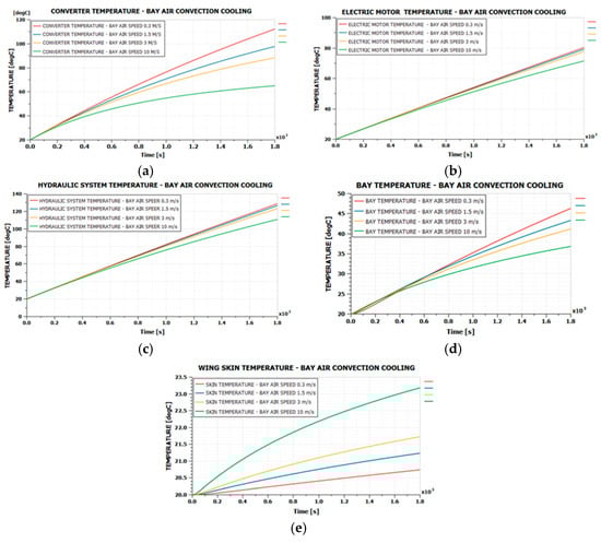
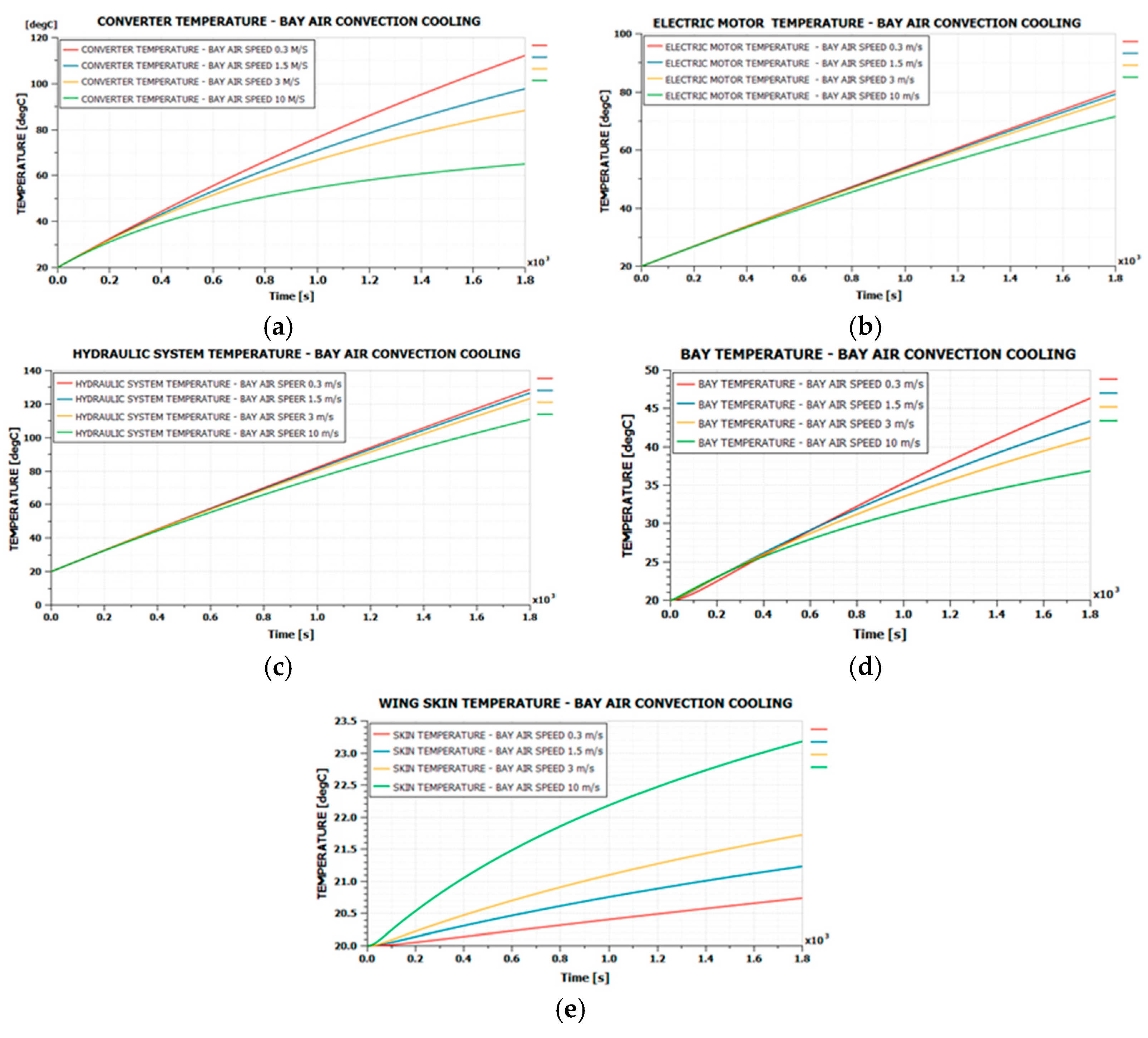
Figure 9.
The case with cooling through air recirculation within the compartment. (a) converter temperature; (b) electric motor temperature; (c) hydraulic system temperature; (d) bay temperature; (e) wing skin temperature.
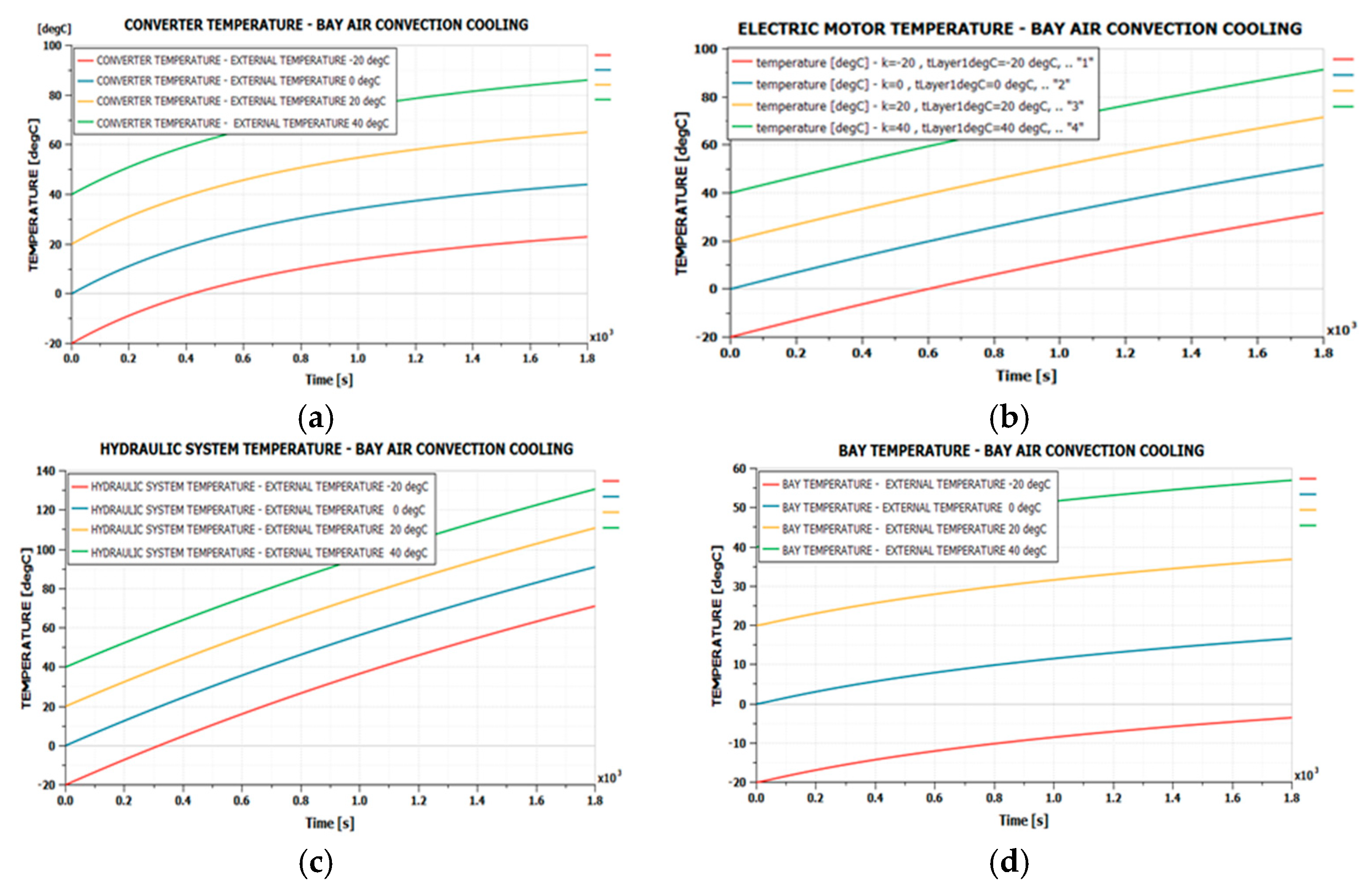
It can be observed from Figure 9 that the efficiency of this cooling method is not very high. It significantly reduces the temperature of the converter, for an air recirculation speed of 10 m/s, but the effects on the motor and hydraulic system are limited. However, we also studied the effects of this method for an air recirculation speed of 10 m/s, but starting from different initial temperatures of the components. The initial temperatures were considered to be −20, 0, 20, and 40 °C. The results are presented in Figure 10. It is observed that, in the case of the hydraulic system, even with external temperatures as low as −20 °C, temperatures of 70 °C are reached, without a pronounced tendency for the temperature to stabilize.
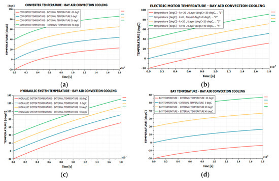
Figure 10.
The case of cooling with air recirculation from the compartment, starting from different initial temperatures. (a) converter temperature; (b) electric motor temperature; (c) hydraulic system temperature; (d) bay temperature.
4.4. Worn Servo Actuator with External Air Cooling
A commonly used solution for cooling equipment on aircraft is the use of external air taken through air intakes and directed into the compartments where the equipment is located. Since the first option did not yield satisfactory results, we are testing this alternative, considering an air intake with an opening of 20 × 10 cm through which the air is taken at a speed equal to the aircraft’s flight speed. This time, convection occurs with air at the aircraft’s flight speed, with a flow rate determined by the flight speed and the size of the air intake, and at a temperature equal to the outside temperature. We assume the aircraft’s external temperature, although strictly speaking, the stagnation temperature of the airflow, or an intermediate temperature between the external temperature and the stagnation temperature, should be considered. The simulation model has been adapted, resulting in the diagram shown in Figure 11.

Figure 11.
External air cooling.
Three variants were tested for this case: a constant external temperature of 40 °C with different flight speeds, a constant flight speed with different external temperatures, and a predefined variation in speed and temperature similar to that of a flight lasting approximately one hour. The results are presented in Figure 12, Figure 13 and Figure 14.
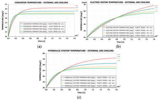
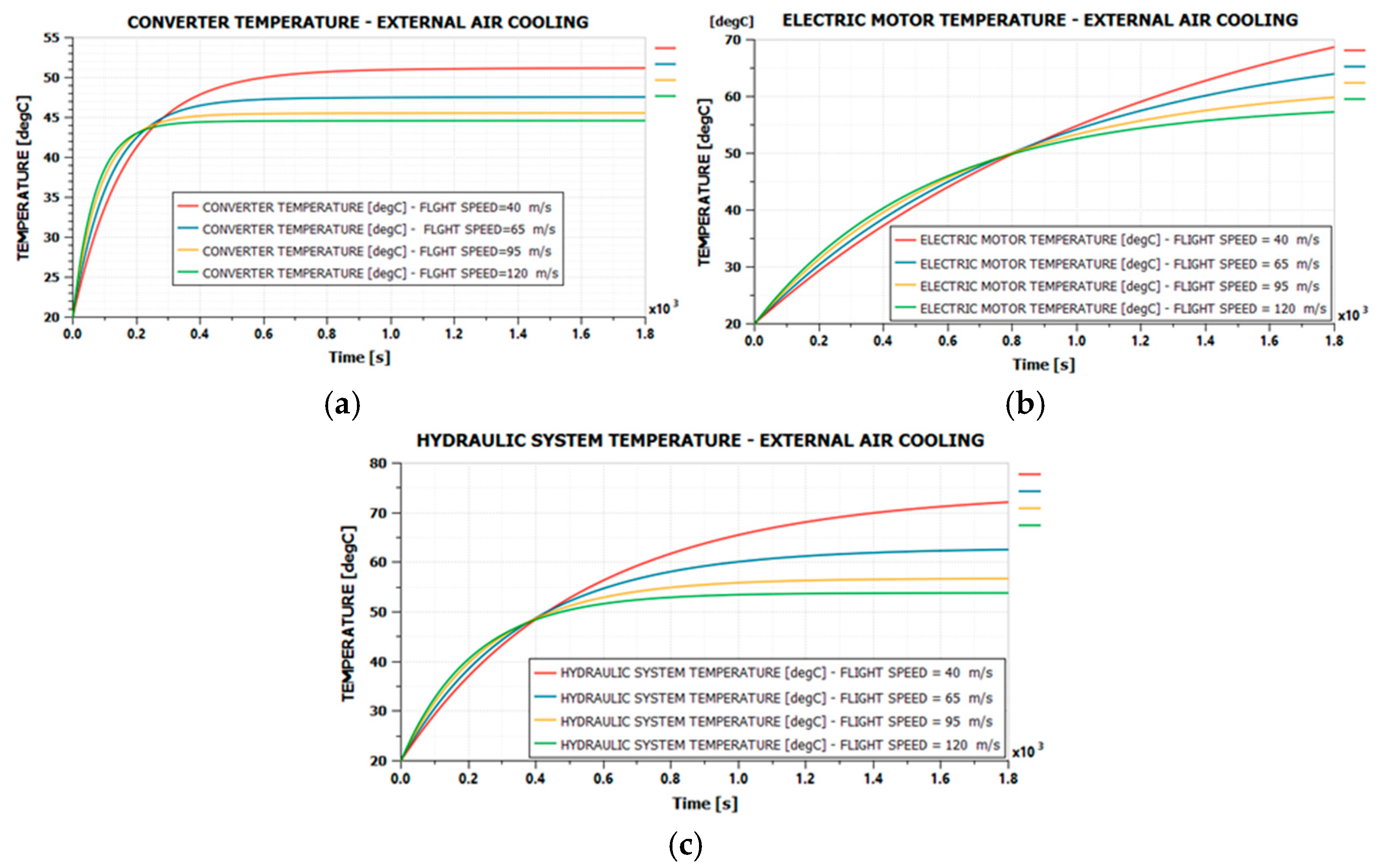
Figure 12.
External air cooling at 40 °C and different flight speeds. (a) converter temperature; (b) electric motor temperature; (c) hydraulic system temperature.
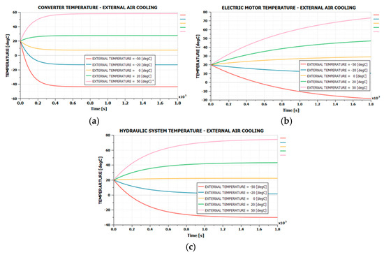
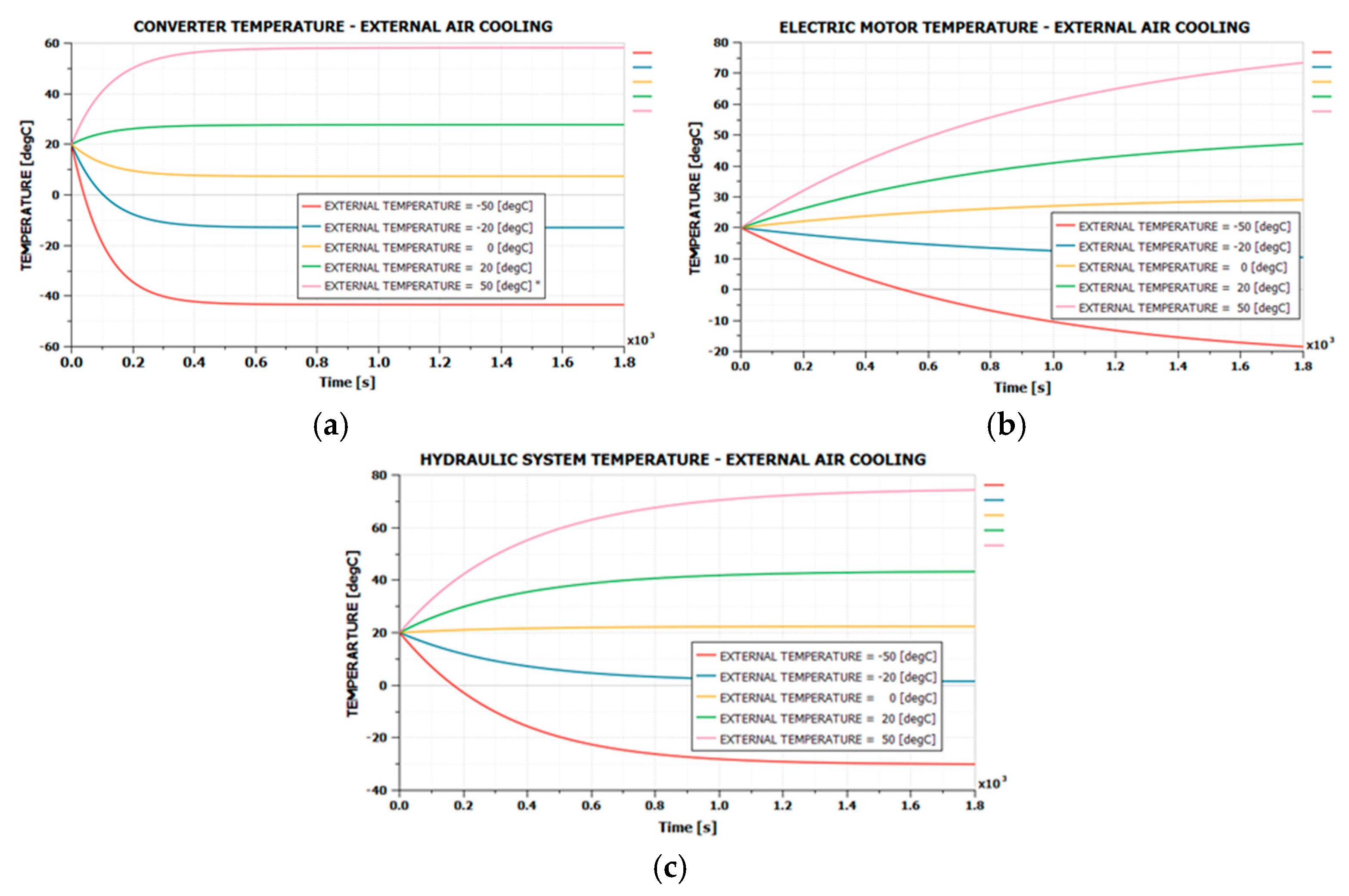
Figure 13.
External air cooling at 60 m/s and different external temperatures. (a) converter temperature; (b) electric motor temperature; (c) hydraulic system temperature.
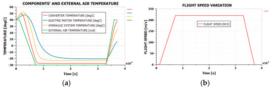
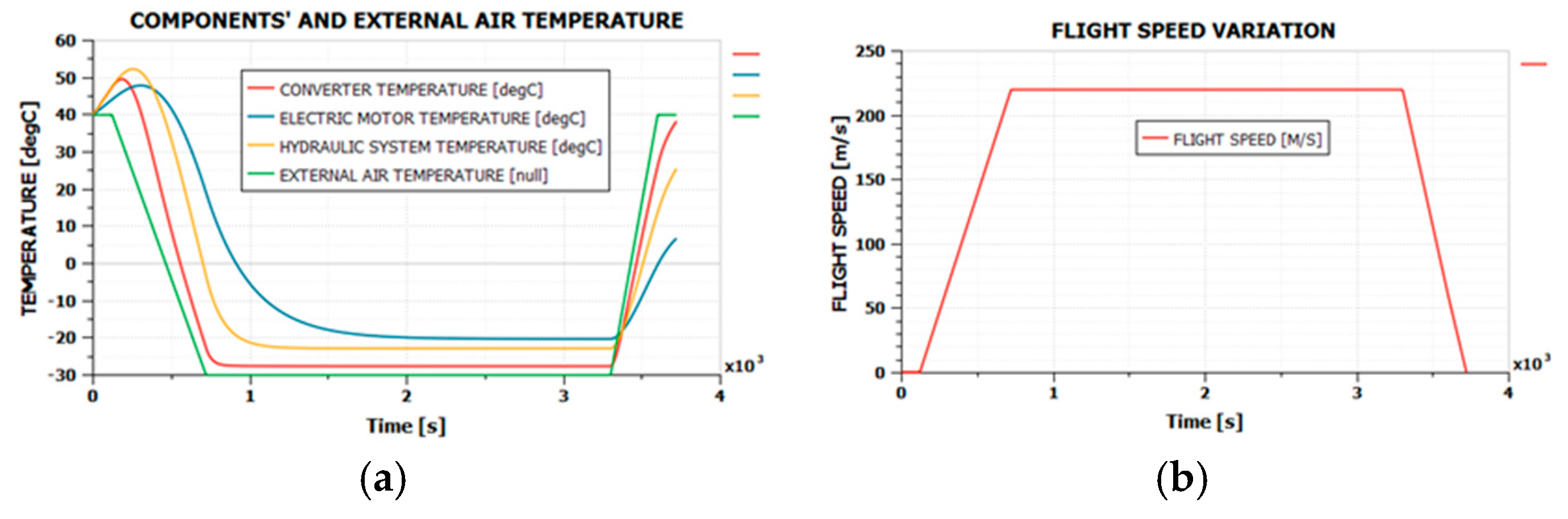
Figure 14.
External air cooling on a flight with variable speed and external temperature, worn servo actuator. (a) temperatures of the system components; (b) flight speed variation.
The variation of the external temperature is represented in green in Figure 14a and Figure 15a, while the variation in the flight speed is shown in Figure 14b and Figure 15b. The simulation assumes a ground phase with constant temperature and zero speed for 300 s, followed by takeoff and climb, during which the temperature decreases from 40 °C to −30 °C, and the speed increases from 0 to 220 m/s. This is followed by a cruise phase with constant speed and temperature, then a descent with a reduction in speed and a return of the temperature to its initial value, and finally, a taxiing phase on the ground until the speed reaches zero.
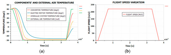
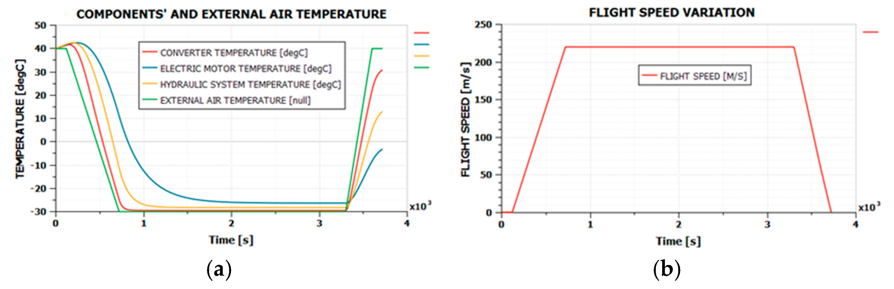
Figure 15.
External air cooling on a flight with variable speed and external temperature, servo actuator in a good condition. (a) temperatures of the system components; (b) flight speed variation.
It is observed that this solution effectively limits the temperatures of the components when the external temperature is high. However, when the temperature is low, the components reach a temperature close to the external one during cruise mode. In these situations, other issues may arise regarding the operation of the servo actuator, related to the contraction of various structural elements of the motor and pump, the significant decrease in the temperature of the sealing seals, and other problems that cannot be studied with the mathematical models used in this work. It is well known that the operation of aircraft servo actuators at low temperatures has caused significant problems over time. It is necessary either for the system’s components to be specially designed and tested for operation at such low temperatures, or for temperature control systems to be used. One solution is to adjust the air intake opening of the servo compartment depending on flight speed, servo temperature, and external temperature. However, this solution is not efficient when the aircraft takes off from runways already at low external temperatures. For such situations, it would be necessary to regulate the temperature using warm air taken from the engine. Such studies are intended to be conducted in a future paper.
5. Conclusions
Different situations have been studied regarding the behavior of an electro-hydrostatic servo actuator in terms of temperatures reached in operation, for different flight situations. The first conclusion that can be drawn is that a servo actuator in very good operating conditions does not need cooling. The heat transfer by convection, between the components and the air in the compartment, between the air in the compartment and the wing skin, and then between the wing skin and the external environment, is sufficient. In this situation, an enclosed compartment is sufficient for ensuring that the actuator operating conditions are maintained within acceptable limits for component temperature.
As the components of the servo actuator begin to wear, issues related to overheating start to arise. In the studies conducted, a significant degradation of the components’ qualities was considered, which can be prevented through regular maintenance of the servo actuator. However, the wear of components inevitably leads to an increase in energy losses in the form of heat from the servo actuator components. As highlighted in these studies, wear can lead to significant heat losses, which, in turn, result in the overheating of the servo actuator components if the servo actuator is installed in a closed compartment without external cooling options. Cooling with air taken from the exterior of the aircraft is a solution as long as the servo actuator can operate at low temperatures. However, if the components experience problems operating at low temperatures, around −30 °C or even lower, a temperature regulation system is necessary, either by adjusting the air intake valve opening or by using a flow of warm air taken from the engine.
The use of temperature control systems for servo actuators offers a way to ensure the thermal regime of the servo actuator. However, considering that flight control actuators are of vital importance onboard an aircraft, this is not a desirable solution. Failure of the servo actuator temperature control systems can lead to the servo actuator operating outside its permissible temperature range and, consequently, to a possible failure of the respective flight control. An acceptable compromise would be to use air cooling systems that take in air from the outside, combined with the use of servo actuators whose components can function correctly at low temperatures, preferably down to −60 °C in the case of commercial aircraft, to ensure their access to any geographical area.
Results obtained in this work are close to other results presented in the literature. Different precision levels have been adopted in other authors’ works, and the results are consistent with the external and load conditions. In [29], numerical simulations were presented, and experimental results were obtained for the thermal behavior of an EHA. In [40], numerical simulations were performed with results comparable with the present work. In [26,41], numerical simulations confirmed by experimental results are presented, using mathematical models of different precision levels. The method presented in this work has the advantage of a balance between the complexity of the mathematical model and the precision of the obtained results. With a relatively small effort, realistic results were obtained.
The simulations conducted also allowed for an evaluation of the overall efficiency of the servo actuator system. The evaluations based on instantaneous powers (the instantaneous power generated by the energy source and the instantaneous power produced at the hydraulic cylinder rod) can be considered inconclusive due to the redistribution of mechanical energy between the hydraulic cylinder and the aileron during operation. However, the evaluation based on the energy produced by the energy source and the heat dissipated within the system led to credible values for such a system. An efficiency value of approximately 60% was obtained for a well-functioning system, but this efficiency deteriorated, potentially reaching around 28% for a used servo actuator. Given that the efficiency of classic electrohydraulic servo actuators is primarily limited by the servo valve at a value of 67%, and then further affected by other energy losses within the system, it can be said that the overall efficiency of the electro-hydrostatic servo actuator system is very high.
Author Contributions
Conceptualization, L.D. and T.L.G.; methodology, L.D. and J.-I.C.; software, J.-I.C. and A.-A.C.; validation L.D. and T.L.G.; formal analysis, L.D. and J.-I.C.; investigation, L.D., J.-I.C. and B.V.; resources, B.V.; data curation, L.D, T.L.G. and J.-I.C.; writing—original draft preparation, A.-A.C.; writing—review and editing, A.-A.C.; visualization, J.-I.C. and B.V.; supervision, L.D.; project administration, J.-I.C. All authors have read and agreed to the published version of the manuscript.
Funding
This research received no external funding.
Data Availability Statement
The data presented in this study are available on request from the corresponding author due to privacy.
Conflicts of Interest
The authors declare no conflicts of interest.
Abbreviations
| Ku | voltage gain factor of the converter |
| Uout, Uin | converter output (input) voltage |
| Iin, Iout | converter input (ouput) current |
| heat power generated by the converter | |
| converter efficiency | |
| Pout, Pin | converter output (input) power |
| Kt | torque constant of the motor |
| ω | motor (pump) angular speed |
| Ia | motor current |
| Ua | motor feeding voltage |
| Ra | motor winding resistance |
| La | motor winding inductance |
| Γ | motor torque |
| hmot | heat generated by the Joule–Lenz effect in the motor |
| qth | gear pump theoretical flow |
| displ | pump displacement |
| torqueth | pump theoretical driving torque |
| pout, pin | pump output (input) pressure |
| gear pump real flow | |
| gear pump volumetric efficiency | |
| torquereal | gear pump real driving torque |
| gear pump hydro-mechanical efficiency | |
| dmout | gear pump masic flow |
| hydraulic liquid density | |
| hout, hin | specific enthalpy of the output (input) flow |
| Phyd | hydraulic power of the gear pump |
| heat power generated by the pump | |
| heat power generated by the hydraulic cylinder friction | |
| Frod | force to the cylinder rod |
| p1, p2 | pressures in the hydraulic cylinder chambers |
| A1, A2 | piston effective areas |
| hydraulic cylinder viscous friction coefficient | |
| qleak | hydraulic cylinder leakage flow |
| kleak | hydraulic cylinder leakage constant |
| m1, m2 | hydraulic liquid mass in the cylinder’s chambers |
| H1, H2 | enthalpy of the hydraulic liquid in the cylinder’s chambers |
| T1, T2 | hydraulic liquid temperatures in the cylinder’s chambers |
| isobar dilatation coefficient of the hydraulic liquid | |
| isotherm compressibility coefficient of the hydraulic liquid |
References
- Dinca, L. Echipamente si Sisteme Hidropneumatice de Bord; Universitaria Publishing: Craiova, Romania, 2008. [Google Scholar]
- 524 Killed in Worst Single Air Disaster. Available online: https://www.theguardian.com/fromthearchive/story/0,,1017027,00.html (accessed on 10 December 2024).
- United Airlines Flight 232 Crash: July 19, 1989, in Sioux City, Iowa. Available online: https://www.cliffordlaw.com/united-airlines-flight-232-crash-july-19-1989-in-sioux-city-iowa/ (accessed on 15 December 2024).
- Larson, F. Evaluation of Aircraft Actuator Technologies. Master’s Thesis, Linkoping University, Linköping, Sweden, 2023. [Google Scholar]
- Alle, N.; Hiremath, S.; Makaram, S.; Subramanian, K.; Talukdar, A. Review on electro hydrostatic actuator for flight control. Int. J. Fluid Power 2016, 17, 125–145. [Google Scholar] [CrossRef]
- Mare, J.C.; Fu, J. Review on signal-by-wire and power-by-wire actuation for more electric aircraft. Chin. J. Aeronaut. 2017, 30, 857–870. [Google Scholar] [CrossRef]
- Kumar, M. A survey on electro hydrostatic actuator: Architecture and way ahead. Mater. Today Proc. 2021, 45, 6057–6063. [Google Scholar] [CrossRef]
- Li, J.; Yu, Z.; Huang, Y.; Li, Z. A Review of electromechanical actuation system for more electric aircraft. In Proceedings of the International Conference on Aircraft Utility Systems, Beijing, China, 10–12 October 2016. [Google Scholar]
- Zhou, F.; Liu, H.; Zhang, P.; Ouyang, X.; Xu, L.; Ge, Y.; Yang, H. High-Precision Control Solution for Asymmetrical Electro-Hydrostatic Actuators Based on the Three-Port Pump and Disturbance Observers. IEEE/ASME Trans. Mechatron. 2023, 28, 396–406. [Google Scholar] [CrossRef]
- Chao, Q.; Zhang, J.; Xu, B.; Huang, H.; Pan, M. A Review of High-Speed Electro-Hydrostatic Actuator Pumps in Aerospace Applications: Challenges and Solutions. J. Mech. Des. 2019, 141, 050801. [Google Scholar] [CrossRef]
- Shang, Y.; Li, X.; Qian, H.; Wu, S.; Pan, Q.; Huang, L.; Jiao, Z. A Novel Electro Hydrostatic Actuator System with Energy Recovery Module for More Electric Aircraft. IEEE Trans. Ind. Electron. 2020, 67, 2991–2999. [Google Scholar] [CrossRef]
- Jiao, Z.; Li, Z.; Shang, Y.; Wu, S.; Song, Z.; Pan, Q. Active Load Sensitive Electro-Hydrostatic Actuator on More Electric Aircraft: Concept, Design, and Control. IEEE Trans. Ind. Electron. 2022, 69, 5030–5040. [Google Scholar] [CrossRef]
- Zhang, J.; Li, L.; Zhang, X.; Zhang, T.; Yuan, Y. Delay Analysis and the Control of Electro-Hydrostatic Actuators. Appl. Sci. 2022, 12, 3089. [Google Scholar] [CrossRef]
- Li, Z.; Shang, Y.; Jiao, Z.; Lin, Y.; Wu, S.; Li, X. Analysis of the dynamic performance of an electrohydrostatic actuator and improvement methods. Chin. J. Aeronaut. 2018, 31, 2312–2320. [Google Scholar] [CrossRef]
- Navatha, A.; Bellad, K.; Hiremath, S.; Karunanidhi, S. Dynamic Analysis of Electro Hydrostatic Actuation System. Global Colloquium in Recent Advancement and Effectual Researches in Engineering, Science and Technology (RAEREST 2016). Procedia Technol. 2016, 25, 1289–1296. [Google Scholar] [CrossRef]
- Yang, B.; Lu, Y.; Jiang, H.; Ling, Z.; Li, T.; Liu, H.; Ouyang, X. Quantitative Comparative Study on the Performance of a Valve-Controlled Actuator and Electro-Hydrostatic Actuator. Actuators 2024, 13, 118. [Google Scholar] [CrossRef]
- Igumnov, L.; Metrikin, V. On the effect of correcting the electro-hydraulic servo drive on the dynamic characteristics of the «servo rive-mass» system of an airplane. IFAC-Pap. OnLine 2015, 48, 640–644. [Google Scholar] [CrossRef]
- Fu, Y.; Hang, X.; Sepehri, N.; Zhou, G.; FU, J.; Yu, L.; Yang, R. Design and performance analysis of position-based impedance control for an electrohydrostatic actuation system. Chin. J. Aeronaut. 2018, 31, 584–596. [Google Scholar] [CrossRef]
- Wang, T.; Luo, G.; Chen, Z.; Tu, W.; Liu, C. An Improved Robust Model Predictive Speed Control With Inertia Identification for PMSM Drives in the Electrohydrostatic Actuator. IEEE Trans. Power Electron. 2023, 38, 13825–13841. [Google Scholar] [CrossRef]
- Wang, M.; Wang, Y.; Fu, Y.; Yang, R.; Zhao, J.; Fu, J. Experimental Investigation of an Electro-Hydrostatic Actuator Based on the Novel Active Compensation Method. IEEE Access 2020, 8, 170635–170649. [Google Scholar] [CrossRef]
- Efimov, D.; Cieslak, J.; Zolghadri, A.; Henry, D. Actuator fault detection in aircraft systems: Oscillatory failure case study. Annu. Rev. Control 2013, 37, 180–190. [Google Scholar] [CrossRef]
- Qi, H.; Zhao, D.; Liu, D.; Liu, X. Double Redundancy Electro-Hydrostatic Actuator Fault Diagnosis Method Based on Progressive Fault Diagnosis Method. Actuators 2022, 11, 264. [Google Scholar] [CrossRef]
- Wang, C.; Fan, I.-S.; King, S. Failures Mapping for Aircraft Electrical Actuation System Health Management. In Proceedings of the 7th European Conference of the Prognostics and Health Management Society, Turin, Italy, 6–8 July 2022; ISBN 978-1-936263-36-3. [Google Scholar]
- Sun, X.; Wang, X.; Zhou, Z.; Zhou, Z. Active Fault-Tolerant Control Strategy for More Electric Aircraft under Actuation System Failure. Actuators 2020, 9, 122. [Google Scholar] [CrossRef]
- Zhang, J.; Li, Y.; Xu, B.; Pan, M.; Chao, Q. Experimental study of an insert and its influence on churning losses in a high-speed electro-hydrostatic actuator pump of an aircraft. Chin. J. Aeronaut. 2019, 32, 2028–2036. [Google Scholar] [CrossRef]
- Jiao, Z.; Li, Y.; Yu, T.; Jiang, C.; Huang, L.; Shang, Y. Dynamic thermal coupling modeling and analysis of wet electro-hydrostatic actuator. Chin. J. Aeronaut. 2022, 35, 298–311. [Google Scholar] [CrossRef]
- Jiang, C.; Shang, Y.; Yu, T.; Liu, Z.; Li, M. Modeling and Analysis of Electro-Hydrostatic Actuators Efficiency. In Proceedings of 34th Congress of the International Council of Aeronautical Sciences, Florence, Italy, 9–13 September 2024. [Google Scholar]
- Li, Y.; Ji, Z.; Yang, L.; Zhang, P.; Xu, B.; Zhang, J. Thermal-fluid-structure coupling analysis for valve plate friction pair of axial piston pump in electrohydrostatic actuator (EHA) of aircraft. Appl. Math. Model. 2017, 47, 839–858. [Google Scholar] [CrossRef]
- Liu, J.; Huang, H.; Ge, Y.; Zhao, X.; Deng, W.; Gao, G.; Yao, J. Thermal Characteristic and Analysis of Electro-Hydrostatic Actuator. IEEE Access 2024, 12, 34222–34234. [Google Scholar] [CrossRef]
- Buhaianu, A.R.; Dinca, L.; Dumitrache, A.; Benec-Mincu, G.-M. Numerical Simulations of Some Characteristics of Electrohydrostatic Actuators Used in Aviation. Int. Conf. Numer. Anal. Appplied Math. 2024, 3094, 500057. [Google Scholar] [CrossRef]
- Dinca, L.; Bogateanu, R.; Corcau, J.I.; Dumitrache, A.; Suatean, B. Numerical Simulation for Redundant Electro-Hydrostatic Servo-Actuators under Certain Special Conditions. Energies 2022, 15, 5906. [Google Scholar] [CrossRef]
- Trzynadlowsky, A. Power Electronic Converters and Systems–Frontiers and Applications; IET Power and Energy Series 74; The Institution of Engineering and Technology: London, UK, 2016. [Google Scholar]
- Siemens Simcenter Academic Bundle User Manual. Available online: https://www.plm.automation.siemens.com/ (accessed on 1 December 2024).
- Krishnan, R. Electric Motor Drives–Modelling, Analysis and Control; Prentice Hall: Upper Saddle River, NJ, USA, 2001. [Google Scholar]
- Beaty, W.; Kirtley, J., Jr. Electric Motor Handbook; McGraw-Hill: New York, NY, USA, 2024. [Google Scholar]
- Vacca, A. Hydraulic Fluid Power: Fundamentals, Applications and Circuit Design; John Wiley and Sons Ltd.: Hong Kong, China, 2021. [Google Scholar]
- Cengel, Y.; Ghajar, A. Heat and Mass Transfer—Fundamentals and Applications; McGraw Hill: New York, NY, USA, 2015. [Google Scholar]
- Rosenow, W.; Hartnett, J.; Cho, Y. Handbook of Heat Transfer, 3rd ed.; McGraw Hill: New York, NY, USA, 1998. [Google Scholar]
- Rajput, R.K. Heat and Mass Transfer. S. Chand and Company LTD; S Chand: New Delhi, India, 2012. [Google Scholar]
- Li, K.; Lv, Z.; Lu, K.; Yu, P. Thermal-hydraulic Modeling and Simulation of the Hydraulic System Based on the Electro-Hydrostatic Actuator. Procedia Eng. 2014, 80, 272–281. [Google Scholar] [CrossRef]
- Nie, S.; Gao, J.; Ma, Z.; Yin, F.; Ji, H. An online data-driven approach for performance prediction of electro-hydrostatic actuator with thermal-hydraulic modeling. Reliab. Eng. Syst. Saf. 2023, 236, 109289. [Google Scholar] [CrossRef]

Disclaimer/Publisher’s Note: The statements, opinions and data contained in all publications are solely those of the individual author(s) and contributor(s) and not of MDPI and/or the editor(s). MDPI and/or the editor(s) disclaim responsibility for any injury to people or property resulting from any ideas, methods, instructions or products referred to in the content. |
© 2025 by the authors. Licensee MDPI, Basel, Switzerland. This article is an open access article distributed under the terms and conditions of the Creative Commons Attribution (CC BY) license (https://creativecommons.org/licenses/by/4.0/).