
Motion Analysis of Wire Rope Maintenance Device

Abstract
:1. Introduction
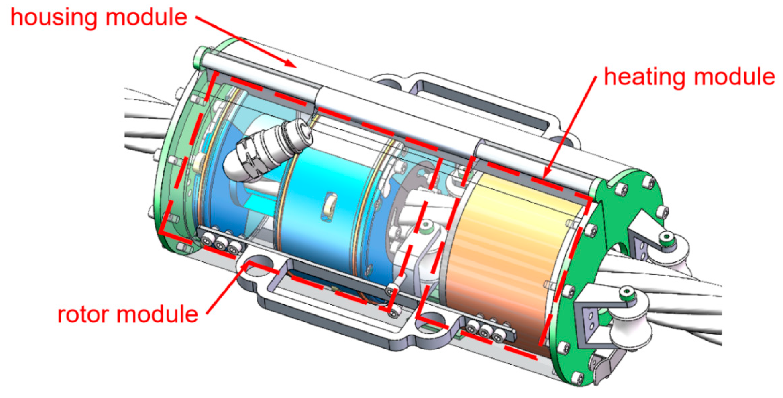
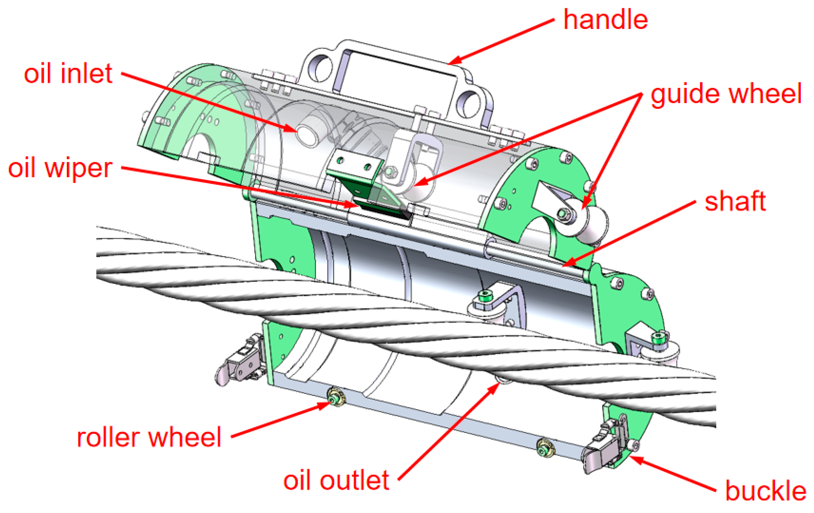
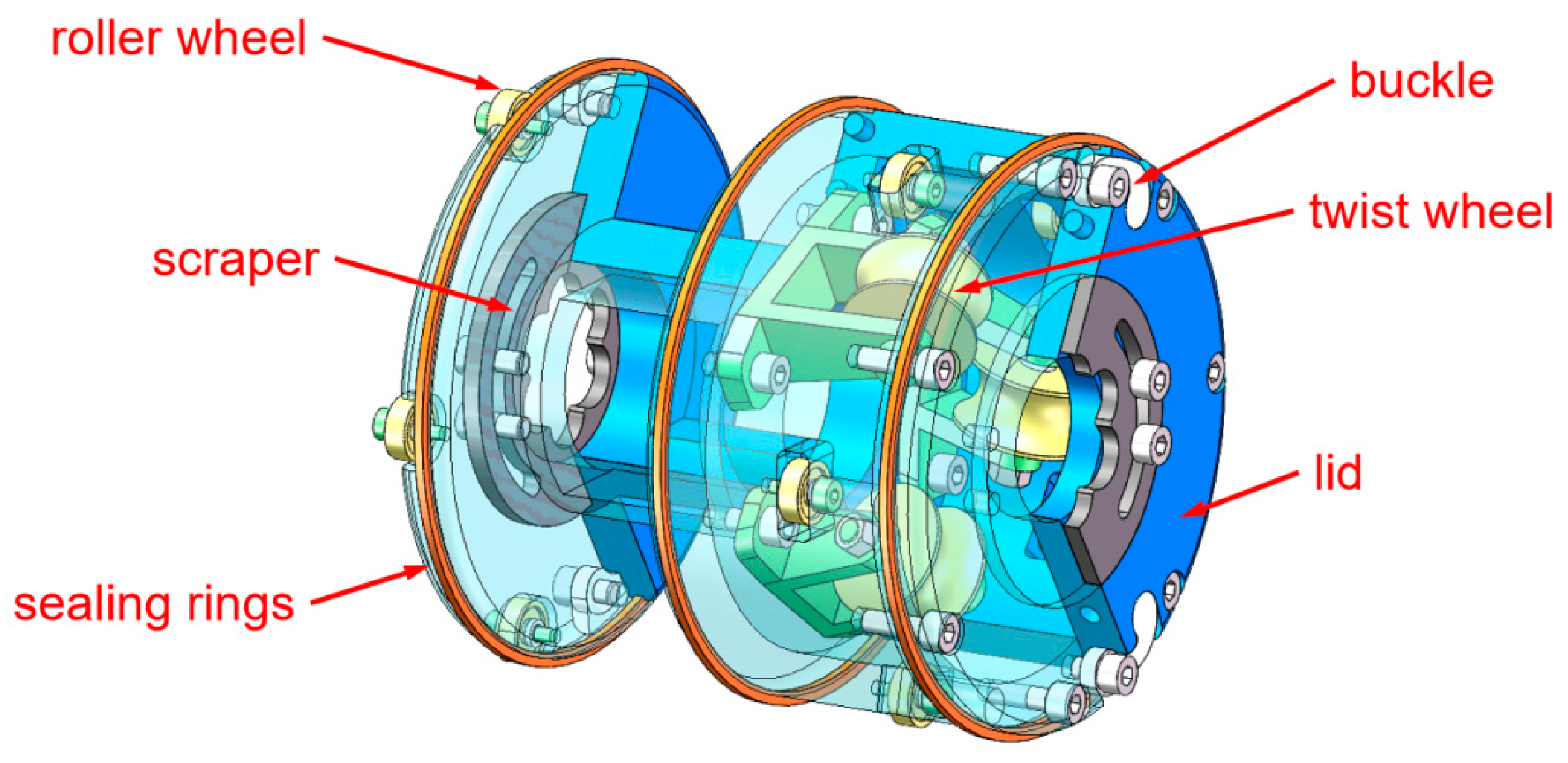
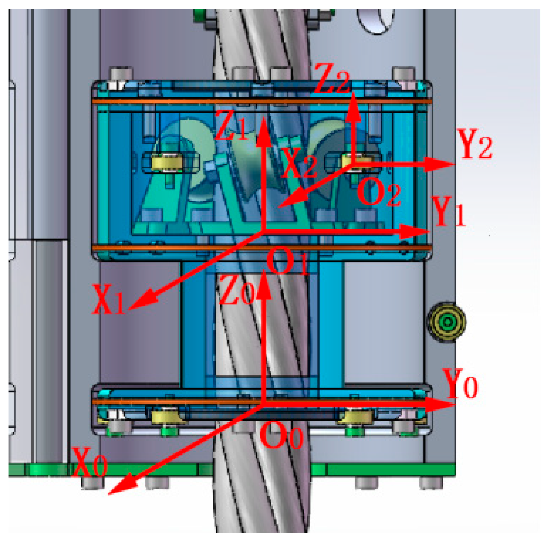
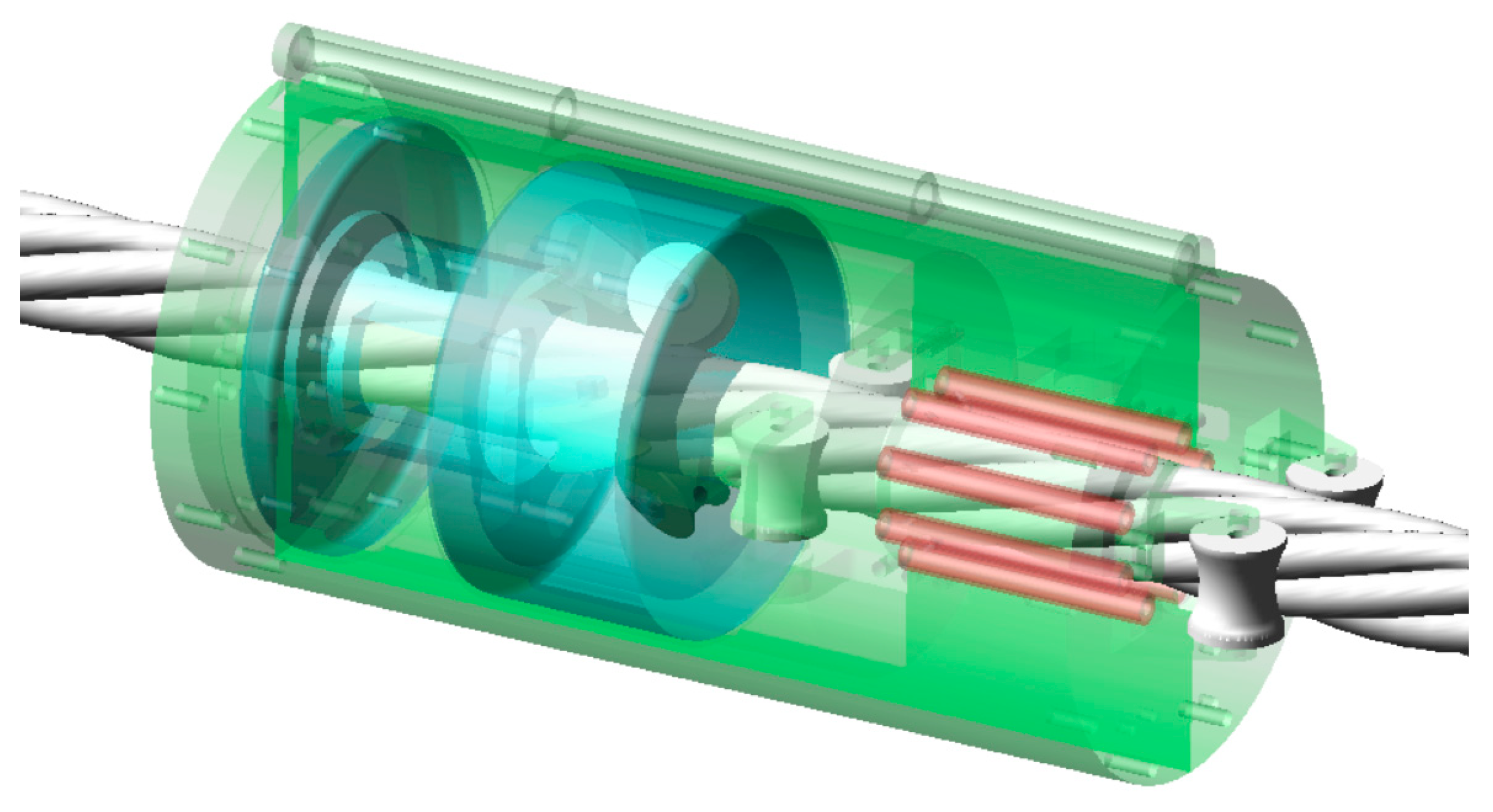
2. Structure
3. Static Analysis
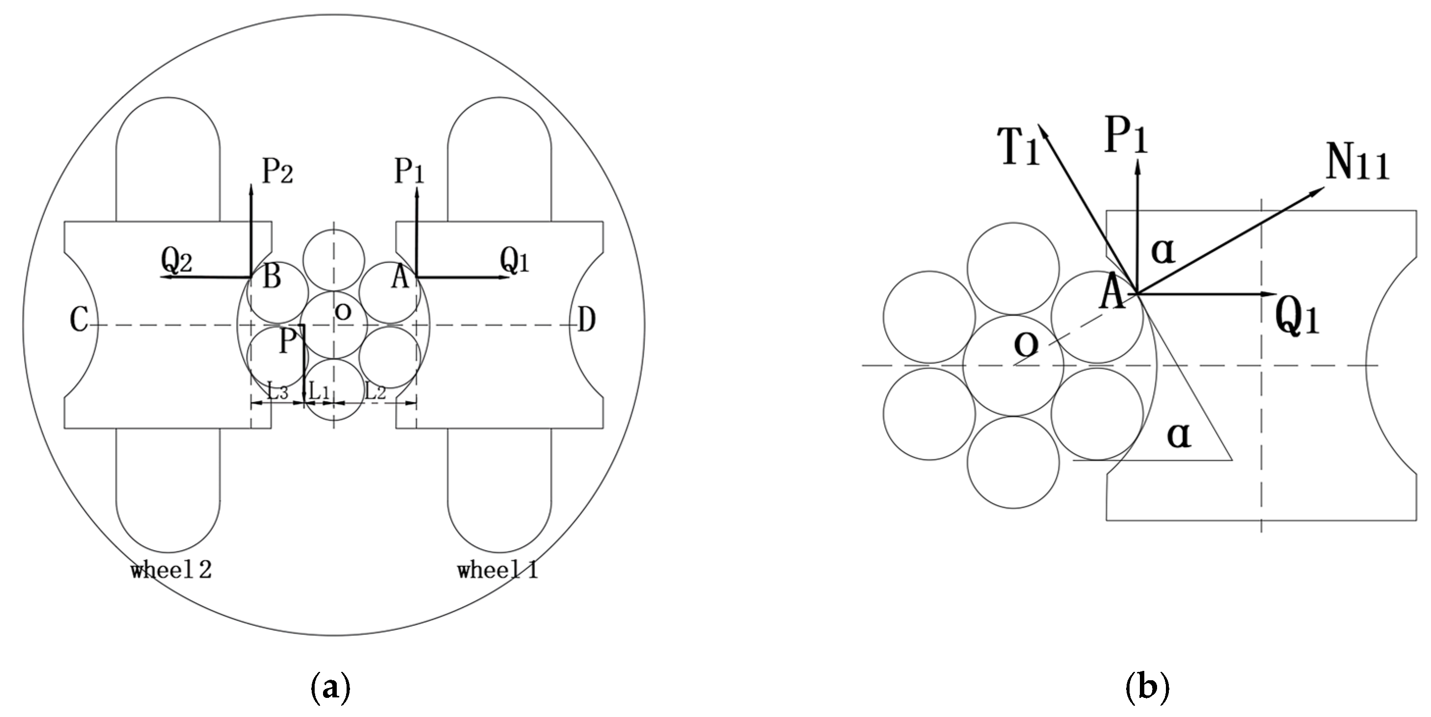
3.1. Static Analysis of the Guide Wheels
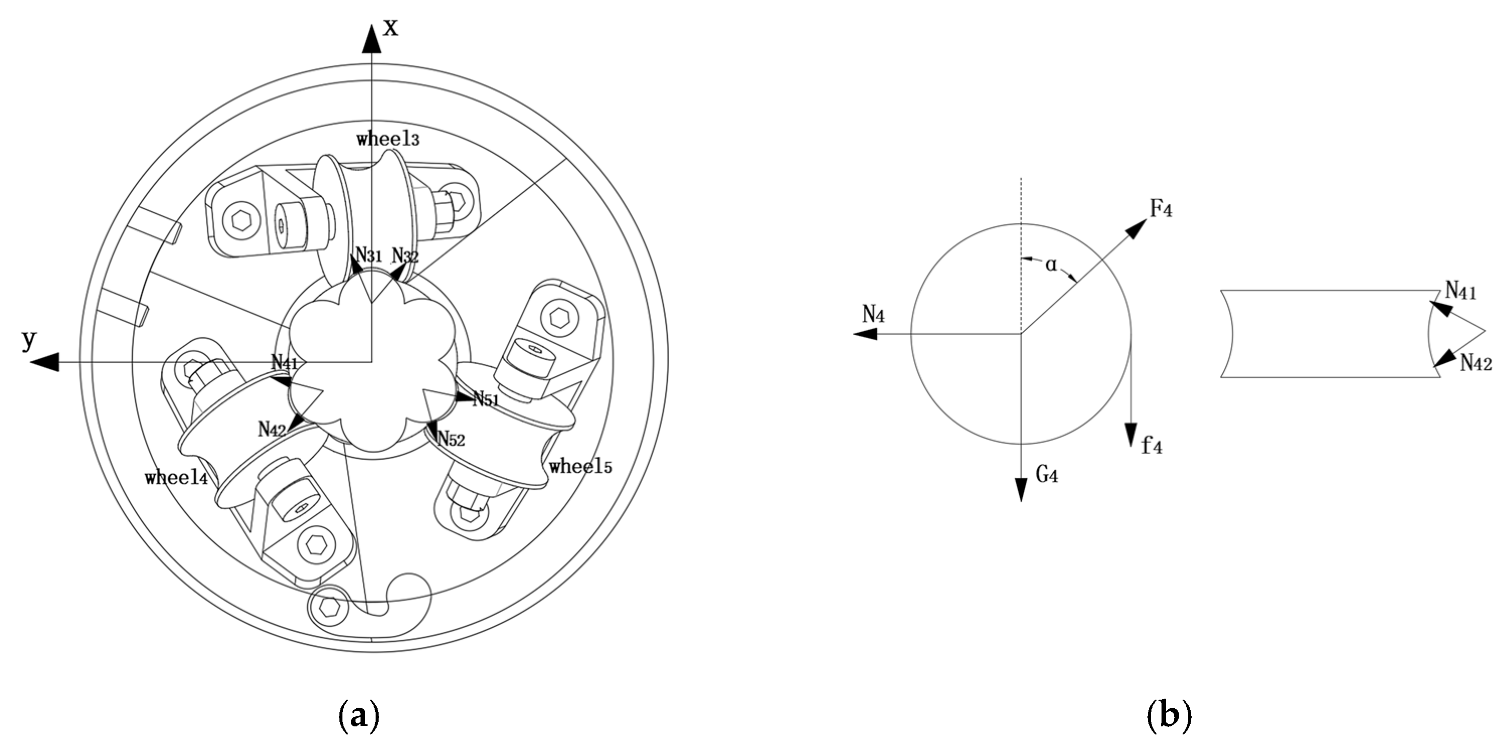
3.2. Static Analysis of the Twist Wheels
4. Kinematic Analysis
- In the process of climbing obstacles, the device does not always rotate around the wire rope. There are two guide wheels outside, while the two internal guide wheels and three twist U-shaped wheels with 120° spacing rotate around the wire rope.
- During the climbing process, there is relative sliding between the moving wheel of the device and the contact point.
- In the climbing process, there is an error in the lay distance of the wire rope, and the axis of the wire rope maintenance device may be offset from the center of the wire rope at a certain angle during operation.
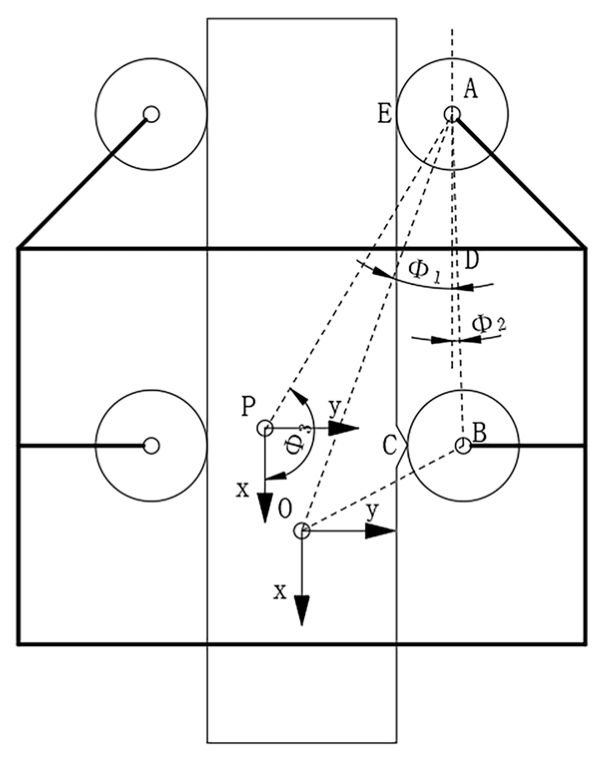
4.1. Kinematic Analysis of the Guide Wheels
4.2. Kinematic Analysis of the Twist Wheels
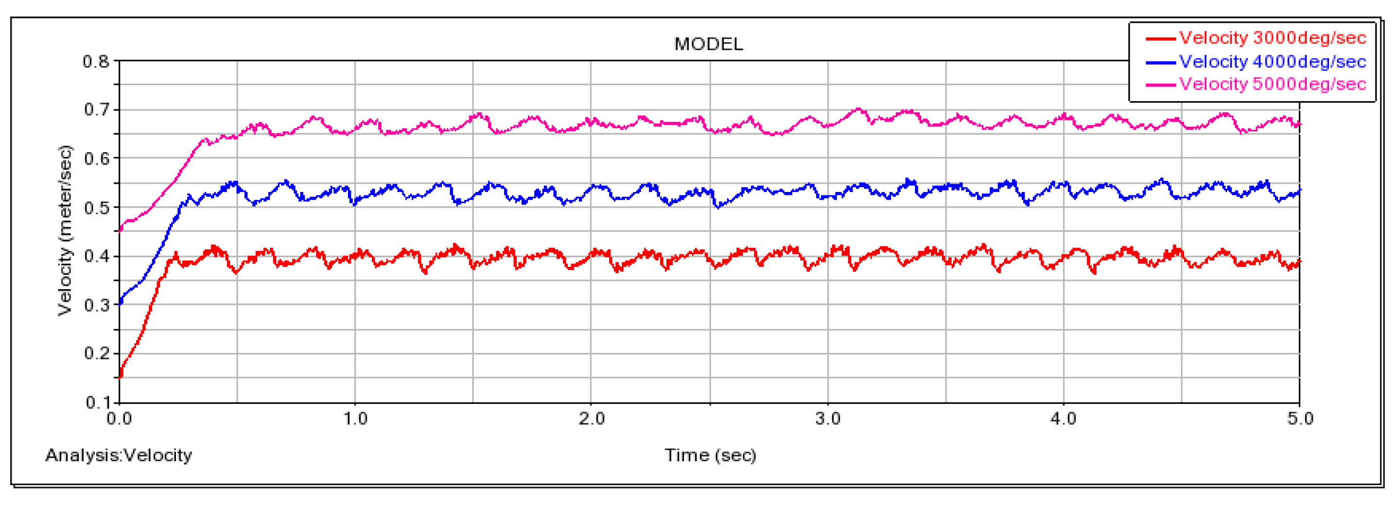
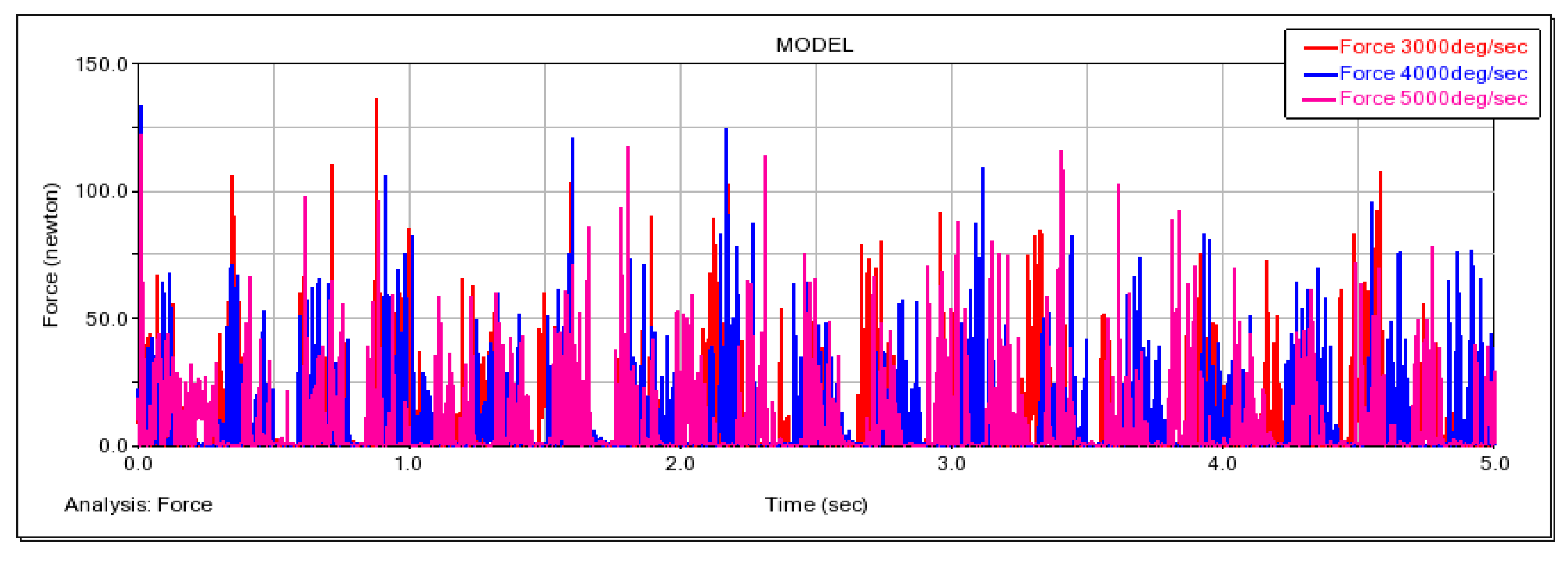
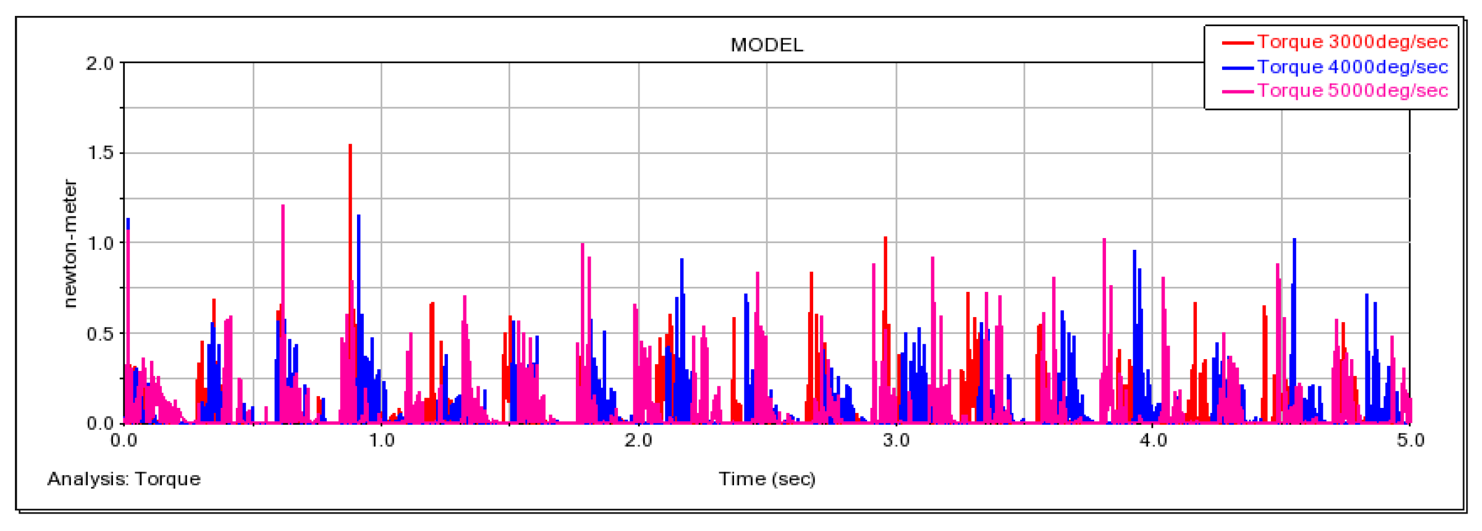
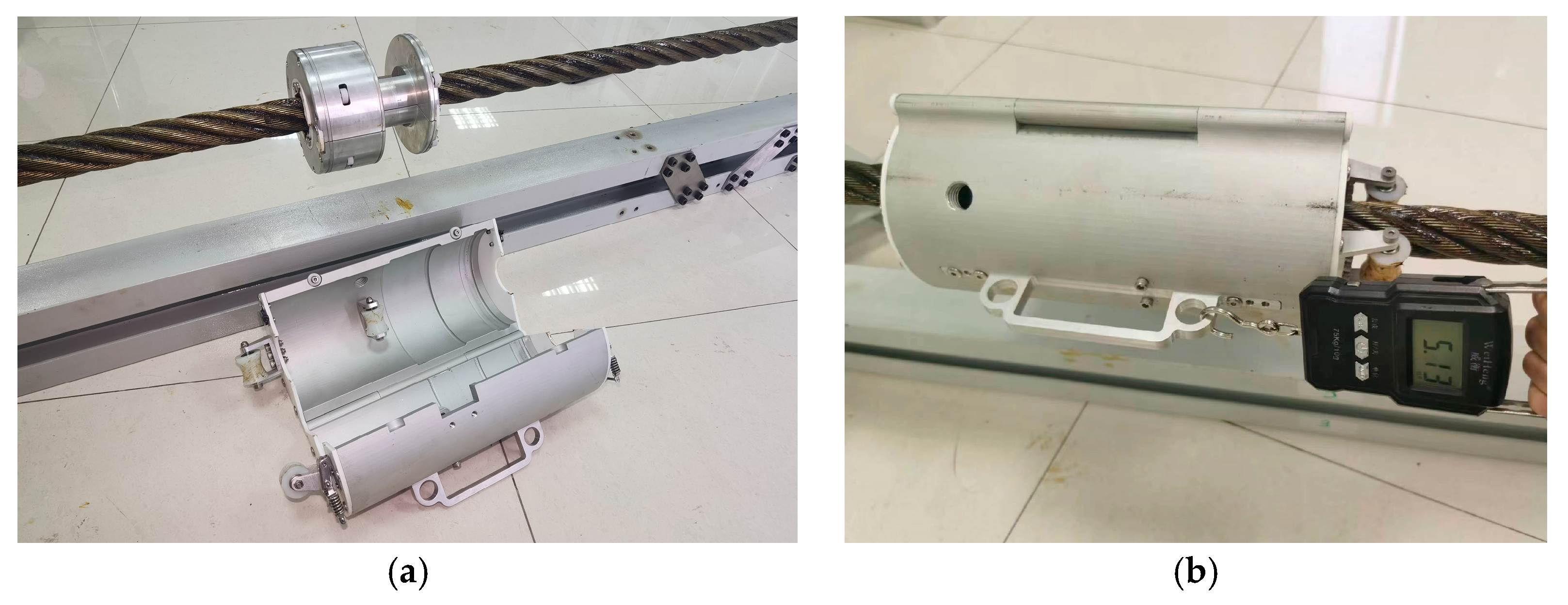
5. Experiments
6. Conclusions and Future Work
Author Contributions
Funding
Data Availability Statement
Conflicts of Interest
Abbreviations
| Two points of contact between the guide wheel and the wire rope | Total mass of the device | ||
| Normal reaction on the upper side of the right guide wheel’s surface | Normal reaction under the right guide wheel’s surface | ||
| Normal reaction on the upper side of the left guide wheel’s surface | Normal reaction under the left guide wheel’s surface | ||
| Tangential reaction of the wire rope to the guide wheel | Vertical force at the point of contact between the guide wheel and the wire rope | ||
| Transverse force at the point of contact between the guide wheel and the wire rope | Angle between the normal reaction and the vertical direction | ||
| Friction coefficient between the guide wheel and wire rope’s surface | Distance from the center of mass to the vertical line of the wire rope | ||
| Vertical distance between the contact point of the guide wheel and the center of the wire rope | Vertical distance between the contact point of the guide wheel, wire rope, and the wire rope’s center of mass | ||
| Acceleration of transverse vibration of the wire rope | Acceleration of gravity | ||
| Twist the normal force to the upper side of the wheel’s surface(i = 3, 4, 5) | Apply the normal reaction to the lower side of the wheel’s surface(i = 3, 4, 5) | ||
| Normal force on the surface of the twist wheel | Friction force on the surface of the twist wheel | ||
| Friction coefficient of the twist wheel’s surface | Supporting force of the twist wheel’s fixed seat against the twist wheel | ||
| Pressure between the underside of the rotor and the housing | Twist wheel radius | ||
| Resistance of lubricating oil to the movement of the twist wheel | Friction between the bottom of the rotor and the housing | ||
| Friction between the side of the rotor and the inside of the housing | Coefficient of sliding friction between the rotor surface and housing | ||
| Resistance between the lower surface of the rotor and the grease | Resistance between the upper surface of the rotor and the grease | ||
| Resistance difference between the upper and lower surfaces of the rotor | Fluid pressure | ||
| Grease density | Radius of the guide wheel | ||
| Radius of wire rope | Angle between the line between the center of the guide wheel and the center of the scraper and the vertical line (acute Angle) | ||
| Deviation angle (acute angle) of the unilateral two-wheel centerline relative to the wire rope axis | Angle between guide wheel center A and the scraper center and vertical line (obtuse Angle) | ||
| Center point speed of guide wheel A | Center speed of guide wheel B | ||
| Center point acceleration of guide wheel A | Center point acceleration of guide wheel B | ||
| Angular velocity of bar AB | Angular acceleration of the AB bar | ||
| Center of gravity coordinates of the device | Center of gravity velocity of device | ||
| Acceleration of the center of gravity of the device | The angle between the center axis of the scraper and the center axis of the twist wheel | ||
| Twist wheel inclination | Distance between the center of the twist wheel and the x-y plane of the twist wheel support | ||
| Point of contact between the twist wheel and the wire rope (j = 0, 1, 2, i = 1, 2, 3) | Speed of the guide wheel in normal working condition | ||
| Speed of the twist wheel in normal working condition | Pitch of the wire rope |
References
- Patil, M.B.P.; Chaudhari, H.D. Wire rope lubrication system for harbor mobile cranes. Int. J. Eng. Sci. Res. Technol. 2018, 7, 227–231. [Google Scholar]
- Zheng, M.; Li, Y.; Li, J.; Yuan, K. Structure design and kinematical analysis of a new type cable climbing robot. In Proceedings of the 2010 Second International Conference on Intelligent Human-Machine Systems and Cybernetics, Nanjing, China, 26–28 August 2010; Volume 1, pp. 284–287. [Google Scholar]
- Kim, H.M.; Cho, K.H.; Jin, Y.H.; Liu, F.; Choi, H.R. Development of a climbing robot for inspection of bridge cable. J. Korea Robot. Soc. 2012, 7, 83–91. [Google Scholar] [CrossRef]
- Xi, F.; Jiang, Q. Dynamic obstacle-surmounting analysis of a bilateral-wheeled cable-climbing robot for cable-stayed bridges. Ind. Robot-Int. J. Robot. Res. Appl. 2019, 46, 431–443. [Google Scholar] [CrossRef]
- dos Santos, C.H.F.; Abdali, M.H.; Martins, D.; Alexandre, C.B.A. Geometrical motion planning for cable-climbing robots applied to distribution power lines inspection. Int. J. Syst. Sci. 2021, 52, 1646–1663. [Google Scholar] [CrossRef]
- Jiang, W.; Ye, G.C.; Zou, D.H.; Yan, Y. Mechanism configuration and innovation control system design for power cable line mobile maintenance robot. Robotica 2021, 39, 1251–1263. [Google Scholar] [CrossRef]
- Wang, Z.; He, B.; Zhou, Y.; Liu, K.; Zhang, C. Design and implementation of a cable inspection robot for cable-stayed bridges. Robotica 2021, 39, 1417–1433. [Google Scholar] [CrossRef]
- Fang, G.; Cheng, J. Design and implementation of a wire rope climbing robot for sluices. Machines 2022, 10, 1000. [Google Scholar] [CrossRef]
- Chen, G.; Yang, H.; Cao, H.; Ji, S.; Zeng, X.; Wang, Q. Design of an embracing-type climbing robot for variation diameter rod. Ind. Robot-Int. J. Robot. Res. Appl. 2019, 46, 56–72. [Google Scholar] [CrossRef]
- Li, P.; Duan, X.; Sun, G.; Li, X.; Zhou, Y.; Liu, Y. Design and control of a climbing robot for inspection of high mast lighting. Assem. Autom. 2019, 39, 77–85. [Google Scholar] [CrossRef]
- Kim, H.M.; Cho, K.H.; Liu, F.; Choi, H. Development of cable climbing robotic system for inspection of suspension bridge. In Proceedings of the 28th International Symposium on Automation and Robotics in Construction, ISARC, Seoul, Republic of Korea, 29 June–2 July 2011. [Google Scholar]
- Kim, H.M.; Cho, K.H.; Jin, Y.H.; Liu, F.; Koo, J.C.; Choi, H.R. Development of cable climbing robot for maintenance of suspension bridges. In Proceedings of the 2012 IEEE International Conference on Automation Science and Engineering (CASE), Seoul, Republic of Korea, 20–24 August 2012; pp. 606–611. [Google Scholar] [CrossRef]
- Cho, K.H.; Jin, Y.H.; Kim, H.M.; Moon, H.; Choi, H.R. Caterpillar-based cable climbing robot for inspection of suspension bridge hanger rope. In Proceedings of the Automation Science and Engineering (CASE), Madison, WI, USA, 17–20 August 2013. [Google Scholar]
- Cho, K.H.; Kim, H.M.; Jin, Y.H.; Liu, F. Inspection robot for hanger cable of suspension bridge: Mechanism design and analysis. IEEE/ASME Trans. Mechatron. 2013, 18, 1665–1674. [Google Scholar] [CrossRef]
- Cho, K.H.; Jin, Y.H.; Kim, H.M.; Moon, H.; Koo, J.C.; Choi, H.R. Multifunctional robotic crawler for inspection of suspension bridge hanger cables: Mechanism design and performance validation. IEEE/ASME Trans. Mechatron. 2017, 22, 236–246. [Google Scholar] [CrossRef]
- Xu, F.; Wang, X.; Wang, L. Cable inspection robot for cable-stayed bridges: Design, analysis, and application. J. Field Robot. 2011, 28, 441–459. [Google Scholar] [CrossRef]
- Xu, F.; Hu, J.; Wang, X.; Jiang, G. Helix cable-detecting robot for cable-stayed bridge: Design and analysis. Int. J. Robot. Autom. 2014, 29, 406–414. [Google Scholar] [CrossRef]
- Xu, F.; Hu, J.L.; Jiang, G. The obstacle-negotiation capability of rod-climbing robots and the improved mechanism design. J. Mech. Sci. Technol. 2015, 29, 2975–2986. [Google Scholar] [CrossRef]
- Xu, F.; Shen, J.; Jiang, G. Kinematic and dynamic analysis of a cable-climbing robot. Int. J. Adv. Robot. Syst. 2015, 12, 99. [Google Scholar] [CrossRef]
- Xu, F.; Jiang, Q.; Lv, F.; Wu, M.; Zhang, L. The dynamic coupling analysis for all-wheel-drive climbing robot based on safety recovery mechanism model. Appl. Sci. 2018, 8, 2123. [Google Scholar] [CrossRef]
- Ho, H.-N.; Kim, K.-D.; Park, Y.-S.; Lee, J.-J. An efficient image-based damage detection for cable surface in cable-stayed bridges. Ndt. E Int. 2013, 58, 18–23. [Google Scholar] [CrossRef]
- Park, S.; Kim, J.-W.; Lee, C.; Lee, J.-J. Magnetic flux leakage sensing-based steel cable nde technique. Shock Vib. 2014, 2014, 929341. [Google Scholar] [CrossRef]
- Song, Y.; Wang, H.; Zhang, J. A vision-based broken strand detection method for a power-line maintenance robot. IEEE Trans. Power Deliv. 2014, 29, 2154–2161. [Google Scholar] [CrossRef]
- Li, X.; Gao, C.; Guo, Y.; He, F.; Shao, Y. Cable surface damage detection in cable-stayed bridges using optical techniques and image mosaicking. Opt. Laser Technol. 2019, 110, 36–43. [Google Scholar] [CrossRef]
- Ji, Q.; Jian-Bin, L.; Fan-Rui, L.; Jian-Ting, Z.; Xu, W. Stress evaluation in seven-wire strands based on singular value feature of ultrasonic guided waves. Struct. Health Monit. 2022, 21, 518–533. [Google Scholar] [CrossRef]
- Ma, W.; Zhu, Z.C.; Xu, L.; Chen, G.A. Sliding friction and wear properties of friction linings with friction-promoting grease applied. Proc. Inst. Mech. Eng. Part J J. Eng. Tribol. 2014, 228, 595–607. [Google Scholar] [CrossRef]
- Dundu, M.; Ward, M. The effects of grease and tendon mass variances on the coefficient of friction in unbonded post-tensioning tendons. J. S. Afr. Inst. Civ. Eng. 2016, 58, 62–65. [Google Scholar] [CrossRef]
- Feng, C.; Zhang, D.; Chen, K.; Guo, Y. Study on viscoelastic friction and wear between friction linings and wire rope. Int. J. Mech. Sci. 2018, 142, 140–152. [Google Scholar] [CrossRef]
- Dyson, C.J.; Chittenden, R.J.; Priest, M.; Fox, M.F.; Hopkins, W.A. Representative tribometer testing of wire rope fretting contacts: The effect of lubrication on fretting wear. Tribol. Trans. 2020, 63, 557–574. [Google Scholar] [CrossRef]
- Feng, C.; Zhang, D.; Grecov, D.; Chen, K. Effect of rheological properties of friction-enhancing greases on the friction between friction lining and wire rope. Tribol. Int. 2020, 144, 106143. [Google Scholar] [CrossRef]
- Kupka, I.; Hartl, M.; Lika, M. Thin lubricating films behaviour at very high contact pressure. Tribol. Int. 2006, 39, 1726–1731. [Google Scholar] [CrossRef]
- Takeaki, T. Coating flows of power-law non-newtonian fluids in slot coating. Nihon Reoroji Gakkaishi 2011, 38, 223–230. [Google Scholar]
- Seiwert, J.; Quere, D.; Clanet, C. Flexible scraping of viscous fluids. J. Fluid Mech. 2013, 715, 424–435. [Google Scholar] [CrossRef]
- Guo, L.; Wong, P.L.; Guo, F. Effects of viscosity and sliding speed on boundary slippage in thin film hydrodynamic lubrication. Tribol. Int. 2017, 107, 85–93. [Google Scholar] [CrossRef]
- Smit, W.J.; Kusina, C.; Joanny, J.-F.; Colin, A. Stress field inside the bath determines dip coating with yield-stress fluids in cylindrical geometry. Phys. Rev. Lett. 2019, 123, 148002. [Google Scholar] [CrossRef] [PubMed]
- Zhang, Z.; Wang, Y.; Lin, J.; Wang, D. Study on factors influencing film formation of grease and calculation model for grease film thickness. Greases 2022, 10, 123. [Google Scholar] [CrossRef]


| Weight | 3 kg |
|---|---|
| Radius of the guide wheels | 14 mm |
| Radius of the guide wheels | 15 mm |
| Radius of the wire rope | 20 mm |
| Pitch of the wire rope | 300 mm |
| Twist wheel inclination | 15° |
| Startup Speed | Traction Force |
|---|---|
| 0.4 m/s | 51.3 N |
| 0.6 m/s | 107.7 N |
| 0.8 m/s | 147.3 N |
Disclaimer/Publisher’s Note: The statements, opinions and data contained in all publications are solely those of the individual author(s) and contributor(s) and not of MDPI and/or the editor(s). MDPI and/or the editor(s) disclaim responsibility for any injury to people or property resulting from any ideas, methods, instructions or products referred to in the content. |
© 2023 by the authors. Licensee MDPI, Basel, Switzerland. This article is an open access article distributed under the terms and conditions of the Creative Commons Attribution (CC BY) license (https://creativecommons.org/licenses/by/4.0/).
Share and Cite
Wang, W.; Yang, H.; Chen, Y.; Huang, X.; Cao, J.; Zhang, W. Motion Analysis of Wire Rope Maintenance Device. Actuators 2023, 12, 392. https://doi.org/10.3390/act12100392
Wang W, Yang H, Chen Y, Huang X, Cao J, Zhang W. Motion Analysis of Wire Rope Maintenance Device. Actuators. 2023; 12(10):392. https://doi.org/10.3390/act12100392
Chicago/Turabian StyleWang, Wei, Hao Yang, Yan Chen, Xudong Huang, Jinlong Cao, and Weilun Zhang. 2023. "Motion Analysis of Wire Rope Maintenance Device" Actuators 12, no. 10: 392. https://doi.org/10.3390/act12100392
APA StyleWang, W., Yang, H., Chen, Y., Huang, X., Cao, J., & Zhang, W. (2023). Motion Analysis of Wire Rope Maintenance Device. Actuators, 12(10), 392. https://doi.org/10.3390/act12100392