1. Introduction
Vibration presents substantial challenges in aerospace engineering, as it embodies unwanted energy that can trigger aeroelastic instability, particularly flutter. Additionally, aircraft vibration can induce fatigue, generate excessive noise, and cause discomfort for passengers and crew. Consequently, it becomes imperative to implement efficient vibration control methods to ensure both structural integrity and overall vehicle safety. Among the various vibration control strategies, passive control usually uses dynamic vibration absorbers (DVAs), which are extensively employed for controlling structural vibrations [
1,
2,
3,
4,
5]. However, one drawback of DVAs is their limited effectiveness in attenuating vibrations at multiple resonance frequencies. Significant advancements have been achieved by implementing inertial actuators (or proof mass actuators) [
6,
7], resulting in improved reduction of vibrations across multiple resonance frequencies [
8]. These actuators exhibit enhanced adaptability to changes in controlled structural parameters, making them suitable for a wide range of operating conditions including low-frequency scenarios where precise vibration control is required. Over the past two decades, inertial actuators have found extensive use as vibration and structural sound suppression devices, demonstrating their high effectiveness in reducing vibrations during bridge construction [
9] and minimizing noise levels in aircraft cabins, thereby enhancing safety and passenger comfort [
10,
11].
To date, many active vibration control (AVC) strategies have utilized a centralized architecture based on negative velocity feedback, which allows for precise damping of structural vibrations [
12,
13,
14,
15]. However, as the control system expands, potential issues may arise, particularly in cases of sensor failure, which can result in a complete system breakdown. In contrast, a totally decentralized control strategy allows each control unit to operate independently, also known as self-sufficient controllers [
16,
17]. In this strategy, inertial actuators and accelerometers are employed, with their signals processed by a time integrator to serve as control units in active control systems, enabling precise control over structural vibrations. To ensure system stability, it is crucial to align the sensors and actuators perfectly during application. However, this method often presents imperfect alignment control during installation [
18]. If the inertial actuator and sensor are designed as a monolithic structure, perfect alignment of the system can be ensured and the stability of the system is theoretically guaranteed [
19].
On the other hand, the distributed control strategy in vibration control systems often necessitates complex alignment of each control unit [
20,
21]. A massive number of sensors and actuators need to be installed and the operation is very complex [
22]. Meanwhile, commercially available velocity sensors currently suffer from drawbacks such as their large size, high cost, and inconvenient usage [
23]. Additionally, displacement sensors or acceleration sensors require corresponding circuitry to convert their outputs into velocity signals. To overcome the drawback of complex alignment, a novel solution has been developed: a self-sufficient control unit [
17]. This innovative device enables precise alignment control and integrates a compact, portable velocity sensor directly into the control unit, eliminating the need for external circuit modules. It combines the basic elements of a control unit, containing a velocity sensor for vibration detection and an actuator driven by a control signal.
Apart from the design of the inertial actuators, selecting an appropriate active control algorithm is crucial to improve control efficiency. One rather appealing solution for the active control of broadband vibration is using self-contained control units with direct velocity feedback (DVBF) laws implemented through velocity sensors and collocated inertial actuator pairs. These control units are achieved by employing a velocity sensor or an accelerometer processed by an external integrated circuit and a parallel inertial actuator pair, eliminating the need for an external support to react off; thus, the control unit is simple to mount on the structure to be controlled [
24].
Earlier work focused on implementing a decentralized array of DVBF control units with the ability to adjust the feedback gain to reduce the structure’s vibration significantly [
25]. Additionally, Zilletti et al. [
26] demonstrated that maximizing power absorption is equivalent to minimizing the kinetic energy if the primary structure is an SDOF structure. By increasing the feedback gain, the peak resonance frequency of the SDOF system decreases due to the active damping effect. However, the dynamic behavior of the inertial actuator leads to overflow at its resonant frequency, making the system unstable as the feedback gain approaches the maximum steady-state gain. To solve this problem, the optimal feedback gain of the vibration control board can be achieved by maximizing the power absorption [
27,
28]. Moreover, the margin of feedback gain can be further improved by phase compensation of inertial actuators or other control algorithms, thus enhancing the stability of the system.
Among these control algorithms, positive position feedback (PPF) stands out as a second-order low-pass filter widely used in structural vibration control due to its simplicity, robustness, and effectiveness in addressing high-frequency signal saturation [
29,
30,
31,
32]. Notably, Fanson and Caughey first proposed the PPF control technique; PPF is insensitive to the uncertainty of the structure’s natural damping ratio, providing stable and reliable vibration control [
33,
34,
35]. The term “positive position” refers to feeding position measurements into the compensator in a positive manner and positively feeding position signals from the compensator back to the structure [
3]. This characteristic makes this algorithm well-suited for collocated actuator/sensor pairs [
36,
37,
38]. Previous research by Friswell and Inman proposed PPF control as an output feedback controller, using optimal control technology to address the instability problem caused by not considering mode overflow in the SDOF system. The effectiveness of this method was verified using centralized and distributed control architectures [
39]. Similarly, Sim and Lee used an accelerated feedback (AFC) strategy employing second-order filters, also known as resonant controllers, to target desired modes of multi-degree-of-freedom systems [
40,
41]. Zhao et al. studied the application of a nonlinear positive position feedback controller with Duffing oscillator and derived the closed expression of optimal control parameters [
42]. As a result, the low-pass filter as a PPF controller has been shown to work well for signal or multimodal control [
43].
However, using multiple low-pass filters as PPF controllers to control multimodal vibrations may lead to phase overlap and potential multimodal control problems. The combined action of multiple PPF controllers affects the overall phase response of the system, making it challenging to control multiple modes simultaneously. Furthermore, incorrect placement of the second PPF controller may interfere with the operation of the first one, rendering it ineffective [
44]. To enhance the control stability of the inertial actuator under the DVBF method, this study adopts a bandpass filter based on the second-order compensator principle proposed by Rohlfing [
14]. The objective is to address the problem and improve the traditional DVBF stability. By adjusting the center frequency and damping of each bandpass filter, precise control of different modes can be achieved; then, overall system stability can be improved. This method offers a promising solution for improving phase-related issues and enhancing the effectiveness of multimodal control in vibration reduction.
The rest of this study is structured as follows. In
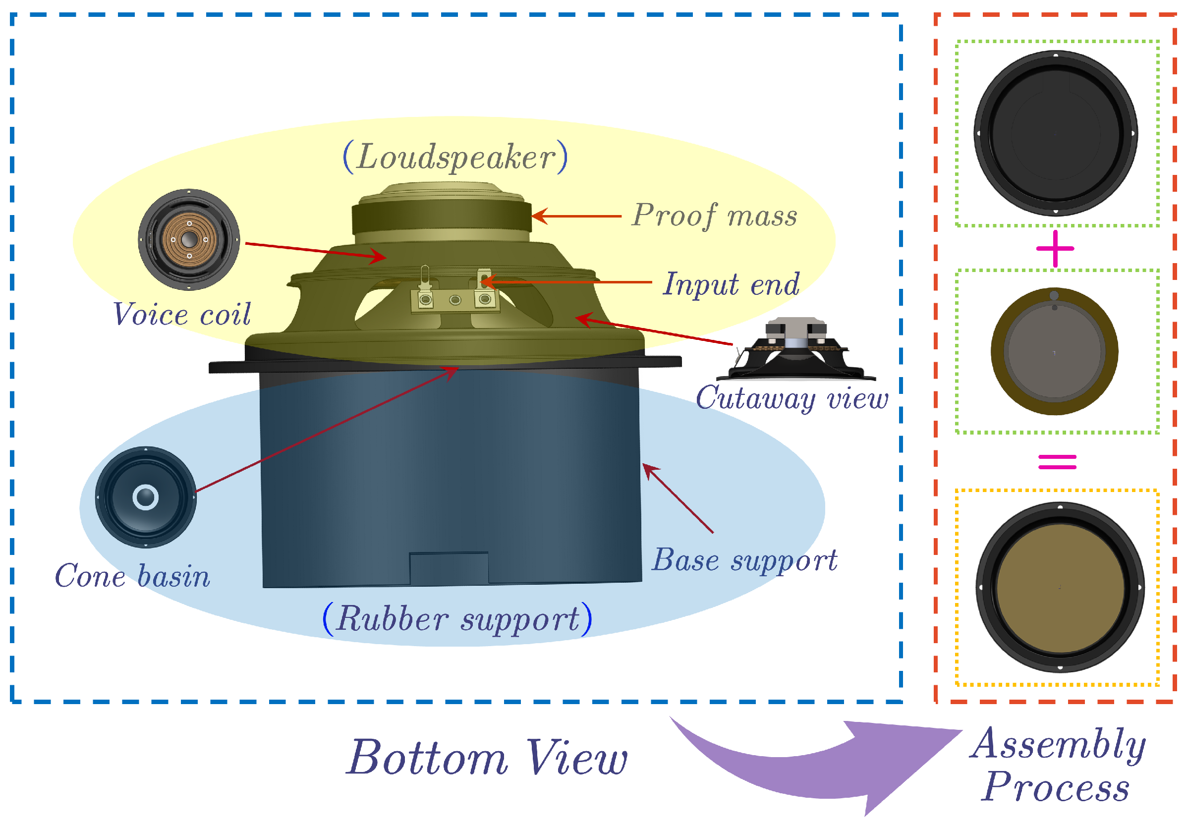
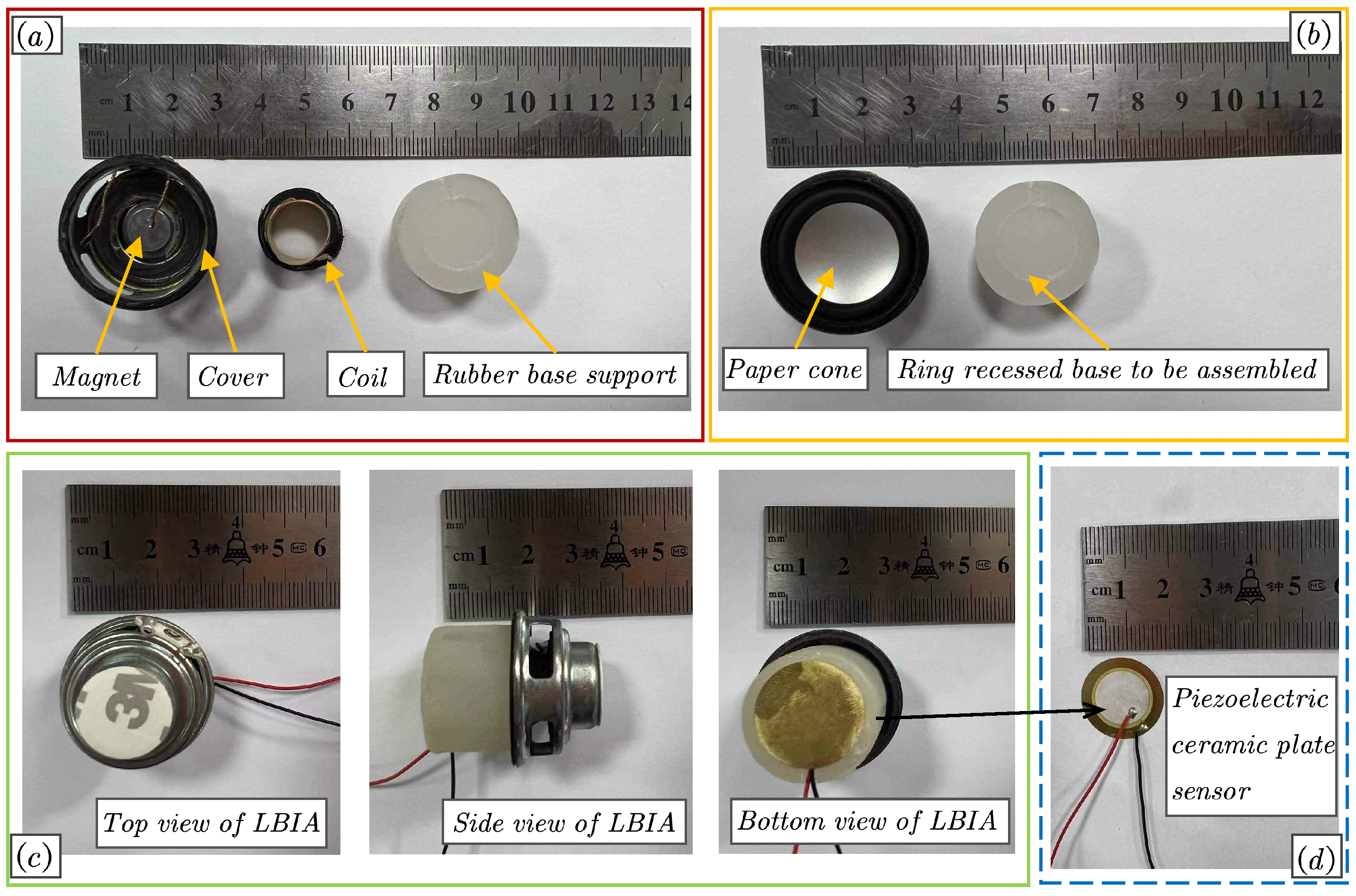
Section 2, the designed loudspeaker-based inertial actuator with an integrated piezoelectric sensor will be described and experimentally verified.
Section 3 presents the control performances of the proposed LBIA by using the DVBF approach for thin plate structures. In addition, the piezoelectric sensor model of the integrated control unit is established. In
Section 4, a parallel connection of multiple bandpass filters is used as a controller to improve the control performance based on the proposed LBIA; then, the corresponding experimental results are presented.
Section 5 concludes with a discussion and summary of the relevant research results and experimental conclusions.
3. Control Performance of LBIA with Integrated Piezoelectric Sensor by Using Strain Differential Feedback (SDF) Approach
In this section, our focus is to discuss the effectiveness of the integrated design as a control unit for thin plate structures. To demonstrate this, we utilize the strain differential feedback (SDF) approach based on the integrated piezoelectric ceramic sensor.
Figure 7 illustrates the behavior of the piezoelectric ceramic sensor under the influence of a stress field. When the sensor senses structural vibrations, it generates the corresponding induced electricity. According to [
46], the induced charge generated by piezoelectric ceramic sensors can be described by Equation (
8) as follows:
where
is the polar coordinate form of displacement of the thin plate,
e is the piezoelectric strain constant of the sensor,
R is the radius of the selected circular piezoelectric ceramic sensor, and
and
represent the central position of the piezoelectric ceramic sensor.
As depicted in
Figure 7, the sensor generates a charge signal in response. This signal can be perceived as a voltage source connected in series with the capacitor. Once connected to a signal conditioning circuit—specifically, a current amplifier—the output signal undergoes conversion into a current signal. Reference [
47] provides insights into the understanding of this process from both physical and mathematical perspectives, assuming the piezoelectric strain constant and alignment with the Y-axis. Essentially, it involves differentiating Equation (
8) once. The current output of piezoelectric ceramics is expressed as follows:
Equation (
9) can be expressed as
where
and
represent the mth structural modal shape and modal velocity, respectively. The modal index of the structure on the
x and
y axes is represented by
, respectively.
Equation (
10) can be further simplified to matrix form:
The output voltage of the sensor is determined under the assumption that the current amplifier operates ideally with infinite internal resistance:
where
is the amplifier constant.
The combination model of the piezoelectric ceramic sensor and the inertial actuator can be obtained by utilizing the mathematical model of the piezoelectric ceramic sensor and the dynamic model of the inertial actuator:
where
is a direct multiple relationship between the current
I and the velocity
, which is expressed as
.
Finally, the control situation of the actuator and piezoelectric ceramic sensor is expressed as a transfer function:
Meanwhile,
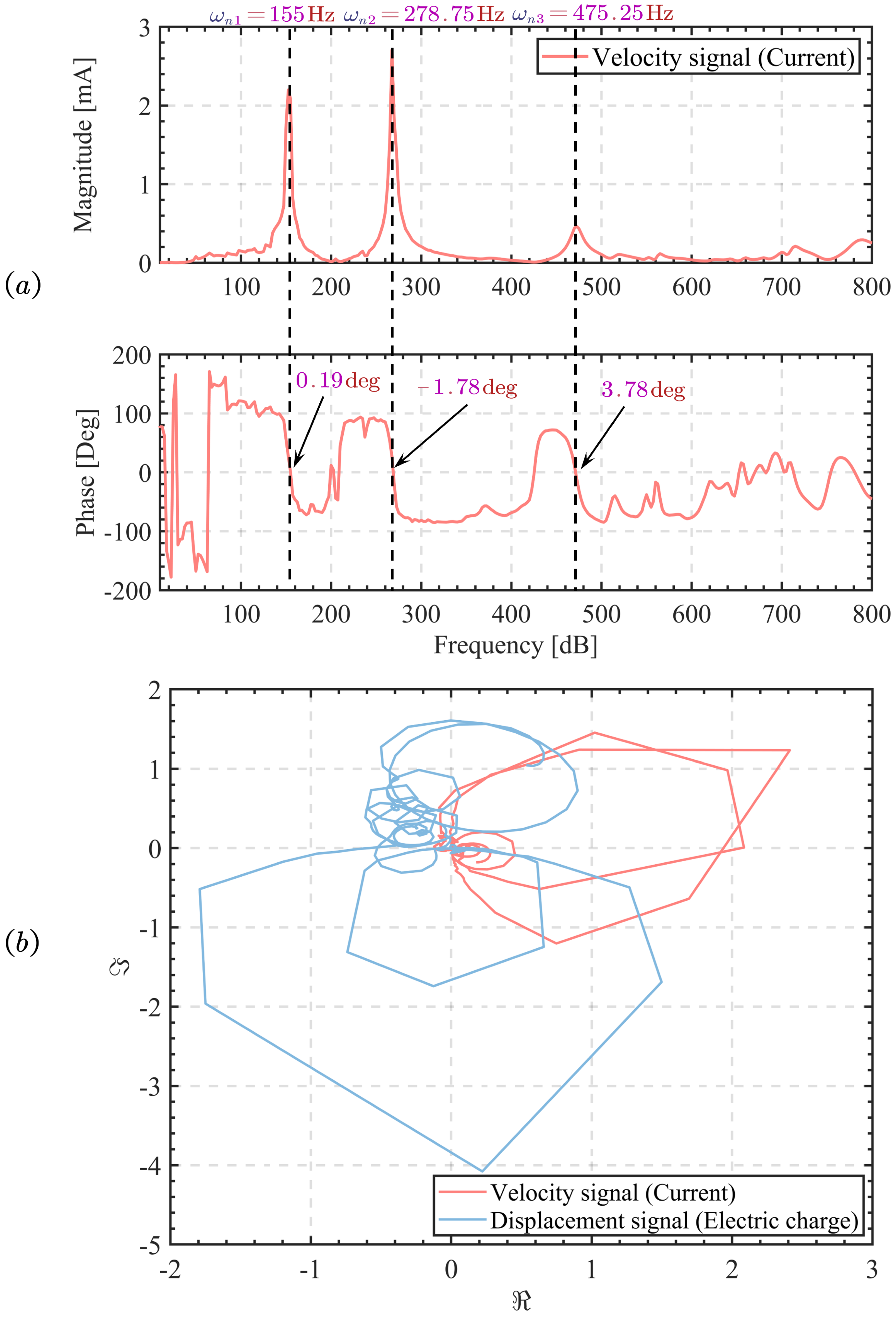
Figure 8b experimentally illustrates the Nyquist diagram of the open-loop transfer function testing before and after signal conditioning of the sensor in the LBIA. The diagram demonstrates the sensor’s ability to convert its charge (displacement signal) into current (velocity signal) after signal conditioning. Notably, it can be seen from
Figure 8a that effective vibration control is achieved when the phase detection indicates that the first and second modes are close to 0 degrees.
Additionally, the fourth mode also exhibits a discernible control effect, as observed in the phase analysis. Moreover, conditioning the signal is accompanied by a 90-degree phase change, resulting from the charge signal transforming into a current signal through the conditioning circuit. It can be described as a differential process, and its specific derivation process is given by Equation (
9). Based on this process, the active vibration control based on it can be referred to as strain differential feedback (SDF) control. In conclusion, this analysis provides valuable support for subsequent experiments.
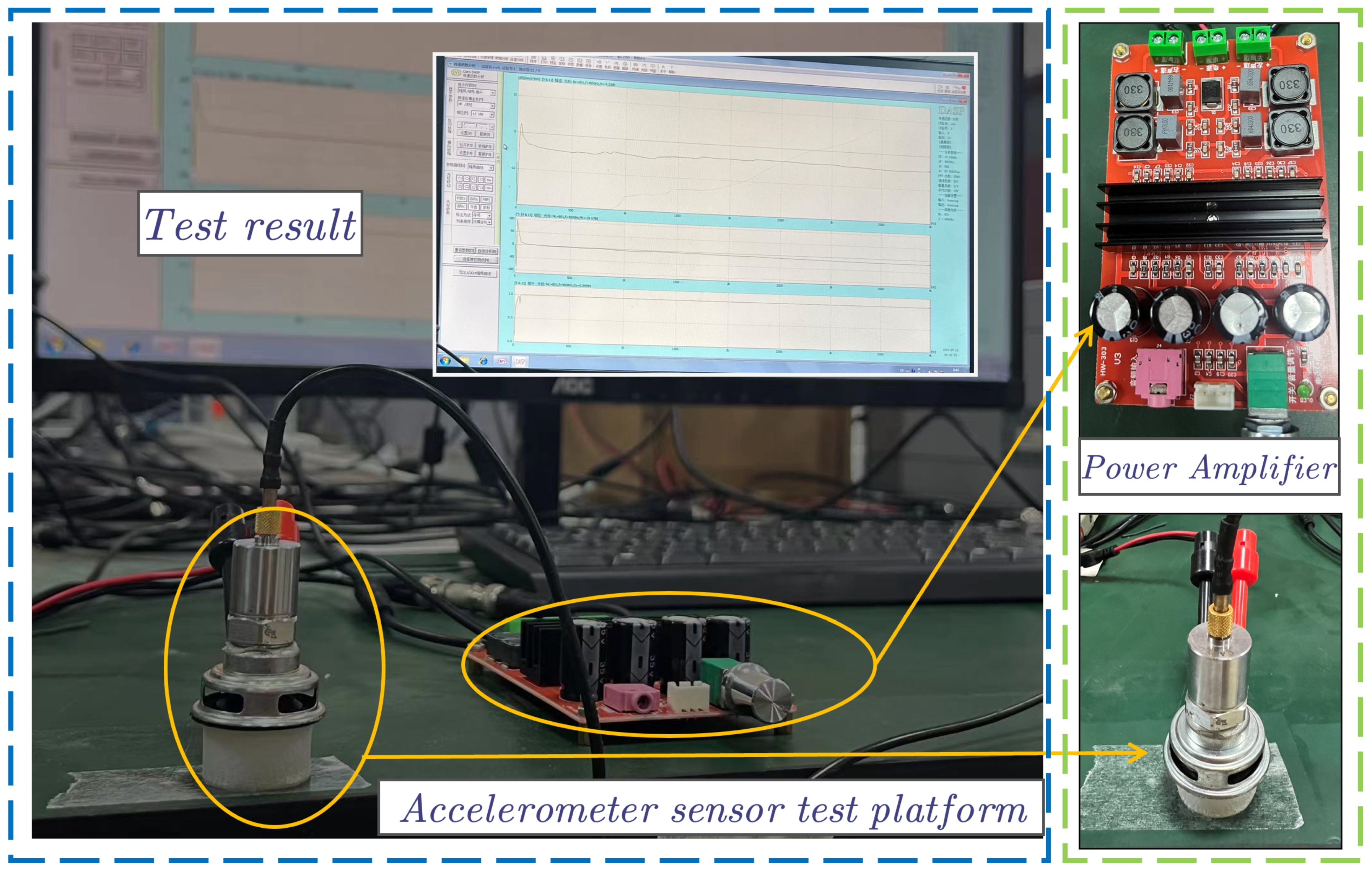
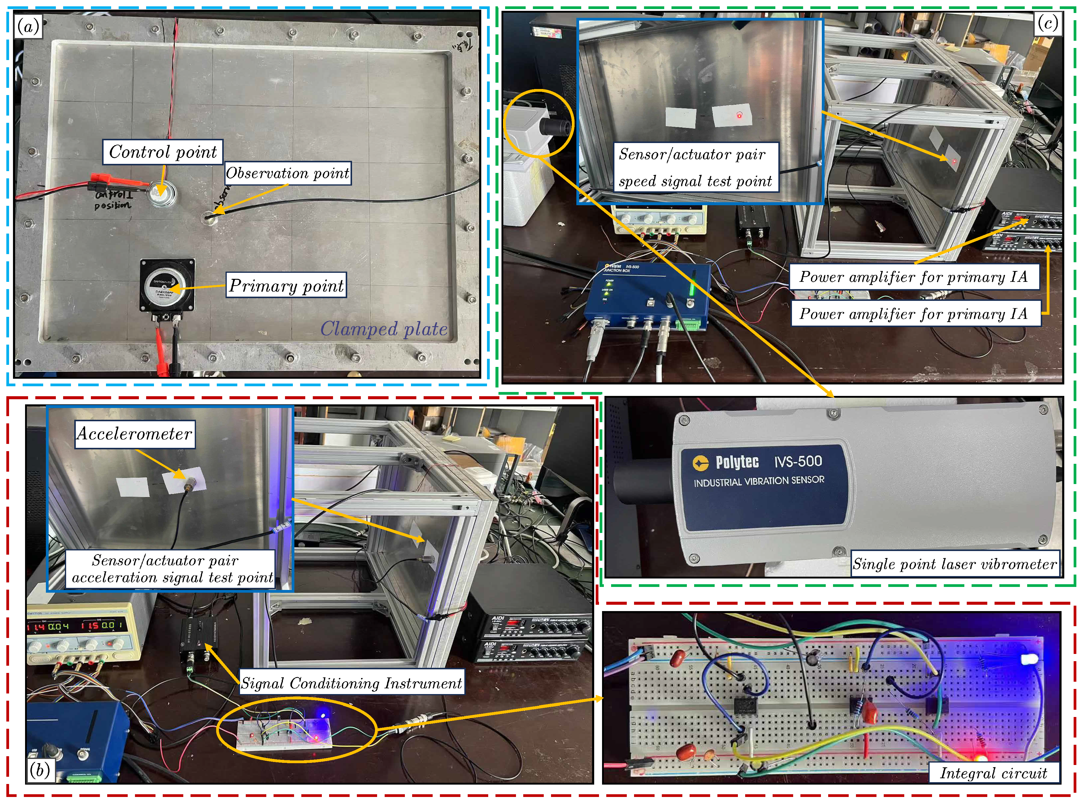
Figure 9 depicts the experimental setup, comprising a thin aluminum plate as the subject of investigation. The geometrical and physical properties of the plate are summarized in
Table 2. To stimulate the structure, a sinusoidal scanning signal, generated by the commercial inertial actuator (DAEX58FP electrodynamic exciter, Nikon, Tokyo, Japan), is used for excitation in a frequency range of 10 Hz to 800 Hz. The vibration signal is collected by a piezoelectric ceramic sensor integrated with LBIA and then passed through the power amplifier to form a closed-loop control system. To ensure a more realistic case study, the primary excitation positions on the board were deliberately chosen to avoid the node lines associated with the previous modes of the structure. The selected position
for the primary source was set at (125 mm, 65 mm). By adopting this approach, the lower-order modes are excited, allowing us to observe the effect of active control on their vibration modes. Similarly, to avoid the node line position, an LBIA with an integrated piezoelectric ceramic sensor is installed at
= (120 mm, 160 mm).
The experiment described in this paper involved collecting vibration energy signals at the same location as LBIA. Specifically, the vibration energy point of the measuring point is on the opposite side of the same-positioned thin plate as LBIA. These signals were obtained using a high-precision laser vibrometer (Polytec IVS-500, Karlsruhe, Germany). In addition to this, an accelerometer sensor was included in
Figure 9 to observe vibrations at different positions. This served as a backup measure in case of laser vibrometer failure, ensuring the test’s success when integrated with the LBIA design that incorporates piezoelectric sensors.
The LBIA, as shown in
Figure 2, is equipped with integrated sensors that facilitate autonomous signal acquisition and output control. Moreover, the open-loop transfer function for LBIA with integrated piezoelectric sensors has been tested, as demonstrated in
Figure 8.
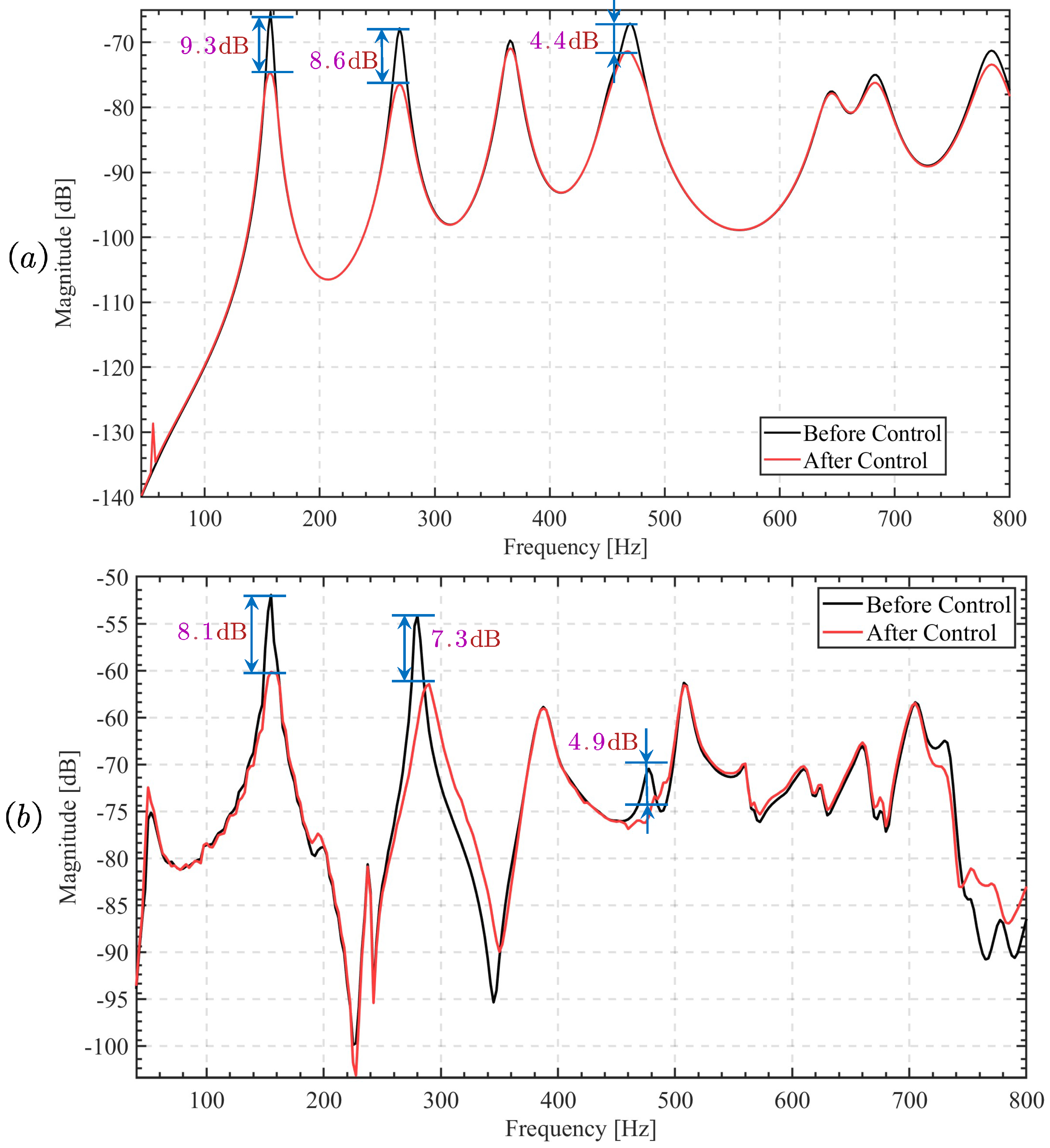
From
Figure 10a, it can be observed that the integrated design of LBIA proves effective in actively controlling the thin plate structure. The vibration energy in the first and second modes reduces by 8.1 dB and 7.3 dB, respectively. There is also some suppression in the fourth mode.
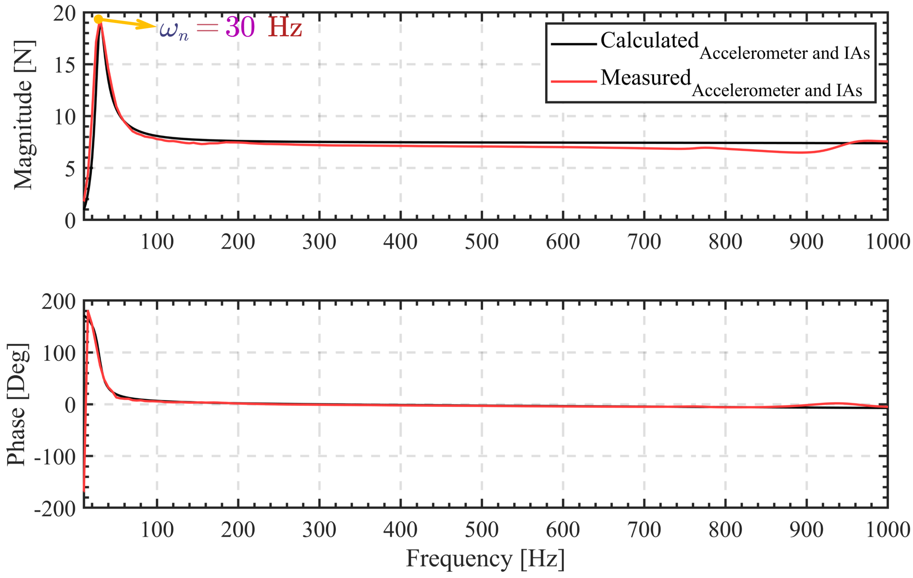
To provide a more accurate assessment of LBIA’s control performance, the control performances for LBIA using DVBF with different external sensors (such as a collocated accelerometer and non-collocated laser vibrometer) are also presented in this study.
Figure 9b illustrates the placement of the accelerometer sensor on the sheet’s back, aligned with the LBIA. Notably, the signal from the accelerometer sensor requires filtering through the signal conditioning instrument before being processed by the time integrator, which converts it into a velocity signal. This step completes the experimental setup for direct velocity feedback. Additionally, as shown in
Figure 9c, the laser vibrometer’s test point is located at the same position as the accelerometer sensor. The laser vibrometer directly collects the velocity signal of the vibration structure as the control signal, offering high acquisition accuracy without requiring any additional signal processing circuit. As a result, the LBIA’s control effect on the structure can be more precisely evaluated.
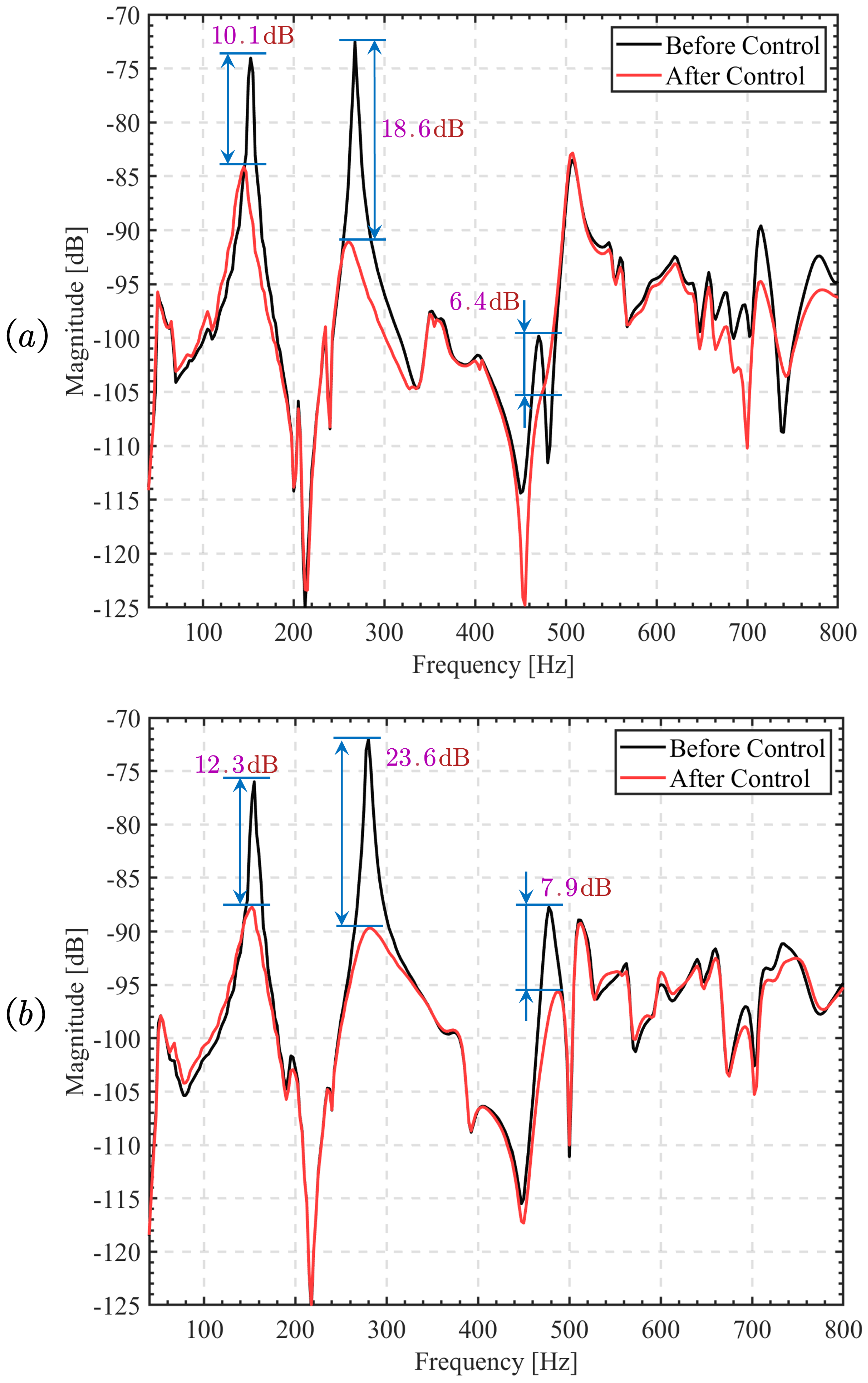
Figure 11 demonstrates the control effect of the LBIA by illustrating the vibration energy of the system before and after implementing the control measures. Both the contact sensor and the non-contact sensor, utilizing negative velocity feedback, are employed in these measures. The LBIA significantly reduces vibration energy in the first and second modes, with reductions of 10.1 dB and 18.6 dB (contact sensor), and 12.3 dB and 23.6 dB (non-contact sensor), respectively. The use of high-precision non-contact sensors, such as a laser vibrometer, has demonstrated a positive control effect, which aligns with the numerical results. However, it is important to note that the integrated sensor design of the LBIA proves effective in active control but falls short in comparison to external sensors. The disparity arises mainly due to the piezoelectric ceramic sensor’s sensitivity to the external environment, leading to interference signals that adversely affect control stability. Despite this limitation, the low cost of the sensor (about USD 0.153) makes it a promising candidate for further research and suitable for large-scale vibration control in the industry. Consequently, the following section aims to enhance the control unit’s effectiveness through multiple parallel bandpass filters.
4. Enhancing the Strain Differential Feedback Algorithm through Bandpass Filtering
4.1. Control Principle and Control Effect Simulation
To further improve the control performance of the proposed LBIA with an integrated piezoelectric sensor, the feedback control algorithm of the bandpass filter utilizes the strain differential signal (velocity signal) obtained from the LBIA with the integrated piezoelectric sensor as input. It enhances the damping of the controlled modes by employing multiple parallel bandpass filters, thereby facilitating active control of the multiple modes.
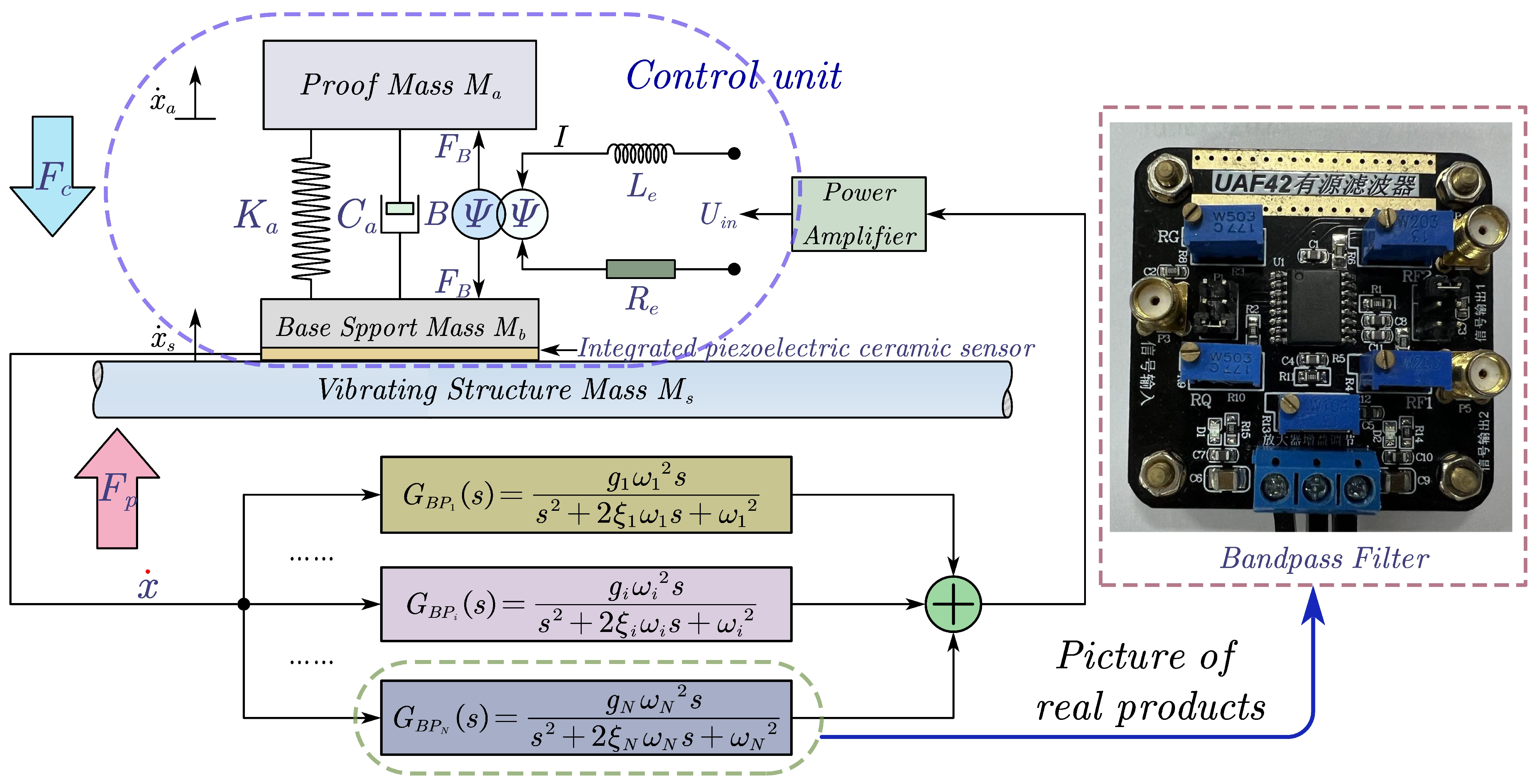
Figure 12 depicts the control principal diagram of this algorithm.
The LBIA employs an integrated piezoelectric ceramic sensor as the feedback mechanism. When the controlled structure is stimulated by
, the feedback sensor collects its vibration velocity signal. Subsequently, this signal is fed into an N-branch parallel bandpass filter, where it undergoes integration through an adder. Finally, the signal is sent to the LBIA via a power amplifier to generate the corresponding controlling force
, thus achieving closed-loop active control. Importantly, each bandpass filter’s natural frequency, damping ratio, and gain can be independently adjusted to suit specific requirements. The controller described is a parallel N-branch bandpass filter, and its output signal represents the summation of the basic velocity output from each branch bandpass filter, which can be expressed using the following Equation (
16):
where
,
, and
represent the velocity feedback gain, damping ratio, and natural frequency of the nth branch bandpass filters, respectively.
refers to the amplification gain of a power amplifier.
According to Equations (
1) and (
2), we can derive the velocity transfer function of the inertial actuator after passing through N-branches:
The velocity transfer in Equation (
17) will be utilized to assess the multimodal control effect of the proposed controller combined with LBIA with integrated piezoelectric sensor, thereby providing theoretical calculation support for subsequent experiments.
4.2. Experiment Setup and Results
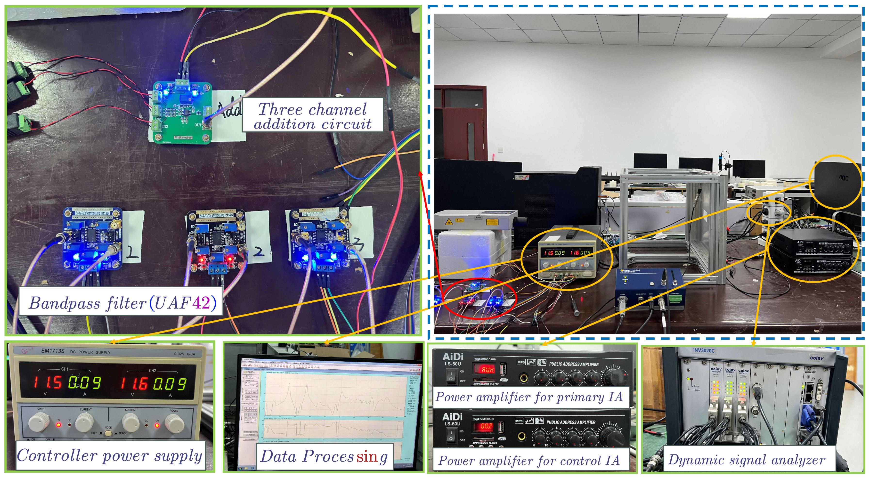
The primary objective of this experiment is to enhance the control effect of the LBIA with an integrated piezoelectric sensor by incorporating a low-cost, second-order bandpass filter, specifically designed using UAF42 (by Burr-Brown Inc., Tucson, AZ, USA).
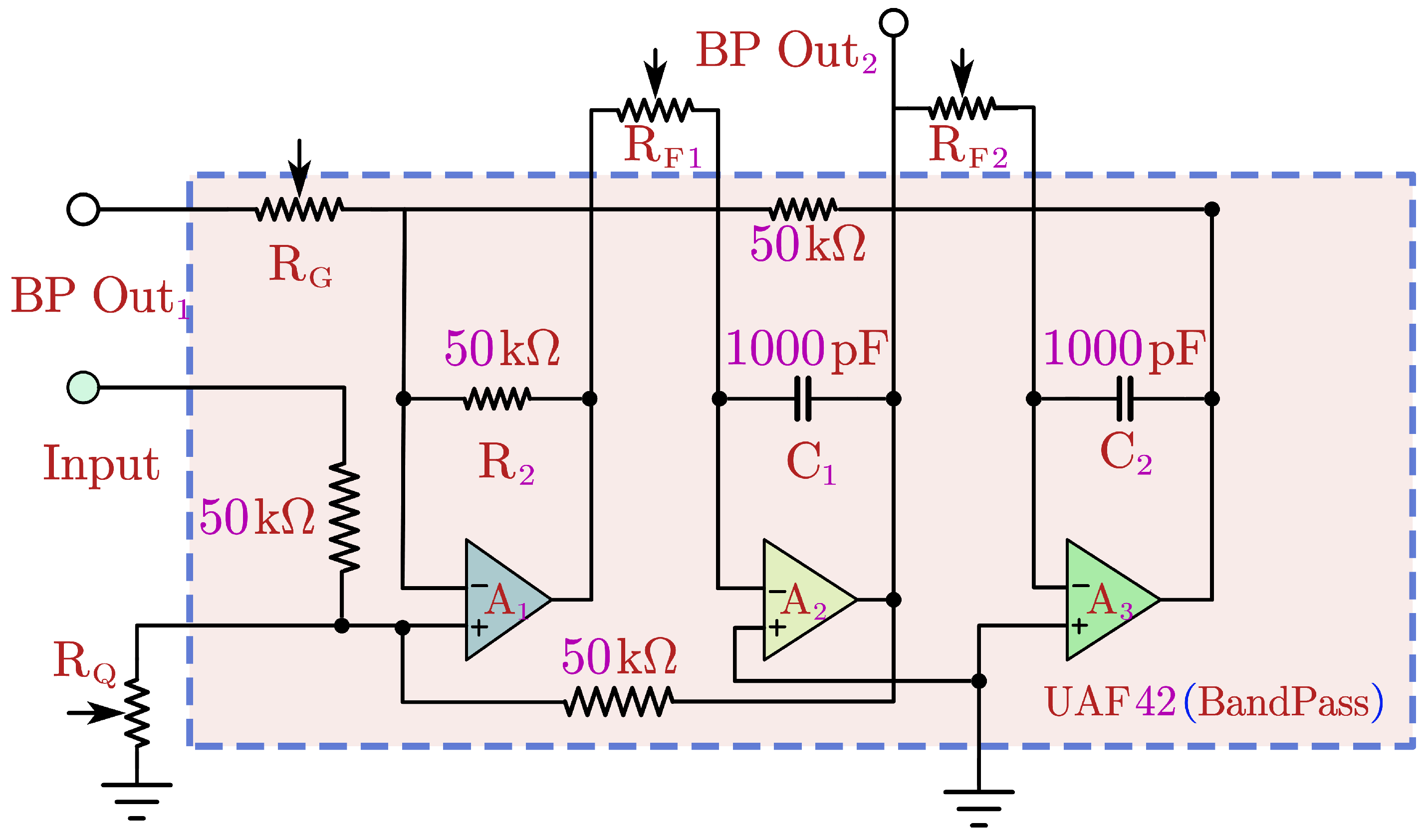
Figure 13 illustrates the schematic diagram of this specific bandpass filter.
According to
Figure 13, to facilitate the parameter adjustment in the experimental setup,
is set to a fixed value of 50
. The equation for adjusting the natural frequency, gain, and damping ratio of the bandpass filter designed based on UAF42 is derived as follows:
where
Q is the quality factor, which should be noted as inversely proportional to the passband gain. It is important to acknowledge that the
Q value and the passband gain
cannot be simultaneously maximized. When adjusting the setting, a certain balance must be achieved between the two.
After establishing the controller model, it is necessary to conduct further testing to evaluate the actual control effect of the LBIA with an integrated piezoelectric sensor combined with a bandpass filter. To accomplish this, the focus of the study is placed on a thin plate as the research object. A dedicated experimental platform is built, as illustrated in
Figure 14. This experiment serves as an extension of the previous experiments. The position arrangement is the same as in the previous experiment but different control algorithms are used.
To observe changes in the vibration energy of the controlled system, accelerometer sensors and a laser vibrometer are installed. Additionally, data acquisition and analysis software are configured for analyzing the experimental data. In this system, an integrated piezoelectric ceramic sensor is used to detect the vibration signal of the thin plate. The detected signal is then transmitted to three parallel bandpass filters. The output signals of these filters are combined using a three-way adder, and the resulting control signal is sent to the power amplifier to drive the inertial actuator for vibration suppression. This configuration forms a closed-loop control system.
Before conducting the experiment, it is essential to assess the characteristics of the multimodal controller based on multi-branch parallel features. This evaluation will pave the way for subsequent experiments. During the test, a sinusoidal signal sweeping from 0 to 800 Hz is passed through a dynamic analyzer equipped with three parallel bandpass filters.
Importantly, based on the theory and prior experiments mentioned above, the LBIA is capable of effectively controlling the first two and fourth modes from this control position. As a result, we can accurately predict the natural frequency of the bandpass filter using Equation (19). The calculated natural frequencies for the three bandpass filters are set to 156.25 Hz, 278.75 Hz, and 476.25 Hz, corresponding to the first two modes and the fourth mode of the thin plate structure. Additionally, the damping ratios for the filters are set to 0.12, 0.09, and 0.0625, respectively.
Figure 15 shows the theoretical and experimental results of the velocity transfer functions of three parallel bandpass filters.
According to
Figure 15, the theoretical calculation of the bandpass filter is basically consistent with the experimental results. However, an interesting observation was made regarding a phase jump in the bandpass filter before reaching the third natural frequency of the control. Specifically, the phase first decays to −180 degrees and then rapidly jumps to approximately +180 degrees. This phase jump is a result of the relative positions of the poles and zeros of the filter. As the signal approaches the third-order operating frequency, the phase of the poles and zeros undergoes changes, leading to the occurrence of this phase jump. Additionally, at the operating frequency, the contributions of the poles and zeros to the phase cancel each other out, resulting in a phase of 0 degrees.
It is important to note that the phase jump is a normal phenomenon and does not adversely affect the performance of the filter. Despite the jump, the phase remains close to 0 degrees at the operating frequency and does not occur within the control frequency.
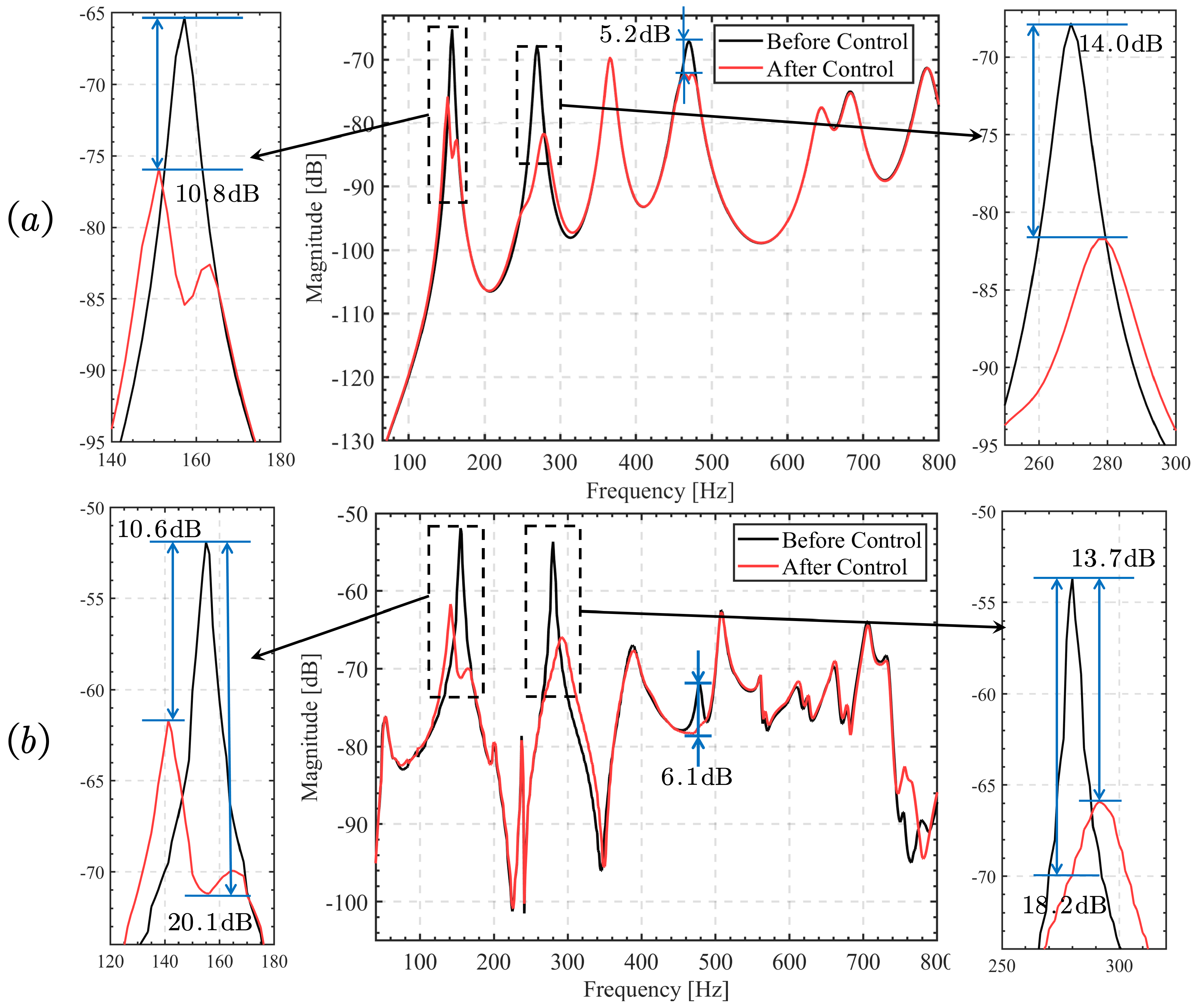
Figure 16 illustrates the calculated and experimental control performances of the LBIA with integrated piezoelectric sensor combined with three parallel bandpass filters. The experimental and calculation results demonstrate a high level of consistency. Notably,
Figure 16b presents the control effect curve of the experimental test, revealing a reduction of approximately 10.6 dB in the peak value of the first mode and around 13.7 dB in the peak value of the second mode. Furthermore, the fourth mode is entirely suppressed. Intriguingly, the first and second modes exhibit the emergence of two new modes characterized by minimal damping. This damping effect primarily arises from the utilization of the bandpass filter, which efficiently absorbs vibration energy and enhances the control effect. The experimental curve aligns closely with the numerical calculation results, effectively introducing active damping for controlling structural vibration.
Nevertheless, disparities between the experimental and numerical approaches persist, attributable to several factors. Firstly, the measurement of structural vibration incurs inherent noise. Secondly, the experimental setup exhibits a resonance shift caused by non-ideal boundary conditions, in contrast to the simulations where full clamping is assumed. Finally, the imperfect match between the filter and sensor also impacts the performance of the control system.
Despite these variations, the model accurately captures the trends in the experimental results and serves as a suitable basis for comparison, thereby showcasing its efficacy.
Figure 17 displays time domain plots of acceleration before and after applying three different control solutions, all measured using the same positions of the velocity sensor and laser vibrometer. By examining the time domain diagram obtained from the velocity sensor, a comparison of the structural vibration state can be made between various control schemes under both uncontrolled and controlled conditions. Furthermore,
Table 3 presents the percentage reduction in vibration for three control approaches.
From the observations of the percentage reduction, it can be concluded that mode II exhibits less damping than mode I, and mode I has less damping than mode IV. This pattern arises because, at this specific frequency, the inertial actuator efficiently transmits its force, leading to reduced vibration amplitudes. This mainly depends on the choice of control position and the design of the inertial actuator. Furthermore, the bandpass filter demonstrates the most effective control effect. It is capable of significantly reducing the vibration of the mode and further enhancing the control effect of the LBIA.
5. Discussion and Conclusions
This paper introduces an LBIA-integrated piezoelectric ceramic sensor control unit that serves as an inertial actuator for active vibration control. To achieve multimodal vibration control and enhance the control unit’s effectiveness, a velocity feedback controller with multiple second-order bandpass filters in parallel is also used. The main findings of this study are outlined below:
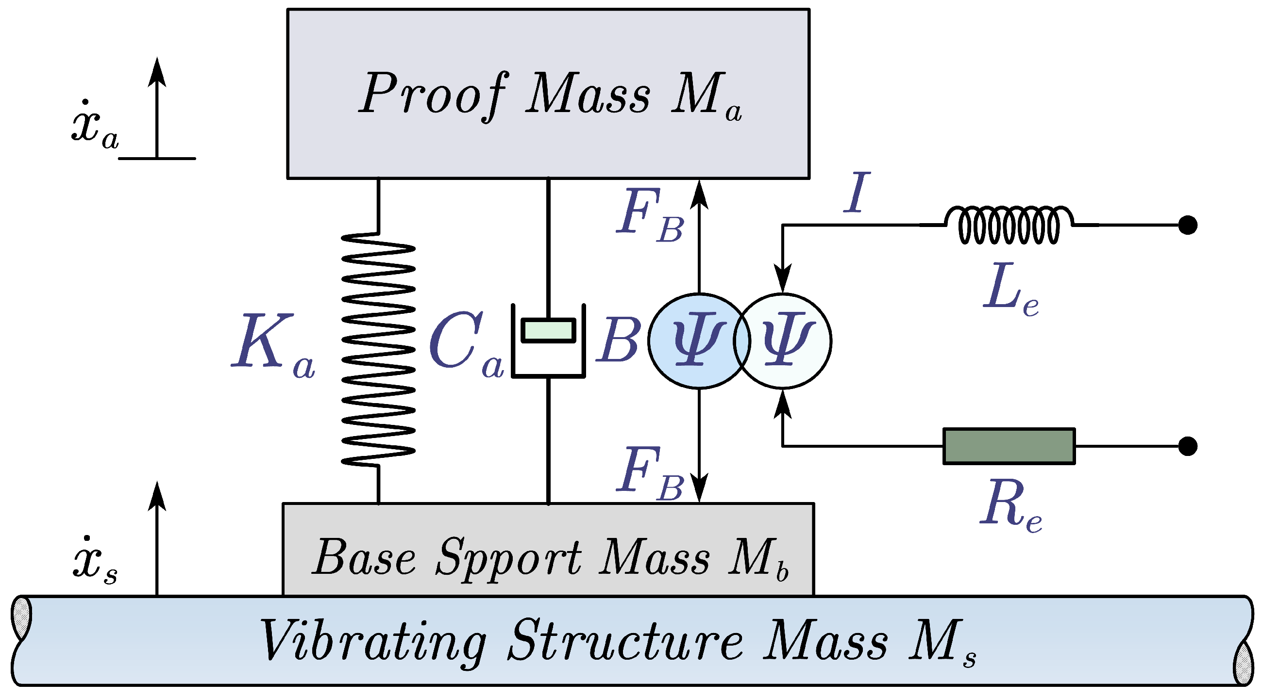
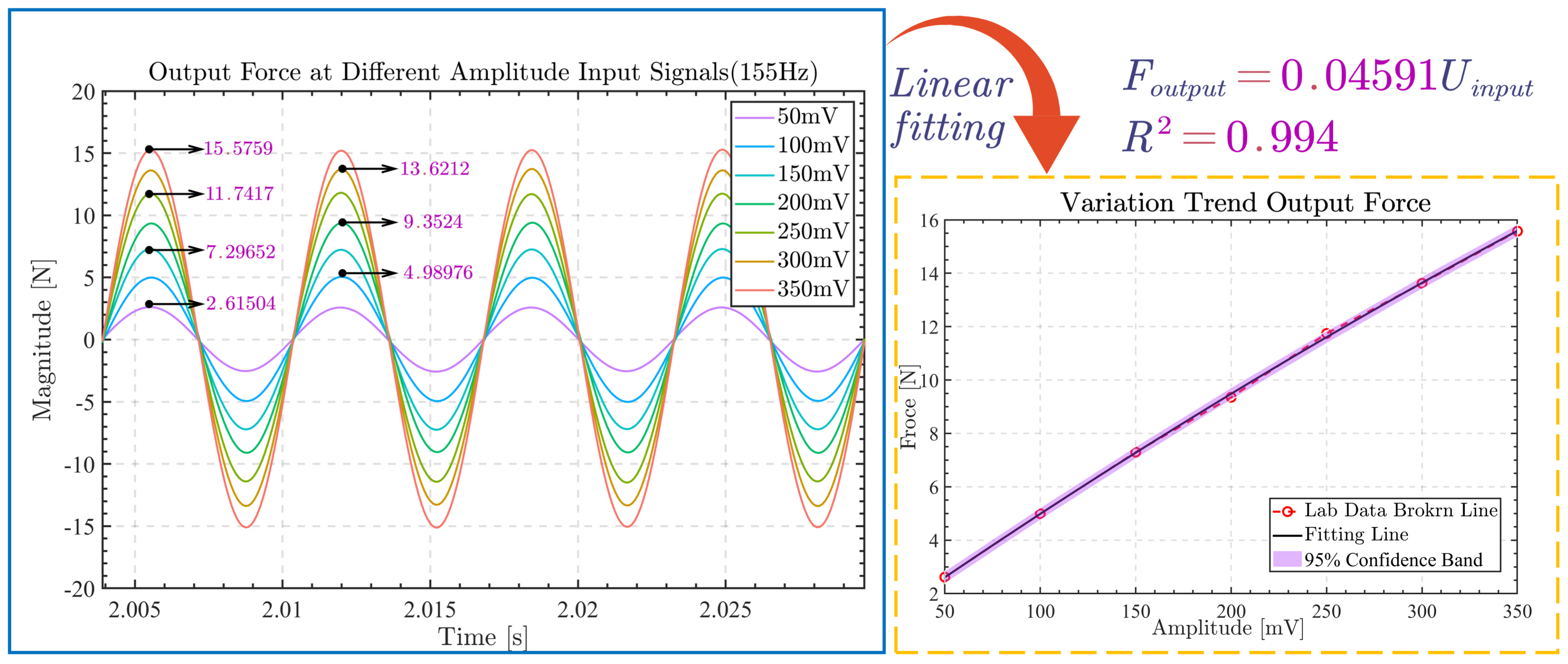
Firstly, we completed the structural design of the LBIA as an inertial actuator and established its dynamic model and impedance model. The actuator’s output characteristics and frequency response are tested on the experimental platform to verify the linear relationship between input and output, leading to the determination of the effective working frequency band.
Secondly, the integration of the piezoelectric ceramic sensor into LBIA as a separate control unit allows for establishing a mathematical model of the LBIA with piezoelectric ceramic sensor. The piezoelectric ceramic sensor converts its charge signal into a current signal through a current amplifier, resembling a differential process, which has been theoretically and experimentally proven. The resulting output current signal from the integrated sensor can be directly employed for actively controlling the vibrations of the structure. Additionally, the effectiveness of the control unit utilizing the SDF control algorithm independently for vibration control of the thin plate structure is verified through numerical calculations and experiments.
Moreover, the effectiveness of LBIA for active control of thin plate structures is experimentally verified through its traditional direct velocity negative feedback algorithm. Experimental verification is conducted using the velocity sensor and acceleration sensor on the thin plate structure. The results demonstrate the homemade inertial actuator’s effectiveness in controlling the first two modes of vibration of the thin plate structure and the fourth mode as well. The control effect is shown in
Figure 10, with the observed reductions of 12.3 dB, 23.6 dB, and 7.9 dB being consistent with the numerical calculation results, thus confirming the superiority and reliability of the control design.
It is noteworthy that the integrated design of the control unit eliminates the need for additional cumbersome alignment operations to address the control problem. The sensors are adjusted to become velocity signals that are directly usable in the control loop, avoiding the need for additional external circuitry. Furthermore, the control unit adopts a lightweight design (32.4 g) with a low cost (about USD 2.5), enabling simple operation, cost-effectiveness, compact size, and effective control of the low-frequency-band mode of structural vibration.
Moreover, to enhance the control effect of the LBIA with an integrated piezoelectric ceramic thin plate, a well-designed bandpass filter velocity negative feedback control algorithm is developed. The main advantage of the bandpass filter lies in its ability to attenuate the vibration of multiple modes simultaneously. By setting the natural frequency of the bandpass filter equal to the control frequency of the target mode, the control effect of the target mode is significantly improved. Taking the thin plate structure as an example, the performance of the proposed bandpass filter’s DVBF control is experimentally and numerically evaluated. The results show that, compared with the control unit, the control effect of the second mode is improved from 7.3 dB to 13.7 dB, with some improvement also observed in the first and second modes. The homemade inertial actuator effectively responds to the control signal processed by the filter and suppresses the vibration of the thin plate. The fourth-order natural frequency, as defined in this paper, may result from external noise; it can be conceptualized as a “non-resonant” frequency. Notably, it can be effectively regulated using a specifically designed bandpass filter to attenuate vibrations stemming from local responses. Consequently, this technique can be extended to address structural vibrations in diverse multiphysical environments, making it a promising direction for future research.
In summary, the LBIA with an integrated piezoelectric ceramic sensor, combined with the bandpass filter DVBF control algorithm proposed in this study, demonstrates remarkable results in multimodal vibration control. The lightweight design and low cost of the control unit provide valuable insights for its industrial application. Future research directions will include parameter optimization of the current method and its application to more complex structures, enabling wider applications of bandpass filters in multimodal control.


