Article

An Origami-Inspired Negative Pressure Folding Actuator Coupling Hardness with Softness

1
Ministry of Education Key Laboratory of Measurement and Control of CSE, Southeast University, Nanjing 210096, China
2
School of Mechanical and Aerospace Engineering, Nanyang Technological University, Singapore 639798, Singapore
*
Author to whom correspondence should be addressed.
Actuators 2023, 12(1), 35; https://doi.org/10.3390/act12010035
Submission received: 30 November 2022 / Revised: 2 January 2023 / Accepted: 4 January 2023 / Published: 10 January 2023
(This article belongs to the Special Issue Soft Actuators and Robotics)

Abstract

:
Soft actuators have a high potential for the creative design of flexible robots and safe human–robot interaction. So far, significant progress has been made in soft actuators’ flexibility, deformation amplitude, and variable stiffness. However, there are still deficiencies in output force and force retention. This paper presents a new negative pressure-driven folding flexible actuator inspired by origami. First, we establish a theoretical model to predict such an actuator’s output force and displacement under given pressures. Next, five actuators are fabricated using three different materials and evaluated on a test platform. The test results reveal that one actuator generates a maximum pull force of 1125.9 N and the maximum push force of 818.2 N, and another outputs a full force reaching 600 times its weight. Finally, demonstrative experiments are conducted extensively, including stretching, contracting, clamping, single-arm power assistance, and underwater movement. They show our actuators’ performance and feature coupling hardness with softness, e.g., large force output, strong force retention, two-way working, and even muscle-like explosive strength gaining. The existing soft actuators desire these valuable properties.

1. Introduction

Rigid robots are difficult to meet the increasing requirements for flexible operation due to their inherent deficiencies in flexibility and adaptability. In the past decade, people continuously studied a variety of soft robots composed of flexible materials. They have natural flexibility and adaptability for flexible operations. Therefore, soft actuators have attracted more attention as power components for developing soft robots.
A wide variety of soft actuation systems have been reported in the literature, e.g., cable-driven, fluid-driven, shape memory materials (SMMs), electroactive polymers (EAPs), and magneto- and electro-rheological materials (M/E-RMs) [1,2,3]. A cable-driven actuation system powers a soft robot by pulling a cable fixed on the robot’s main body with the help of a motor [4,5,6,7]. This method can offer low inertia, fast response, and high output force according to the selected motor. SMMs can plastically deform into temporary shapes and recover the original shapes using thermal stimulation. The cycle can always be repeated. SMMs can be divided into two categories: shape memory alloys (SMAs) [8,9,10,11] and shape memory polymers (SMPs) [12]. The materials switch back and forth between two temperatures, so the operating frequency of such an actuation manner is low. When an electric field is applied, the EAP shows a change in size or shape, resulting in actuation. Two EAPs are used in the field of soft robots, i.e., dielectric elastomer actuators (DEAs) [13,14,15,16] and ionic polymer metal composites (IPMCs) [17,18,19,20,21,22]. DEA has a high response frequency but requires a high voltage, generally greater than 1kV. IPMC works under low voltage, but the output force is small. A M/E-RM actuation system embedded with electric or magnetic particles requires an external electric or magnetic field to work. M/E-RM, including magnetorheological materials (MRM) [23,24,25,26] and electrorheological materials (ERM) [27], is suitable for making soft microactuators.
Compared with the above soft actuators, fluid-driven ones have prominent superiorities in deformation amplitude and output force [28,29]. Therefore, they have been the research focus in recent years. Some researchers use hyperelastic materials, such as silica gel or foam, to make soft actuators [30,31,32,33,34,35,36,37]. These actuators work via the cumulative deformation caused by the expansion of silica gel material under positive pressure. The maximum output force they can produce is about 1.2~15.2N and primarily be used to produce large deformation.
On the other hand, some studies reinforce soft actuators by adding fibers to silica gel materials [38,39,40]. The maximum output force of these actuators can be up to 25~40 N. However, it limits, to a great extent, the actuator’s deformation range. In addition, some soft actuators are made of fiber materials [41,42,43,44,45,46,47]. Their maximum output force is about 45~320 N. Compared with actuators based on hyperelastic materials, such actuators can bear more significant pressure and produce greater output force, but their deformation amplitude is much smaller. Further, to achieve a greater output force, some work uses rigid folding skeletons sealed with a tough impermeable film to form soft actuators [48,49,50,51,52]. As a result, the output force generated can reach 90~630 N, but the skeletons severely limit their deformation range.
The fluid-driven soft actuators mentioned above, regardless of material and structure, almost have a common feature, i.e., the output force decreases significantly with the increase of displacement. Therefore, it leads to poor force retention during work. Specifically, their output force is maximal at the initial position and decays rapidly with increasing displacement under constant pressure. Therefore, it may result in accidental situations, such as state instability and damage.
Some studies improve the retention ability of soft actuators with variable stiffness during work [53,54,55,56,57,58,59]. However, variable stiffness can only maintain some specific positions statically. At the same time, variable stiffness may restrict the actuator’s motion capability and output force.
In summary, substantial progress has been made in promoting the output force of soft actuators, but their force retention is still far from enough. However, soft actuators must have either a large output force or strong force retention for some flexible operations.
In this paper, we propose a new soft actuator paradigm with a folding skeleton and a sealed skin. Sealed by a soft film, it can be driven by negative pressure air or liquid and work in two ways. Furthermore, its output force increases significantly with the increase of displacement and can reach infinity in theory.
The main contributions of this work are as follows.
(1) Inspired by origami, we propose a novel two-way stretching flexible actuator structure coupling hardness with softness. The negative-pressure fluid-driven actuator has strong force retention and large output force simultaneously. Additionally, it can produce explosive force as human muscles do. We fabricate five actuators with a patched, 3D-printed, or machined skeleton. The test results reveal that one generates a maximum pull force of 1125.9 N and the maximum push force of 818.2 N, and another’s full output force reaches 600 times its weight.
(2) We conduct several innovative demonstrations of the actuators, including stretching, contracting, clamping, single-arm power assistance, and underwater movement. They show our actuators’ characteristics of a large output force, strong force retention, two-way working, and even generating explosive force as human muscles do. The existing soft actuators desire these valuable properties. In addition, the demonstrations indicate the excellent application potential of our flexible actuators.
The rest of this paper is organized as follows. In Section 2, materials and methods are introduced, including the working principle, structural design and mechanical analysis, and fabrication of our actuators. In Section 3, extensive experiments are conducted, and the results are analyzed and discussed. Finally, the main conclusions are drawn, and future work is planned in Section 4.

2. Materials and Methods

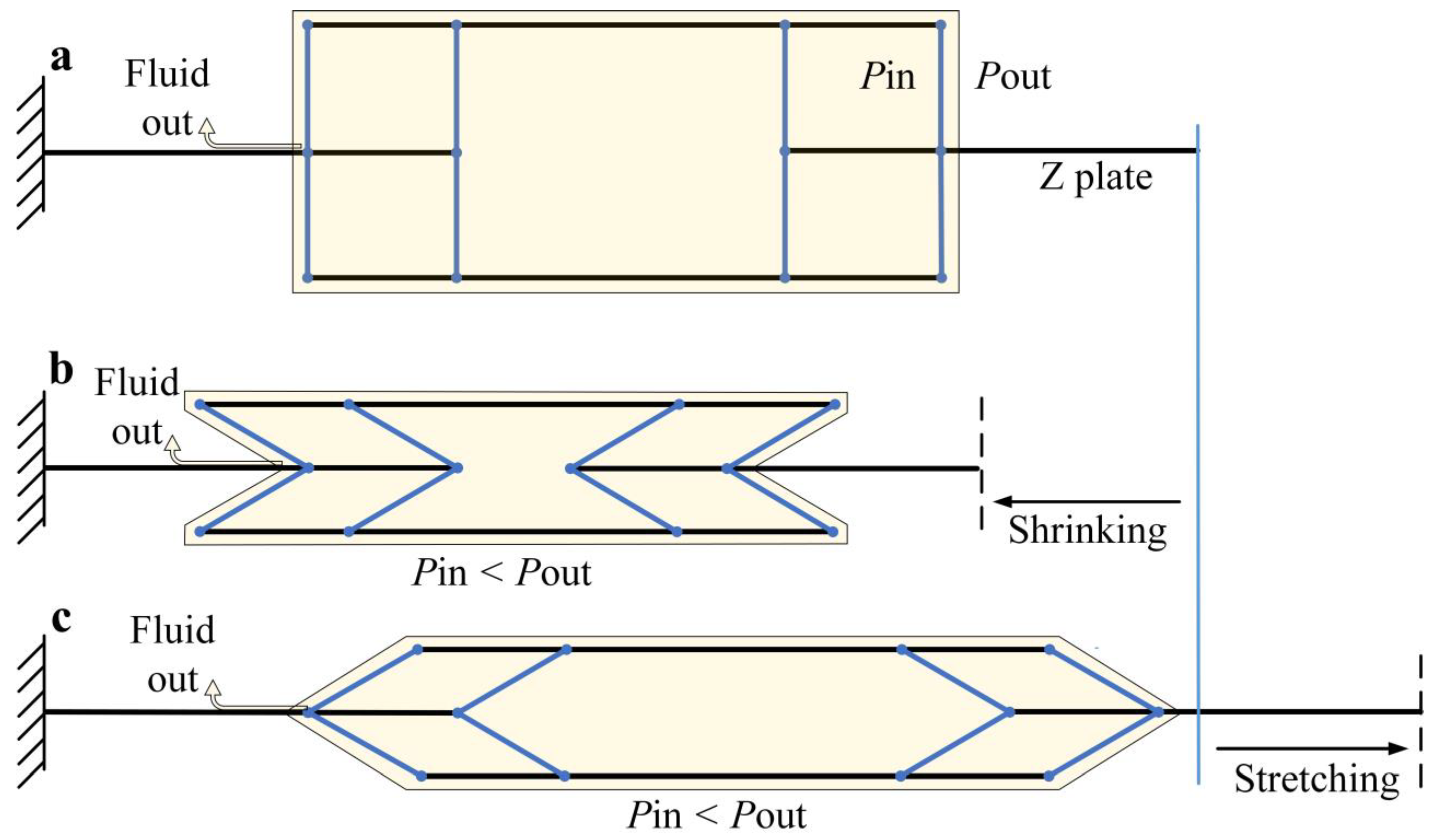
2.1. Working Principle

We propose a folding structure, as shown in Figure 1a. It comprises many vertical and horizontal plates connected by a hard or soft hinge. The rotation of a vertical plate can drive the sliding of the horizontal plate. We lay out multiple vertical plates symmetrically and enhance the movement effect through the synergy of the plates.
To form an airtight flexible actuator, we seal this structure with a soft film and drive it through negative pressure. The state evolvement of this actuator under negative pressure fluid is illustrated in Figure 1. Under negative pressure, the actuator can work in two ways, i.e., shrinking and stretching. They depend on the actuator’s initial state, which is decided by the angle between the vertical and horizontal plates. The actuator’s stretching generates a push force, and shrinking produces a pull force, as shown in Figure 1b,c.
Note that because the actuator’s deformation mode depends on its initial state determined by external forces, it cannot work simultaneously as an extendable and retractable actuator.

2.2. Structural Design and Mechanical Analysis

The initial 3D folding structure is rendered as illustrated in Figure 2a. When an actuator of this structure works under negative pressure, the soft film greatly concaves to the inside. As a result, it significantly reduces the output force of the actuator. To minimize such a negative impact, we add side supports to the structure, as shown in Figure 2b.
The forces on an actuator with the improved skeleton driven by negative pressure are shown in Figure 3a–d, including F N 2 on the side support, F N 1 , F N 2 r , F N 3 , F N 4 , and F A on the mainframe when shrinking or stretching. L 1 and L 4 represent the length of each vertical and horizontal plate, respectively. L 2 represents the distance between the rotating shafts at both ends of the beam, and L b represents the length of the beam itself. Symbol h represents the width of each vertical plate and horizontal plate of the skeleton, and L 3 is the width of the side supporting structure. Additionally, d 0 denotes the center distance of two adjacent hinges on both sides of plate Z, and L 0 is the distance between the outer edge of the upper plate and the axis of the adjacent hinge.
We assume that the flexible film is well-sealed, and its deformation has a negligible effect on the skeleton. The beam’s position in the actuator is shown in Figure 3b,c. In the skeleton, the stiffness of the beam is relatively insufficient, and elastic deformation is more likely to occur. Therefore, we first analyze the deformation of the beam, as shown in Figure 3d.
We assume that (1) we only consider the elastic deformation of the beam and treat other parts in the skeleton as rigid bodies, (2) the beam bends without changing its length, and (3) the beam is in a static equilibrium state after deformation and regarded as a rigid body.
As shown in Figure 3d, the beam deforms and maintains balance under the combined action of load concentration q and the connecting structures at both ends. The load concentration q is determined by the pressure p and the beam’s width h , that is,
q = p h
Since the beam’s deformation in length is not considered, the load at both ends is equivalent to a fixed support and movable support, as shown in Figure 3d.
The bending moment equation of the beam’s section at position x is,
M z ( x ) = 1 2 q L b x 1 2 q x 2
The approximate differential equation of the deflection curve of the beam is,
d 2 v d x 2 = M z ( x ) E I z
where E is the material’s elastic modulus, I z is the inertia moment of the beam, and E I z is the bending stiffness of the beam. v is the deflection of the beam at position x , and α is the corner of the section at position x .
In the case of small deformation, the relation between the angle α of the beam and the deflection v is,
α t a n α = d v d x
According to Equations (2) and (3), we can have the following equation.
E I z d 2 v d x 2 = M z ( x ) = 1 2 q x 2 + 1 2 q L b x
We integrate the two sides of Equation (5) two times into:
E I z α =   M z ( x ) d x = 1 6 q x 3 + 1 4 q L b x 2 + C
E I z v =   [   M z ( x ) d x ] d x = 1 24 q x 4 + 1 12 q L b x 3 + C x + D
where C and D are constants.
The boundary conditions of the left endpoint A and the middle point of the beam are, respectively,
α | x = L b 2 = 0
v | x = 0 = 0
We substitute Equations (8) and (9) into Equations (6) and (7), respectively, and obtain the following results,
C = 1 24 q L b 3
D = 0
Therefore,
α = 1 E I z ( 1 6 q x 3 + 1 4 q L b x 2 + 1 24 q L b 3 )
v = 1 E I z ( 1 24 q x 4 + 1 12 q L b x 3 + 1 24 q L b 3 x )
According to Equation (12), we can obtain the following maximum bending angle of the beam,
α m a x = α | x = 0 = α | x = L b = 1 24 q L b 3
From Equation (14), we can find that the beam’s bending deformation is mainly related to the pressure p . The greater the pressure p , the greater the bending amplitude.
The beam after deformation is an approximately circular arc. Therefore, the linear distance between A and B at both ends of the beam after deformation is,
L b = sin α m a x α m a x L b
There is a similar beam in the side support structure, its deformation is also consistent with those of the upper beam.
Then, we calculate the equivalent concentrated forces on every plate on the skeleton. Pressure differences between the actuator’s inside and outside cause them. The equivalent concentrated force of the uniformly distributed load on different plates on the skeleton is given by,
F N 1 = p S N 1 p h ( L b L b )
F N 2 = p S N 2 p L 3 ( L b L b )
F N i = p S N i ,   i = 3 ,   4
where S N 1 is the area of an upper plate or lower plate, S N 2 is the area of a single plate on the side support, S N 3 is the area of a vertical plate, and S N 4 is the equivalent area of the uniformly distributed load on the single Z plate. F N 1 , F N 2 , F N 3 , and F N 4 are the equivalent concentrated forces of the uniformly distributed loads on the above plates, as shown in Figure 3.
According to Figure 3a, we convert F N 2 on the side into its equivalent concentrated force F N 2 r on the mainframe as follows,
F N 2 r = F N 2 μ sin 2 β cos β
In Equation (18), μ is the coefficient of the arm of force F N 2 r in the above conversion, and its value is determined by the size of the side supporting structure, as shown in Table 1. β is half of the angle between two adjacent side supporting plates, as shown in Figure 3a. θ is the angle between the vertical plate and the Z plate, as shown in Figure 3b,c. The relationship between angles θ and β can be denoted by,
β = arcsin d 0 + 2 L 0 + 2 L 1 sin θ 2 L 3
Therefore, the total equivalent force on either the upper or lower plate on the skeleton is,
F N = F N 1 + F N 2 r
Assume that the direction of the output force is positive when the actuator folds. Then, according to the force analysis shown in Figure 3b,c, force F t generated by the unilateral skeleton can be calculated by,
F t = 1 2 ( F N 1 + F N 2 r ) cos θ 1 2 F N 3 sin θ + F N 3 sin θ
Thus, we have the total force F A generated by the pressure difference between the inner and outer sides of the skeleton,
F A = 2 F t + F N 4
Further, by substituting Equations (1) and (14)–(22) into Equation (23), we can obtain the following result,
F A = ( F N 1 + F N 2 r ) cos θ F N 3 sin θ + 2 F N 3 sin θ + F N 4 = p [ ( S N 1 h ( L b L b ) + [ S N 2 L 3 ( L b L b ) ] μ sin 2 β cos β ) cos θ S N 3 sin θ + 2 S N 3 sin θ + S N 4 ]
By Equation (24), the output force of the actuator has a nearly linear relationship with the pressure difference p between its inner and outer sides. In contrast, it has a nonlinear relationship with angle θ . As the actuator shrinks, the angle θ gradually decreases while the output force gradually increases. When the actuator shrinks to the limit position, θ approaches zero and the output force of the actuator tends to infinity. Similarly, when the actuator is in the extended state, the angle θ gradually increases while the output force gradually increases, and its maximum output force tends to infinity.
We consider the initial state of the actuator is when the vertical plate is perpendicular to the horizontal plate, or θ = 90 o . Assume that the direction of the displacement S is positive when the actuator folds, as shown in Figure 3b.
The initial distance between endpoints O1 and O4 on Z plates at the left and right sides of the skeleton is,
D o = L 2 + 2 L 4
During the action of the actuator, the beam bends, and the linear distance L b between its two endpoints, A and B, becomes L b . Correspondingly, the linear distance L 2 between the rotating shafts at both ends of the beam turns into L 2 . Then, we have,
L 2 L 2 = L b L b
Therefore, the distance between endpoints O1 and O4 is,
D = L 2 + 2 L 4 2 L 1 cos θ
The displacement S of the actuator can be expressed as,
S = D o D = α max sin α m a x α m a x L b + 2 L 1 cos θ
By substituting Equations (1) and (14) into Equation (28), we obtain the displacement S .
S = 1 24 p h L b 3 sin ( 1 24 p h L b 3 ) 1 24 p h L b 3 L b + 2 L 1 cos θ
By Equation (29), the actuator’s displacement is mainly related to θ . Specifically,   0 o < θ < 90 o if the actuator contracts and S increases as θ decreases. If the actuator elongates, 90 o < θ < 180 o and S increases as θ increases.
The limit displacement of the actuator is two times of L 1 , no matter whether it is retracted or extended, namely,
S m a x = 2 L 1

2.3. Fabrication of Actuator Prototypes

An actuator’s performance and features are determined mainly by its material and fabrication process. Different actuators can be used for different purposes. We fabricate five actuators using several common manufacturing processes and materials. Each has a rigid skeleton supporting the actuator and conducting force output. The patched, machined, or 3D-printed skeleton is sealed by an airtight soft film with good toughness to form a sealed cavity.

2.3.1. Patched Actuator

The fabrication process of the actuator with a patched skeleton is shown in Figure 4. We use a 0.5 mm thick white canvas as the soft substrate.
First, we paste several 0.5 mm thick polyethylene terephthalate (PET) patches and 0.6 mm thick carbon fiber plate (CFP) patches onto the canvas’ two sides’ specific positions using glue. Then, we get a combination through cutting, folding, pasting, etc., as shown in Figure 4a.
Next, we obtain the skeleton through subsequent operations, as shown in Figure 4b.
Finally, the skeleton is sealed with a 0.1 mm thick thermoplastic polyurethane (TPU) film to form an actuator, shown in Figure 4c.
The actuator we made with the above method is shown in Figure 5a. The weight of this actuator is 76.5 g, and the overall size is 220 × 68 × 52 mm, and its basic dimension parameters are in Table 1.

2.3.2. Machined Actuator

Considering that the patched actuator’s fabrication process is too cumbersome and overall rigidity is insufficient, we use aluminum alloy to make the skeleton. Specifically, we machine the individual aluminum alloy plates and assemble them into a skeleton. Then, we seal the skeleton with a 0.1 mm thick TPU film and obtain an actuator, shown in Figure 5b. Its weight is 462 g, its total size is 240 × 78 × 78 mm, and its dimensional parameters are listed in Table 1 as well.

2.3.3. 3D Printed Actuator

3D printing technology can significantly promote the development of soft actuators [1]. We adopt 3D printing to make the skeleton to reduce the fabrication cost. This skeleton is assembled from 3D-printed parts with elastic beams. The size and stiffness of the skeleton are adjustable by altering the size and material of the elastic beam. It results in actuators of different performances.
First, we use a 3D printer to print the skeleton plates and a laser cutting machine to cut carbon fiber plates and PET sheets to obtain elastic beams. Second, we assemble the resultant parts to make up three skeletons and seal each with a 0.1 mm thick TPU film to form three actuators, as shown in Figure 5. The weight of the actuators with a CFP beam and a PET beam is 242 g and 240 g, respectively. The sizes of the actuators with a 3D-printed skeleton are the same as those with a machined skeleton. Finally, to reflect the influence of the side support on the actuator’s performance, we fabricate an actuator without side supporting structures, as shown in Figure 5e. Its size is the same as the actuator with side support.
The working principle diagram in Figure 1 only shows the actuator’s main motion structure. However, it is not enough for an actuator. To fabricate an effective actuator, we must add a side support structure to back the main structure, as shown in Figure 5.

3. Results and Discussion

3.1. Experimental Setup

We designed a test platform to test the flexible actuators and evaluate their performance, as shown in Figure 6. One end of an actuator is connected to a tension-compression sensor to measure an actuator’s output force. Another end links to an electric push rod to control the actuator’s stretching. Moreover, a displacement sensor is mounted to measure the actuator’s displacement. The pressure of an actuator is derived from a vacuum pump with an air-vacuum proportional valve and a solenoid valve.
The main components of the test platform include a pull rope displacement sensor MPS-S-1000 mm from Shenzhen Milont Technology Co., LTD, Shenzhen, China, a tension-compression sensor LLBLS-I from Shanghai Longlvdianzi Technology Co., Ltd., Shanghai, China, a vacuum manometer ZSE30AF-01-E, an air-vacuum proportional valve ITV0090-3BL, solenoid valve VEX3121-025DZ-FN, and pressure reducing valve AW20-01BG-A from SMC, Tokyo, Japan, a vacuum pump 550D, from Taizhou Fujiwara Tools Co., Ltd, Taizhou, China.

3.2. Performance Test

3.2.1. Test Results and Analysis

The test results of the actuators are shown in Figure 7, Figure 8, Figure 9, Figure 10 and Figure 11, and the test statistics are listed in Table 2, Table 3, Table 4 and Table 5, respectively. To evaluate the performance of the models, Mean Absolute Error (MAE) and Mean Absolute Percentage Error (MAPE) are used as statistical means.
As shown in Figure 7a, Figure 8a and Figure 9a, the output force of the actuator with a patched skeleton, the actuator with a machined skeleton, and the PET-beamed actuator with a 3D-printed skeleton is slightly less than the force predicted by their theoretical model. The reason may be that the soft films are trapped into the skeleton due to pressure difference and offsets that are part of the output force of the skeletons. As shown in Figure 10a, the output force of the CFP-beamed actuator with a 3D-printed skeleton is slightly less than the predicted value obtained by the theoretical model in the first half of the moving process. It is mainly affected by the soft film. The output force of the second half of the moving process is slightly greater than the theoretical model’s predicted value due to the slight bending of the elastic beam to the inside.
As shown in Figure 7a, Figure 8a, Figure 9a and Figure 10a, the overall shapes of the output force curves of each actuator are almost consistent with their theoretical curves. Under constant pressure, the output force of the actuators increases gradually with the arising displacement, and the growth is faster and faster. By the experimental results, as the pressure difference increases, the deviation between the output force and the model-predicted value gradually increases with the film shrinking towards the skeleton inside. In addition, we observed an approximately linear relationship between the output force of the actuator and the pressure at a given displacement, as shown in Figure 7b, Figure 8b, Figure 9b and Figure 10b. Again, it is consistent with the prediction of the theoretical model established in Section 2.2.
The flexible substrate between two adjacent hard patches acts as a rotating shaft in the patched skeleton. Nevertheless, the rotating shaft can remain stable only when the flexible substrate is under tension. Therefore, the actuator with a patched skeleton can only work effectively in contraction. In the experiment, the actuator can produce a pull force of 450 N under pressure 45 kPa, equivalent to 600 times the actuator’s gravity. Meanwhile, the skeleton has undergone a large deformation, and continuing to increase the pressure leads to damage to the actuator.
The actuator with a machined skeleton can bear the force in all directions and work during elongation and contraction. When the pressure is 48.5 kPa, the actuator can generate a pull force of 1125.9 N, 248.5 times its gravity, and a thrust force of 818.2 N, 180.6 times its gravity, as given in Table 3. Considering the experimental safety, we do not further test whether its mechanical properties provided higher pressure. Equation (24) and Figure 7b, Figure 8b, Figure 9b and Figure 10b show an approximately linear relationship between the actuator’s output force and the given pressure. The maximum vacuum pressure in the air can reach about -101kPa. Therefore, the tests can only examine about half of the potential of the actuator.
The actuators with a 3D-printed skeleton can transmit the force through the elastic beam. Therefore, its mechanical performances depend on the stiffness of the elastic beam to a certain extent. The stiffness of the PET beam is relatively minor, making it challenging to bear push force in the length direction. Thus, the actuator with a PET-beamed 3D-printed skeleton can produce a greater pull force but a relatively smaller push force. By testing, the PET-beamed actuator can reach a maximum pull force of 595.6 N, 253.4 times its gravity, but the full thrust generated is only 79N. In contrast, although the stiffness of the CFP beam is relatively higher, the tension generated by the actuator with a CFP-beamed 3D-printed skeleton is far greater than the thrust. Experimental tests show that it can achieve a maximum pull force of 759.4 N, 320.4 times its gravity, but the full thrust generated is only 60 N.
There is a particular gap at each joint of the skeleton in all the actuators mentioned above. It leads to a certain motion redundancy. Under the pressure difference between the inner and outer sides, the actuators can stabilize the state by mutual restriction between the skeleton components. The experimental results show that increasing the skeleton’s overall stiffness or the actuator’s motion amplitude can improve the actuator’s structural stability. In addition, as the pressure difference between the inner and outer sides increases, the structural stability of the actuator is depressed.

3.2.2. Performance Comparison among Different Actuators

To explore the effect of side support on the performance of an actuator, we compare the CFP-beamed actuator with a 3D-printed skeleton and the actuator without side support. As shown in Figure 11a, the output force of the former is significantly greater than that of the latter concerning the same displacement under a certain pressure. Thus, the side support dramatically improves the output force of an actuator. On the other hand, the side support increases the internal restriction in a skeleton and significantly enhances the morphological stability of an actuator.
Similarly, we compared the PET-beamed actuator and the CFP-beamed actuator to examine the influence of the skeleton’s stiffness on the actuator’s performance. Both have a 3D-printed skeleton. As shown in Figure 11b, the output force of the former actuator is significantly greater than that of the latter regarding the same displacement under a given pressure. Note that the PET beam is more apt to dent into the inner of the skeleton than the CFP beam. It significantly reduces the effective stroke of the PET-beamed actuator. Therefore, with the same displacement and given pressure, the greater the skeleton’s stiffness, the greater the actuator’s output force, and the higher the actuator’s effective stroke.
On the other hand, actuators made of different materials have different mechanical properties. For example, as shown in Figure 11c, the greater the skeleton’s stiffness, the greater the full output force of an actuator under specific pressure.
Note that the stiffness of the PET beam is small, and excessive elastic deformation occurs when the pressure is too large, which significantly reduces the effective area of external pressure and the output force. Therefore, in Figure 11c, once the pressure exceeds 30 kPa, the maximum output force of the actuator with a PET beam decreases.

3.3. Demonstration of Actuators

Our flexible actuators have some characteristics unexplored before in the current work. These characteristics include dual-mode work, high force retention, large output force, and some explosiveness. To illustrate them, we design four demonstrations, i.e., push and pull, clamping, single-arm-assisted motion, and motion in water.
Figure 12a–d illustrates two work modes of our actuators, i.e., push and pull in horizontal and vertical directions.
First, the CFP-beamed actuator with a 3D-printed skeleton can push and pull an 8.1 kg concrete block horizontally. In the beginning, the actuator in the push mode cannot move the concrete block away. However, once the pressure increases to 45 kPa, the actuator shoves the concrete block 4 cm away instantaneously while it stretches only 2 cm on its own, as shown in Figure 12a and Movie S1. Then, when the actuator works in the pull mode, it can pull the concrete block back 2 cm under the same pressure, as shown in Figure 12b and Movie S2.
Next, the actuator with a machined skeleton working in the pull mode can stretch a spring with an elastic coefficient of 3 N/mm for 15 mm under the pressure of 12 kPa, as shown in Figure 12c and Movie S3. Besides, the actuator in push mode can break a pencil under the pressure of 25 kPa, as shown in Figure 12d and Movie S4.
Our actuator with a machined skeleton can produce a vast output force. As demonstrated in Figure 12e and Movie S5, the actuator lifts the rebars of 60.5 kg instantly for about 7 mm without assistance when the driving pressure is 60 kPa. The characteristics of the actuator, which can quickly generate a considerable output force in a short time, are similar to the explosive force of biological muscles. It confirms again that our actuators have some explosive force like human muscles [60,61]. The actuator’s lifting status remains unchanged by keeping the same pressure. It shows that the actuator has excellent force retention.
We designed a 3D-printed clamping jaw driven by the actuator with a machined skeleton. This clamping jaw can clamp the concrete block and keep the clamping when an electric push rod lifts it and the block for 22 s, as shown in Figure 12f and Movie S6. In the above process, the clamping still holds with no signs of loosening. It shows our actuators’ high force retention again.
Additionally, we designed a power-assisted structure for a single arm using the CFP-beamed actuator with a 3D-printed skeleton, as shown in Figure 12g and Movie S7. The actuator tows a wood model’s forearm with a Bowden cable. First, the structure bends the forearm 30° from the original position. Next, we hang a 500 mL bottle of water on the wrist when the forearm turns nearly to the horizontal position. Due to the actuator’s force retention, the forearm always keeps the status as long as the actuator works.
Our actuators can be driven by liquid under negative pressure as well. For example, we use a large syringe with water to drive the PET-beamed actuator with a 3D-printed skeleton. The hydraulic actuator can pull the concrete block to slide 3 cm in water, as shown in Figure 12h and Movie S8.

4. Conclusions

We propose a novel flexible actuator structure coupling hardness with softness and fabricate five prototypes with different materials. The performance test shows that our actuators driven by negative pressure fluid can simultaneously output large force and achieve high force retention. Additionally, it can either stretch or shrink and produce human-muscle-like explosive force. The five actuators’ performances vary. The actuator with a machined skeleton can reach a full pull force of 1125.9 N and a maximum thrust force of 818.2 N. The actuator with a patched skeleton can output the maximal force 600 times its weight. We demonstrated a series of applications of our actuators, including stretching, shrinking, clamping, power assistance, and underwater movement.
Further, our actuators can be used for multiple purposes due to their excellent properties and performances.
  • They can work in air or water, driven by negative pressure fluid, air, or liquid. In addition, they are portable thanks to their folding structures.
  • They are suitable for pushing or pulling heavy loads, owing to their large output force in a small range of strokes in two ways.
  • In some scenes requiring highly reliable clamping, they can drive a robotic end effector to clamp a heavy object with high force retention. On the other hand, they can occasionally adapt well to the gradually increasing load.
  • They can also apply to scenes where explosive force is required.
  • Moreover, our actuators can also be combined in series or parallel to expand their applications.
On the other hand, our actuator also has some limitations. First, the actuator’s work mode is determined by its initial state; thus, it cannot switch the work mode automatically. Second, the actuator’s motion range is limited by the size of its skeleton’s horizontal and vertical plates. Our ongoing work is to improve our actuator and further design an actuator for bending motion.

Supplementary Materials

The following supporting information can be downloaded at: https://www.mdpi.com/article/10.3390/act12010035/s1, Movie S1: The CFP-beamed actuator pushes a concrete block; Movie S2: The CFP-beamed actuator pulls a concrete block; Movie S3: The actuator with a machined skeleton pulls a spring; Movie S4: The actuator with a machined skeleton punches a pencil; Movie S5: The actuator with a machined skeleton lifts rebars; Movie S6: A clamping gripper clamps a concrete block; Movie S7: The CFP-beamed actuator assists the model’s arm; Movie S8: The PET-beamed actuator moves in the water.

Author Contributions

Conceptualization, Z.S., W.Z. and J.L.; methodology, Z.S., W.Z., J.L. and I.-M.C.; validation, Z.S., W.Z. and Z.Z.; writing—original draft preparation, Z.S., W.Z. and Z.Z.; writing—review and editing, J.L., I.-M.C. and Z.S. All authors have read and agreed to the published version of the manuscript.

Funding

This research was funded in part by the National Key R&D Program of China (Grant No. 2021YFF0500900), National Natural Science Foundation of China (No. 61773115), and Shenzhen Fundamental Research Program (No. CYJ20190813152401690).

Institutional Review Board Statement

Not applicable.

Informed Consent Statement

Not applicable.

Data Availability Statement

Not applicable.

Conflicts of Interest

The authors declare no conflict of interest.

References

  1. Stano, G.; Percoco, G. Additive manufacturing aimed to soft robots fabrication: A review. Extreme Mech. Lett. 2021, 42, 101079. [Google Scholar] [CrossRef]
  2. Zaidi, S.; Maselli, M.; Laschi, C.; Cianchetti, M. Actuation Technologies for Soft Robot Grippers and Manipulators: A Review. Curr. Robot. Rep. 2021, 2, 355–369. [Google Scholar] [CrossRef]
  3. Pan, M.; Yuan, C.; Liang, X.; Dong, T.; Liu, T.; Zhang, J.; Zou, J.; Yang, H.; Bowen, C. Soft Actuators and Robotic Devices for Rehabilitation and Assistance. Adv. Intell. Syst. 2022, 4, 2100140. [Google Scholar] [CrossRef]
  4. Calisti, M.; Giorelli, M.; Levy, G.; Mazzolai, B.; Hochner, B.; Laschi, C.; Dario, P. An octopus-bioinspired solution to movement and manipulation for soft robots. Bioinspir. Biomim. 2011, 6, 036002. [Google Scholar] [CrossRef] [PubMed] [Green Version]
  5. Shahid, Z.; Glatman, A.L.; Ryu, S.C. Design of a Soft Composite Finger with Adjustable Joint Stiffness. Soft Robot. 2019, 6, 722–732. [Google Scholar] [CrossRef] [PubMed]
  6. Lin, N.; Wu, P.; Wang, M.; Wei, J.; Yang, F.; Xu, S.; Ye, Z.; Chen, X. IMU-Based Active Safe Control of a Variable Stiffness Soft Actuator. IEEE Robot. Autom. Lett. 2019, 4, 1247–1254. [Google Scholar] [CrossRef]
  7. Li, Y.; Chen, Y.; Ren, T.; Li, Y.; Choi, S.H. Precharged Pneumatic Soft Actuators and Their Applications to Untethered Soft Robots. Soft Robot. 2018, 5, 567–575. [Google Scholar] [CrossRef]
  8. Mazzolai, B.; Margheri, L.; Cianchetti, M.; Dario, P.; Laschi, C. Soft-robotic arm inspired by the octopus: II. From artificial requirements to innovative technological solutions. Bioinspir. Biomim. 2012, 7, 025005. [Google Scholar] [CrossRef]
  9. Cianchetti, M.; Calisti, M.; Margheri, L.; Kuba, M.; Laschi, C. Bioinspired locomotion and grasping in water: The soft eight-arm OCTOPUS robot. Bioinspir. Biomim. 2015, 10, 035003. [Google Scholar] [CrossRef] [Green Version]
  10. Yin, H.; Tian, L.; Yang, G. Design of fibre array muscle for soft finger with variable stiffness based on nylon and shape memory alloy. Adv. Robot. 2020, 34, 599–609. [Google Scholar] [CrossRef]
  11. Huang, X.; Ford, M.; Patterson, Z.J.; Zarepoor, M.; Pan, C.; Majidi, C. Shape memory materials for electrically-powered soft machines. J. Mater. Chem. B 2020, 8, 4539–4551. [Google Scholar] [CrossRef] [PubMed]
  12. Behl, M.; Kratz, K.; Zotzmann, J.; Nöchel, U.; Lendlein, A. Reversible Bidirectional Shape-Memory Polymers. Adv. Mater. 2013, 25, 4466–4469. [Google Scholar] [CrossRef] [PubMed]
  13. Youn, J.-H.; Jeong, S.M.; Hwang, G.; Kim, H.; Hyeon, K.; Park, J.; Kyung, K.-U. Dielectric Elastomer Actuator for Soft Robotics Applications and Challenges. Appl. Sci. 2020, 10, 640. [Google Scholar] [CrossRef] [Green Version]
  14. Moss, A.; Krieg, M.; Mohseni, K. Modeling and Characterizing a Fiber-Reinforced Dielectric Elastomer Tension Actuator. IEEE Robot. Autom. Lett. 2021, 6, 1264–1271. [Google Scholar] [CrossRef]
  15. Li, W.-B.; Zhang, W.-M.; Zou, H.-X.; Peng, Z.-K.; Meng, G. A Fast Rolling Soft Robot Driven by Dielectric Elastomer. IEEE/ASME Trans. Mechatron. 2018, 23, 1630–1640. [Google Scholar] [CrossRef]
  16. Liang, W.; Liu, H.; Wang, K.; Qian, Z.; Ren, L.; Ren, L. Comparative study of robotic artificial actuators and biological muscle. Adv. Mech. Eng. 2020, 12, 1687814020933409. [Google Scholar] [CrossRef]
  17. Wang, H.; Chen, J.; Lau, H.Y.K.; Ren, H. Motion Planning Based on Learning from Demonstration for Multiple-Segment Flexible Soft Robots Actuated by Electroactive Polymers. IEEE Robot. Autom. Lett. 2016, 1, 391–398. [Google Scholar] [CrossRef]
  18. Ishiki, A.; Nabae, H.; Kodaira, A.; Suzumori, K. PF-IPMC: Paper/Fabric Assisted IPMC Actuators for 3D Crafts. IEEE Robot. Autom. Lett. 2020, 5, 4035–4041. [Google Scholar] [CrossRef]
  19. Yi, X.; Chakarvarthy, A.; Chen, Z. Cooperative Collision Avoidance Control of Servo/IPMC Driven Robotic Fish with Back-Relaxation Effect. IEEE Robot. Autom. Lett. 2021, 6, 1816–1823. [Google Scholar] [CrossRef]
  20. Zhu, Z.; Bian, C.; Ru, J.; Bai, W.; Chen, H. Rapid deformation of IPMC under a high electrical pulse stimulus inspired by action potential. Smart Mater. Struct. 2019, 28, 01LT01. [Google Scholar] [CrossRef]
  21. Tang, X.; Li, H.; Ma, T.; Yang, Y.; Luo, J.; Wang, H.; Jiang, P. A Review of Soft Actuator Motion: Actuation, Design, Manufacturing and Applications. Actuators 2022, 11, 331. [Google Scholar] [CrossRef]
  22. Rich, S.I.; Wood, R.J.; Majidi, C. Untethered soft robotics. Nat. Electron. 2018, 1, 102–112. [Google Scholar] [CrossRef]
  23. Hu, W.; Lum, G.Z.; Mastrangeli, M.; Sitti, M. Small-scale soft-bodied robot with multimodal locomotion. Nature 2018, 554, 81–85. [Google Scholar] [CrossRef] [PubMed]
  24. Kim, J.; Chung, S.E.; Choi, S.-E.; Lee, H.; Kim, J.; Kwon, S. Programming magnetic anisotropy in polymeric microactuators. Nat. Mater. 2011, 10, 747–752. [Google Scholar] [CrossRef] [PubMed]
  25. Kim, Y.; Yuk, H.; Zhao, R.; Chester, S.A.; Zhao, X. Printing ferromagnetic domains for untethered fast-transforming soft materials. Nature 2018, 558, 274–279. [Google Scholar] [CrossRef]
  26. Kim, Y.; Parada, G.A.; Liu, S.; Zhao, X. Ferromagnetic soft continuum robots. Sci. Robot. 2019, 4, eaax7329. [Google Scholar] [CrossRef]
  27. Sudhawiyangkul, T.; Yoshida, K.; Eom, S.I.; Kim, J.W. A Multi-DOF Soft Microactuator Integrated with Flexible Electro-Rheological Microvalves Using an Alternating Pressure Source. Smart Mater. Struct. 2021, 30, 085006. [Google Scholar] [CrossRef]
  28. Walker, J.; Zidek, T.; Harbel, C.; Yoon, S.; Strickland, F.S.; Kumar, S.; Shin, M. Soft Robotics: A Review of Recent Developments of Pneumatic Soft Actuators. Actuators 2020, 9, 3. [Google Scholar] [CrossRef] [Green Version]
  29. Kalita, B.; Leonessa, A.; Dwivedy, S.K. A Review on the Development of Pneumatic Artificial Muscle Actuators: Force Model and Application. Actuators 2022, 11, 288. [Google Scholar] [CrossRef]
  30. Jiao, Z.; Zhuang, Z.; Cheng, Y.; Deng, X.; Sun, C.; Yu, Y.; Li, F. Lightweight Dual-Mode Soft Actuator Fabricated from Bellows and Foam Material. Actuators 2022, 11, 245. [Google Scholar] [CrossRef]
  31. Hao, Y.; Gong, Z.; Xie, Z.; Guan, S.; Yang, X.; Wang, T.; Wen, L. A Soft Bionic Gripper with Variable Effective Length. J. Bionic Eng. 2018, 15, 220–235. [Google Scholar] [CrossRef]
  32. Yan, J.; Xu, Z.; Shi, P.; Zhao, J. A Human-Inspired Soft Finger with Dual-Mode Morphing Enabled by Variable Stiffness Mechanism. Soft Robot. 2021, 9, 399–411. [Google Scholar] [CrossRef]
  33. Sparrman, B.; du Pasquier, C.; Thomsen, C.; Darbari, S.; Rustom, R.; Laucks, J.; Shea, K.; Tibbits, S. Printed silicone pneumatic actuators for soft robotics. Addit. Manuf. 2021, 40, 101860. [Google Scholar] [CrossRef]
  34. Pan, M.; Yuan, C.; Anpalagan, H.; Plummer, A.; Zou, J.; Zhang, J.; Bowen, C. Soft Controllable Carbon Fibre-Based Piezore-sistive Self-Sensing Actuators. Actuators 2020, 9, 79. [Google Scholar] [CrossRef]
  35. Bell, M.A.; Gorissen, B.; Bertoldi, K.; Weaver, J.C.; Wood, R.J. A Modular and Self-Contained Fluidic Engine for Soft Actuators. Adv. Intell. Syst. 2021, 4, 2100094. [Google Scholar] [CrossRef]
  36. Wang, B.; Guo, W.; Feng, S.; Hongdong, Y.; Wan, F.; Song, C. Volumetrically Enhanced Soft Actuator with Proprioceptive Sensing. IEEE Robot. Autom. Lett. 2021, 6, 5284–5291. [Google Scholar] [CrossRef]
  37. Ke, X.; Jang, J.; Chai, Z.; Yong, H.; Zhu, J.; Chen, H.; Guo, C.F.; Ding, H.; Wu, Z. Stiffness Preprogrammable Soft Bending Pneumatic Actuators for High-Efficient, Conformal Operation. Soft Robot. 2021, 9, 613–624. [Google Scholar] [CrossRef] [PubMed]
  38. Wirekoh, J.; Park, Y.-L. Design of flat pneumatic artificial muscles. Smart Mater. Struct. 2017, 26, 035009. [Google Scholar] [CrossRef]
  39. Wirekoh, J.; Valle, L.; Pol, N.; Park, Y.-L. Sensorized, Flat, Pneumatic Artificial Muscle Embedded with Biomimetic Microfluidic Sensors for Proprioceptive Feedback. Soft Robot. 2019, 6, 768–777. [Google Scholar] [CrossRef] [Green Version]
  40. Hu, L.; Gau, D.; Nixon, J.; Klein, M.; Fan, Y.; Menary, G.; Roche, E.T. Precurved, Fiber-Reinforced Actuators Enable Pneumatically Efficient Replication of Complex Biological Motions. Soft Robot. 2021, 9, 293–308. [Google Scholar] [CrossRef]
  41. Yang, H.D.; Greczek, B.T.; Asbeck, A.T. Modeling and Analysis of a High-Displacement Pneumatic Artificial Muscle with Integrated Sensing. Front. Robot. AI 2019, 5, 136. [Google Scholar] [CrossRef]
  42. Shaheen, R.; Doumit, M.; Helal, A. Design and characterization of a hyperelastic tubular soft composite. J. Mech. Behav. Biomed. Mater. 2017, 75, 228–235. [Google Scholar] [CrossRef] [PubMed]
  43. Al-Fahaam, H.; Davis, S.; Nefti-Meziani, S. The design and mathematical modelling of novel extensor bending pneumatic artificial muscles (EBPAMs) for soft exoskeletons. Robot. Auton. Syst. 2018, 99, 63–74. [Google Scholar] [CrossRef]
  44. Guan, Q.; Sun, J.; Liu, Y.; Wereley, N.M.; Leng, J. Novel Bending and Helical Extensile/Contractile Pneumatic Artificial Muscles Inspired by Elephant Trunk. Soft Robot. 2020, 7, 597–614. [Google Scholar] [CrossRef] [PubMed]
  45. Zhu, M.; Do, T.N.; Hawkes, E.; Visell, Y. Fluidic Fabric Muscle Sheets for Wearable and Soft Robotics. Soft Robot. 2020, 7, 179–197. [Google Scholar] [CrossRef] [Green Version]
  46. Kim, W.; Park, H.; Kim, J. Compact Flat Fabric Pneumatic Artificial Muscle (ffPAM) for Soft Wearable Robotic Devices. IEEE Robot. Autom. Lett. 2021, 6, 2603–2610. [Google Scholar] [CrossRef]
  47. Naclerio, N.D.; Hawkes, E.W. Simple, Low-Hysteresis, Foldable, Fabric Pneumatic Artificial Muscle. IEEE Robot. Autom. Lett. 2020, 5, 3406–3413. [Google Scholar] [CrossRef]
  48. Kulasekera, A.L.; Arumathanthri, R.B.; Chathuranga, D.S.; Gopura, R.; Lalitharatne, T.D. A thin-walled vacuum actuator (ThinVAc) and the development of multi-filament actuators for soft robotic applications. Sens. Actuators A Phys. 2021, 332, 113088. [Google Scholar] [CrossRef]
  49. Yu, B.; Yang, J.; Du, R.; Zhong, Y. A Versatile Pneumatic Actuator Based on Scissor Mechanisms: Design, Modeling, and Experiments. IEEE Robot. Autom. Lett. 2021, 6, 1288–1295. [Google Scholar] [CrossRef]
  50. Li, S.; Vogt, D.M.; Rus, D.; Wood, R.J. Fluid-driven origami-inspired artificial muscles. Proc. Natl. Acad. Sci. USA 2017, 114, 13132–13137. [Google Scholar] [CrossRef]
  51. Li, S.; Vogt, D.M.; Bartlett, N.W.; Rus, D.; Wood, R.J. Tension Pistons: Amplifying Piston Force Using Fluid-Induced Tension in Flexible Materials. Adv. Funct. Mater. 2019, 29, 1901419. [Google Scholar] [CrossRef]
  52. Lee, J.-G.; Rodrigue, H. Origami-Based Vacuum Pneumatic Artificial Muscles with Large Contraction Ratios. Soft Robot. 2019, 6, 109–117. [Google Scholar] [CrossRef] [PubMed]
  53. Liu, T.; Xia, H.; Lee, D.-Y.; Firouzeh, A.; Park, Y.-L.; Cho, K.-J. A Positive Pressure Jamming Based Variable Stiffness Structure and its Application on Wearable Robots. IEEE Robot. Autom. Lett. 2021, 6, 8078–8085. [Google Scholar] [CrossRef]
  54. Ranzani, T.; Gerboni, G.; Cianchetti, M.; Menciassi, A. A bioinspired soft manipulator for minimally invasive surgery. Bioinspir. Biomim. 2015, 10, 035008. [Google Scholar] [CrossRef] [PubMed]
  55. Ranzani, T.; Cianchetti, M.; Gerboni, G.; De Falco, I.; Menciassi, A. A Soft Modular Manipulator for Minimally Invasive Sur-gery: Design and Characterization of a Single Module. IEEE Trans. Robot. 2016, 32, 187–200. [Google Scholar] [CrossRef]
  56. De Falco, I.; Cianchetti, M.; Menciassi, A. A soft multi-module manipulator with variable stiffness for minimally invasive surgery. Bioinspir. Biomim. 2017, 12, 056008. [Google Scholar] [CrossRef]
  57. Li, Y.; Chen, Y.; Yang, Y.; Wei, Y. Passive Particle Jamming and Its Stiffening of Soft Robotic Grippers. IEEE Trans. Robot. 2017, 33, 446–455. [Google Scholar] [CrossRef]
  58. Yan, J.; Shi, P.; Xu, Z.; Zhao, J. A Wide-Range Stiffness-Tunable Soft Actuator Inspired by Deep-Sea Glass Sponges. Soft Robot. 2021, 9, 625–637. [Google Scholar] [CrossRef]
  59. Wang, Y.; Yang, Z.; Zhou, H.; Zhao, C.; Barimah, B.; Li, B.; Xiang, C.; Li, L.; Gou, X.; Luo, M. Inflatable Particle-Jammed Robotic Gripper Based on Integration of Positive Pressure and Partial Filling. Soft Robot. 2021, 9, 309–323. [Google Scholar] [CrossRef]
  60. Tillin, N.A.; Pain, M.T.G.; Folland, J.P. Contraction speed and type influences rapid utilisation of available muscle force: Neural and contractile mechanisms. J. Exp. Biol. 2018, 221, jeb193367. [Google Scholar] [CrossRef]
  61. Del Vecchio, A.; Negro, F.; Holobar, A.; Casolo, A.; Folland, J.P.; Felici, F.; Farina, D. You Are as Fast as Your Motor Neurons: Speed of Recruitment and Maximal Discharge of Motor Neurons Determine the Maximal Rate of Force Development in Hu-mans. J. Physiol. 2019, 597, 2445–2456. [Google Scholar] [CrossRef] [PubMed]
Figure 1. The folding structure’s state evolvement: (a) A flexible actuator in the initial state; (b) The flexible actuator is shrinking; (c) The flexible actuator in stretching.
Actuators 12 00035 g001
Figure 2. Origami-inspired 3D folding structures: (a) Initial configuration; (b) Improved configuration with side support.
Actuators 12 00035 g002
Figure 3. Force analysis of the actuator: (a) Force on the side support; (b) Force on the mainframe when shrinking; (c) Force on the mainframe when stretching; (d) Beam deformation analysis.
Actuators 12 00035 g003
Figure 4. The fabrication process of the actuator with a patched skeleton: (a) Paste the hard patch on the flexible substrate; (b) Combine the rigid patch and the soft substrate into a skeleton; (c) Seal the skeleton with a flexible film to obtain an actuator.
Actuators 12 00035 g004
Figure 5. Actuators: (a) Actuator with a patched skeleton; (b) Actuator with a machined skeleton; (c) CFP-beamed actuator; (d) PET-beamed actuator; (e) Actuator without side support.
Actuators 12 00035 g005
Figure 6. Test platform.
Actuators 12 00035 g006
Figure 7. Test results of the actuator with a patched skeleton: (a) Force-displacement data; (b) Force-pressure data.
Actuators 12 00035 g007
Figure 8. Test results of the actuator with a machined skeleton: (a) Force-displacement data; (b) Force-pressure data.
Actuators 12 00035 g008
Figure 9. Test results of the PET-beamed actuator with a 3D-printed skeleton: (a) Force-displacement data; (b) Force-pressure data.
Actuators 12 00035 g009
Figure 10. Test results of the CFP-beamed actuator with a 3D-printed skeleton: (a) Force-displacement data; (b) Force-pressure data.
Actuators 12 00035 g010
Figure 11. Test results of the actuators: (a) Comparison between the actuator without side supporting structure and the CFP-beamed actuator with a 3D-printed skeleton; (b) Comparison between PET-beamed actuator and CFP-beamed actuator; and (c) Comparison of the maximum output force of different actuators.
Actuators 12 00035 g011aActuators 12 00035 g011b
Figure 12. Demonstration of the use of our actuators: (a) The CFP-beamed actuator pushes and (b) pulls a concrete block (8.1 kg); (c) The actuator with a machined skeleton pulls a spring, and (d) punches a pencil to break; (e) The actuator with a machined skeleton lifts rebars at a total weight of 60.5 kg; (f) A clamping gripper clamps a concrete block; (g) The CFP-beamed actuator assists the movement of the model’s arm; (h) The PET-beamed actuator moves in the water.
Actuators 12 00035 g012aActuators 12 00035 g012b
Table 1. Basic parameters of different actuators.
Actuators L 1
(mm)
L 2
(mm)
L b
(mm)
L 3
(mm)
L 4
(mm)
d 0
(mm)
L 0
(mm)
h
(mm)
μ S N 1
(mm)
S N 2
(mm)
S N 3
(mm)
S N 4
(mm)
Patched skeleton225252272230420.55403220259240
Machined skeleton2254494032146420.5458753844630882
3D-printed skeleton2254494032146420.5458753844630882
Table 2. Summary of the test data of the actuator with a patched skeleton.
Test#Pressure
(kPa)
Peak Force
(N)
MAEMAPEMaximum
Absolute Error
15.672.932.8479.33309.96
29.4137.914.5535.77154.84
317.4229.82.603.197.69
Table 3. Summary of the test data of the actuator with a machined skeleton.
Test#Pressure
(kPa)
Maximum
Tension Force (N)
Maximum
Thrust Force (N)
MAEMAPEMaximum
Absolute Error
16.6243.3−125.211.8213.8242.86
218.6468.1−410.130.5837.97168.86
328.5722.5−409.546.5052.37144.47
438.5889.3−628.967.8577.14199.03
548.51125.9−818.286.96100.01244.58
Table 4. Summary of the test data of the PET-beamed actuator.
Test#Pressure
(kPa)
Peak Force
(N)
MAEMAPEMaximum
Absolute Error
16.61776.816.918.41
218.6324.429.8936.14104.76
328.544147.4052.93128.42
438.5390.773.3473.5986.26
548.5352.5117.67117.95130.56
Table 5. Summary of the test data of the CFP-beamed actuator.
Test#Pressure
(kPa)
Peak Force
(N)
MAEMAPEMaximum
Absolute Error
16.61776.816.918.41
218.6324.429.8936.14104.76
328.544147.4052.93128.42
438.5390.773.3473.5986.26
548.5352.5117.67117.95130.56
Disclaimer/Publisher’s Note: The statements, opinions and data contained in all publications are solely those of the individual author(s) and contributor(s) and not of MDPI and/or the editor(s). MDPI and/or the editor(s) disclaim responsibility for any injury to people or property resulting from any ideas, methods, instructions or products referred to in the content.

