Abstract
In this paper, endurance of peristaltic linear pneumatic actuators was studied using different hose geometries. Towards this goal, different hose geometries were additively manufactured using Fused Layer Manufacturing techniques of Thermoplastic Polyurethane Elastomer. Material properties of the elastomer were studied using Differential Scanning Calorimetry and the tensile test. The relations between the sample’s print temperature and build direction on the actuator endurance were investigated. Lastly, the relation between the geometry design of the PLPA actuator and its endurance is also discussed. Based on this methodology, authors present results showing that the use of a customized shaped hose with geometrical reinforcement at sides leads to a considerable rise in the hose endurance, when compared with the conventional circular design.
1. Introduction
Recently, the use of robots that are capable of coworking with humans has been receiving increasing attention from both industrial and academic partners. One crucial characteristic of these types of robots is its high compliance, as it ensures that in the event of a collision with the operator, safety is still guaranteed. This has in turn sparked a renewed interest in pneumatic actuated systems, as they are inherently compliant. For instance, there has been an increasing interest in the development of pneumatic actuators built with flexible materials [1,2,3], hybrid actuators that simultaneously take advantage of the ease of control of electrical actuators and the pneumatic compliance [4,5] and even an innovative piston configuration that increases the efficiency of conventional cylinders [6] has been presented in literature recently.
Among the recent developed actuation systems, peristaltic linear pneumatic actuators (PLPA) have been reported to be a simple, accurate and cost-efficient alternative to other actuators [7,8,9,10].
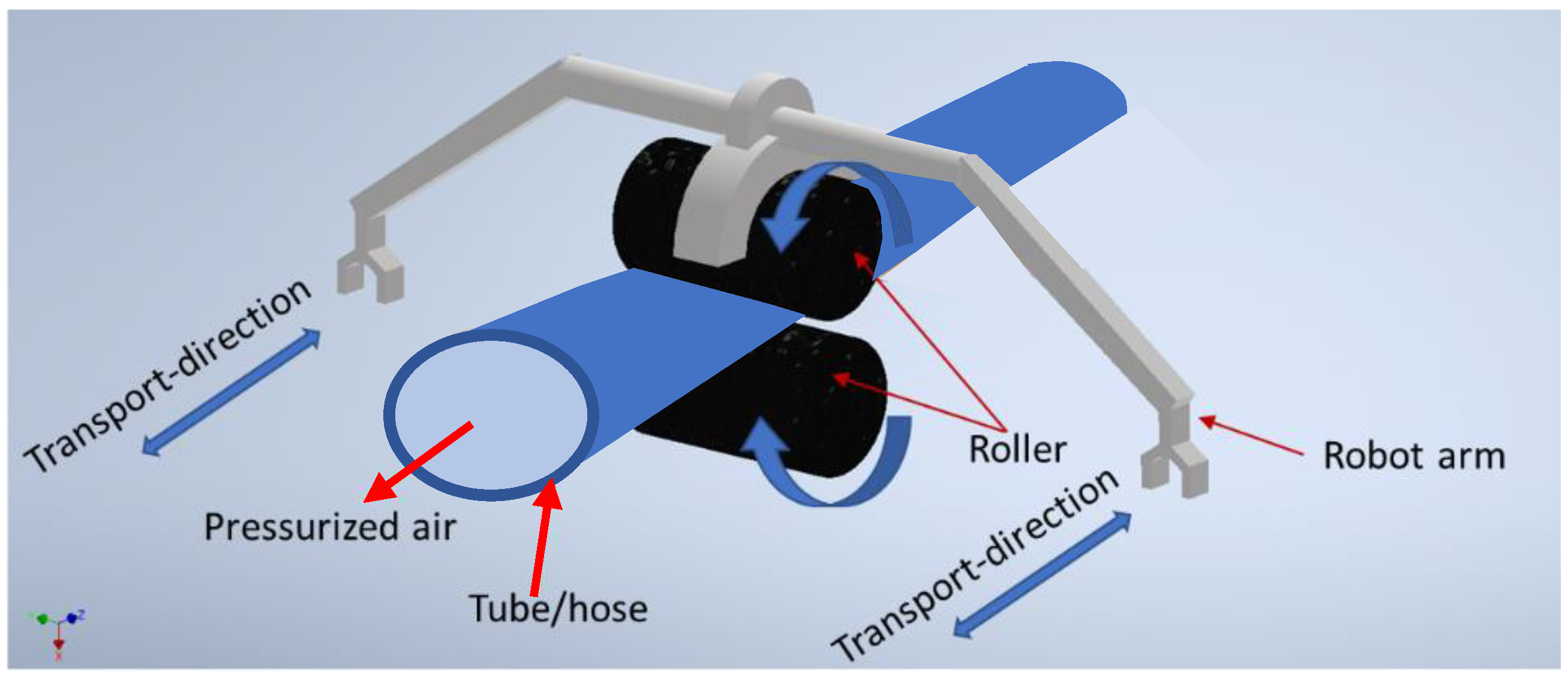
These actuators are driven by pneumatic energy. Their working principle is based on a moving piston composed by two rollers that press a hose to form two isolated chambers (see Figure 1). When air is pumped into one of the chambers, a force is developed that pushes the rollers in the direction of the opposite chamber.
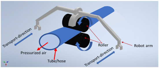
Figure 1.
Schematic view of the working principle of PLPA.
PLPA present several advantages over conventional ones as they have a virtually unlimited stroke, low cost, can perform curved profiles and exhibit beneficial friction properties for servocontrol purposes [11]. One drawback of this technique is the limited endurance of the pressurized and at the same time compressed hose, which compromises its industrial application.
In this context, preliminary investigations using conventional hoses have reported crack formation in the hose folded sides that were exposed to the roller forces [7,12]. Following these studies, this paper focuses on developing new geometries in order to investigate the endurance of the hose integrated in a PLPA actuator setup. To develop such new geometries, this study uses Additive Manufacturing (AM) namely called 3D printing for fabricating functional prototypes. It is expected that 3D printed PLPA are not directly appliable in industrial applications, as they lead to very small endurance values when compared, for instance, with conventional pneumatic cylinders. So, from an industrial perspective, other techniques such as injection molding or extrusion should be used. However, to make preliminary assessments on the potential benefits of using new PLPA designs, namely to compare new designs against the more conventional one (circular design), 3D printing offers a design flexibility which is harder to achieve by conventional techniques.
Towards this goal, initial experiments were done by the authors using the Stereolithography (SL) technique [7]. Hose prototypes were fabricated using Formlabs 2 Stereolithography 3D printer and Formlabs flexible resin (FLFLGR02) material. The printed samples however cracked almost immediately after the start of the experimental tests. It should be noted that the hoses must survive a considerable number of fatigue cycles to serve as functional prototypes. If this is not ensured, no clear conclusions can be drawn due to the high standard deviation found in the results of sample endurance tests. As such, in this study the Fused Layer Manufacturing (FLM) of Thermoplastic Polyurethane Elastomer (TPU) is investigated as an alternative AM technique to SL. TPUs are typically characterized by very low intermolecular forces and a low Young’s modulus supporting strains on the order of hundreds of percentages [13]. These characteristics make TPU attractive for 3D printing of soft, flexible components [14,15,16,17,18], specially in the fields of biotechnology [19] and robotics [1,2,3,20].
Given the scenario presented above, the first step towards a successful printed prototype would be finding the optimum FLM processing parameters such as the printing temperature and the build direction [15,17,21,22]. This study is therefore aimed at two goals. The first goal was the investigation of using TPU for PLPA application by analyzing the following points:
- experimentally determining the TPU material properties;
- finding the optimum print temperature, not only for manufacturing a robust product but also when considering the actuator endurance;
- finding an adequate printing angle.
The second goal was the assessment of the influence of the hose design on the hose endurance. As such, two designs were considered (please check Table 1):

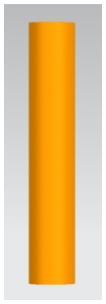
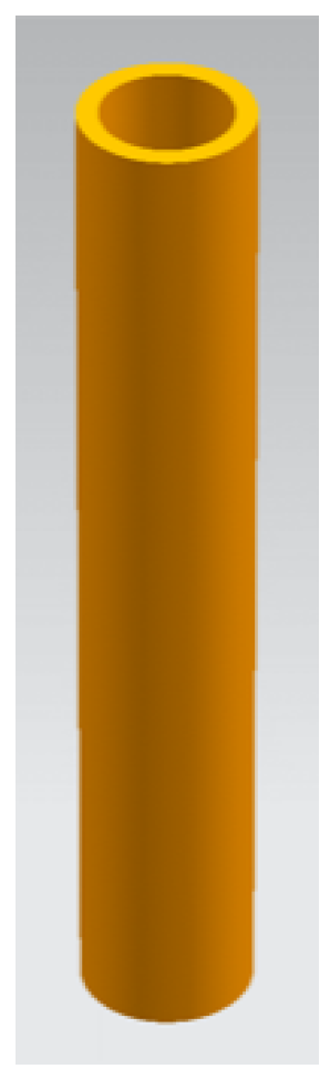
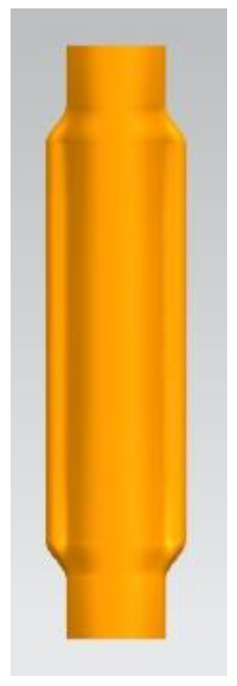
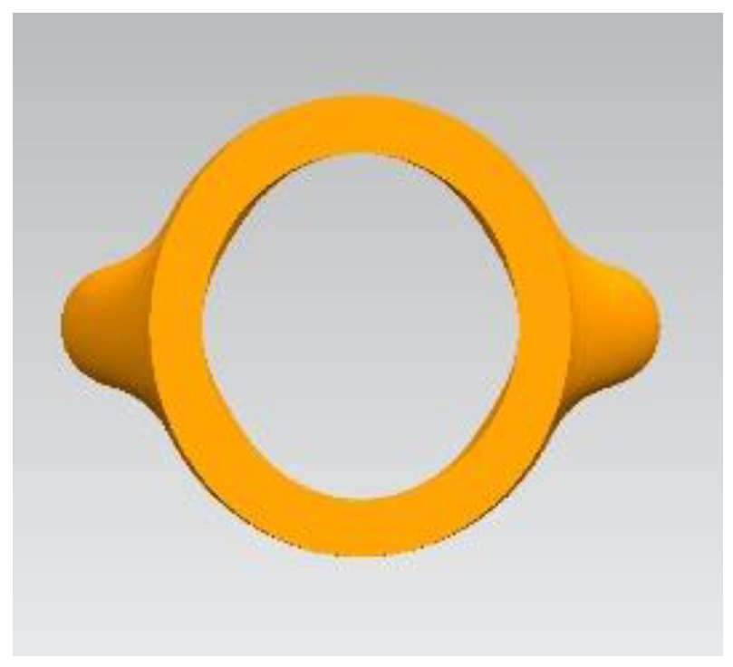
Table 1.
Different views of hose designs A and B.
- design A: conventional circular hose;
- design B: geometrically reinforced hose design at the folding region;
2. Experimental Setup
2.1. Material Characterization
The 3D printing experiments were done using FLM of TPU. TPU filament supplied by RECREUS, the 82A FILAFLEX, was used as the print material. In order to find the processing temperature range and the print temperature of the TPU material, the FILAFLEX was analysed using Scanning Calorimetry (DSC) Mettler-Toledo DSC Typ 3+. Measurements were conducted under nitrogen gas environment in the temperature range of −80 °C to +260 °C at a heating rate and cooling rate of 20 °C/min. The DSC sample mass was approximately 5 mg. Sealed aluminum crucibles with perforated lid were used for the thermal analysis investigation. First and second heating curves as well as the crystallization curve were measured, which represent the melting and crystallization behaviour of the investigated samples.
Once the printing temperature range was set, mechanical proprieties of different test geometries (tensile test samples) printed using different print temperatures were examined. This was done in order to identify any possible correlation between the endurance of the hoses (exposed to the internal pressure and the rollers forces in the PLPA setup) and the tensile strength of the printed samples, which could be useful for future hose design studies. In order to have a reference value for mechanical properties, initial tensile tests were done by stretching the TPU filament. Mechanical tests were performed on the TPU-filament as well as on printed dumbbell-specimens type 5A according to ISO 527 using a Zwick/Roell tensile tester type Z005 with a load measuring cell of 500 N at room temperature. The cross-head speed was set at 5 mm/min in case of the filament and 100 mm/min for testing the printed samples. Fixation of the samples were conducted using wedge-type clamping. Stress strain curves were recorded, and the nominal strain calculated, as to be the ratio between displacement with respect to free clamping distance. Tensile tests were conducted on the TPU-filament and printed tensile samples.
2.2. 3D Printer
For printing the hose samples, Anycubic i3 mega and Ultimaker S5 3D printers were used. The use of two available printers in parallel helped with shortening the sample printing time. Parts were printed using 100% infill with a layer thickness of 150 μm. All parts in this study were printed using the offset scan strategy, printing the outer layers with a spiral path towards the center of the part. Preheating of the print bed was disabled during the print process. Printing temperatures were set based on the DSC results, which will be introduced in Section 4.1.
2.3. Pneumatic Test Bed
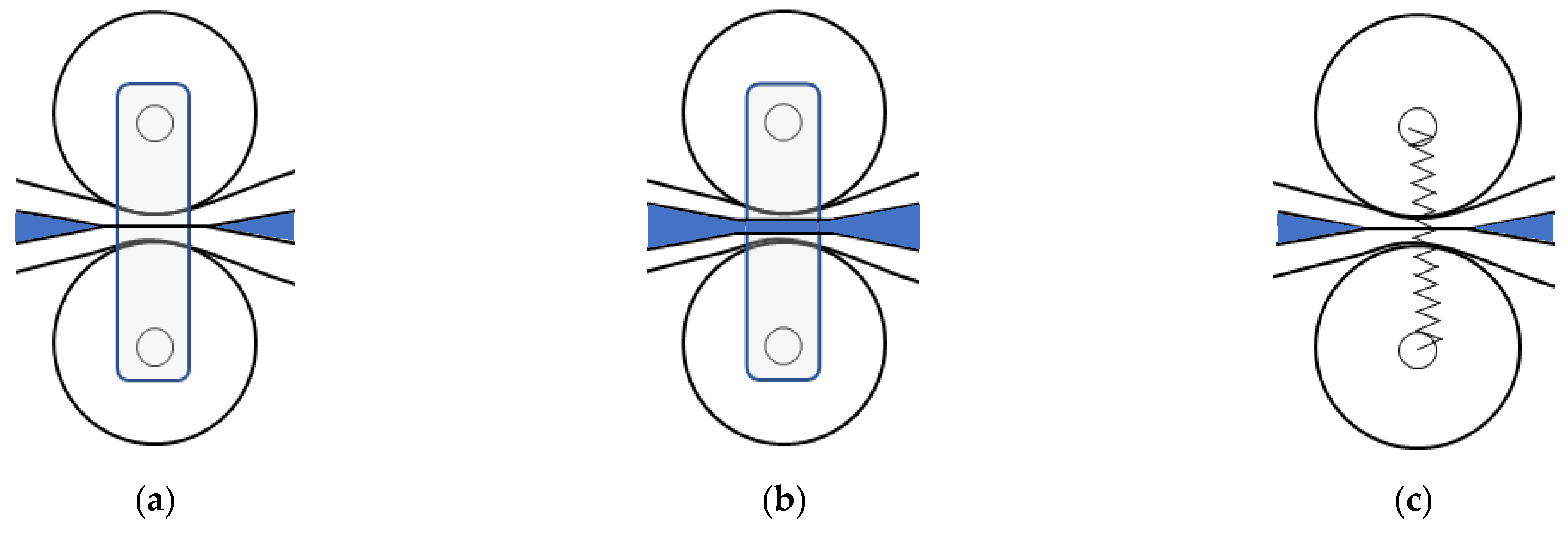
As described above, the working principle of a PLPA is based on a hose compressed by two rollers so that two independent chambers are formed. A good seal between chambers is crucial as leakages represent a waste of energy and reduce the amount of available force. In early prototypes of the PLPA developed by the authors, the distance between the rollers was imposed by mechanical construction, as depicted in Figure 2a. However, since the hose walls get thinner as the rollers compress it, the leakages tend to increase during the actuator lifetime, as shown in Figure 2b. To solve this problem, the authors have developed a prototype in [7,8] with springs to ensure that a nearly constant force between rollers is imposed, as depicted in Figure 2c. The force imposed by the springs, namely how it influences the leakage between chambers, is described in detail in reference [8], and the amplitude of the force that can be produced by the PLPA is described in detail in reference [9].
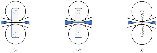
Figure 2.
Different configuration of the rollers: (a) Distance between rollers is imposed; (b) decreased thickness due to wear leads to leakage in configuration a); (c) force between rollers is imposed.
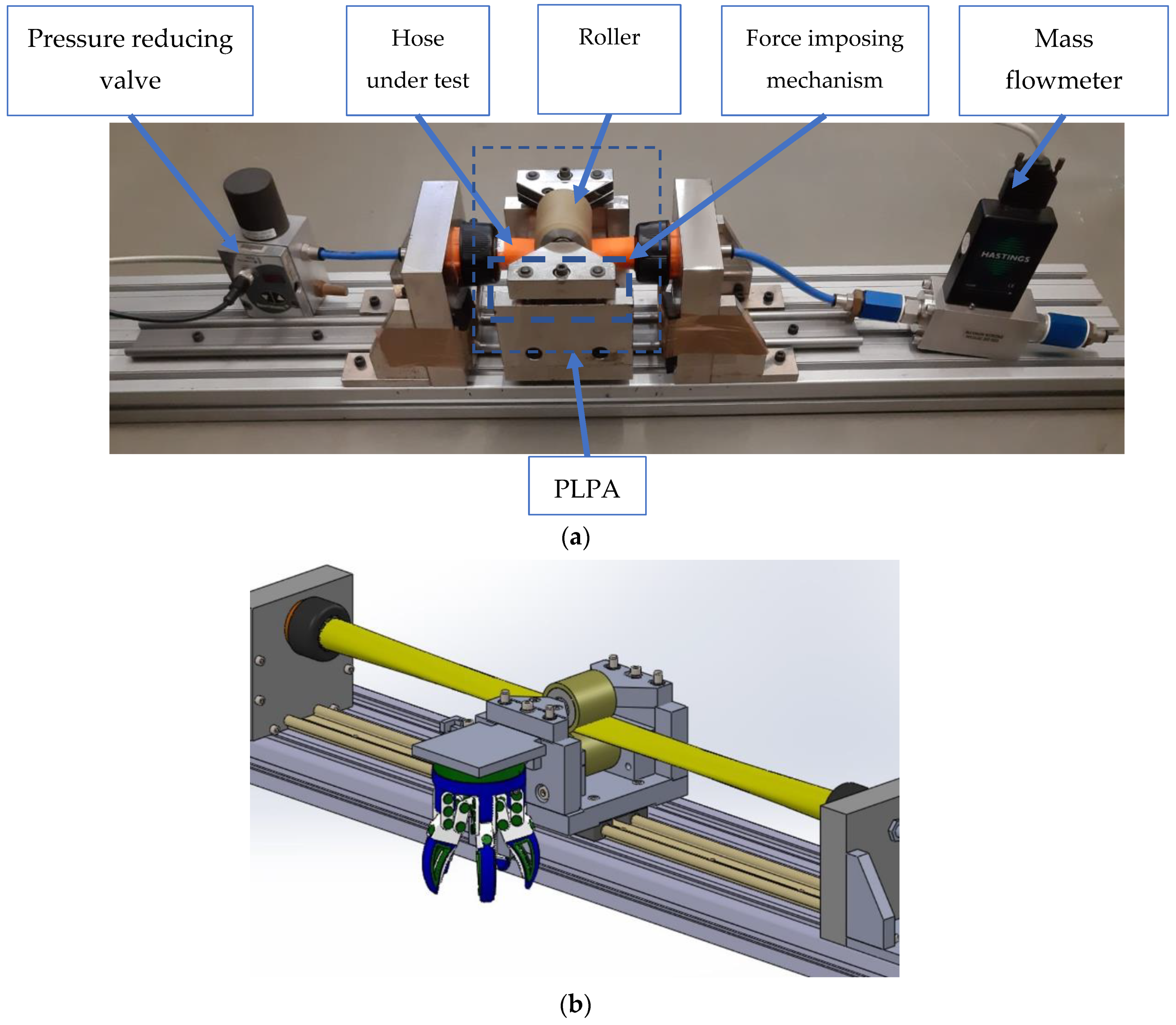
It has been shown that the configuration presented in Figure 2c leads to a considerable increase in the hose longevity [7] and therefore the PLPA used in this work also uses this approach. Figure 3a presents a picture of the experimental setup and Figure 3b presents a 3D render of the setup including a gripper to perform pick and place tasks.
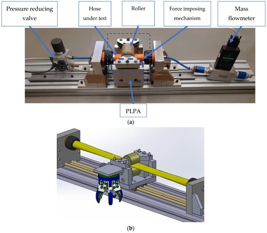
Figure 3.
(a) Picture of the experimental setup; (b) 3D render including a gripper for pick and place operations.
The force between rollers was adjusted using two spring washers in such a way that after assembly, the leakage between chambers was lower than 5 slpm. To determine these leakages, the experimental setup shown in Figure 3a was used. This setup includes a mass flowmeter Hastings HFM 301 and also a proportional pressure reducing valve (Numatics Sentronic D), set for 3 bar (relative) working pressure.
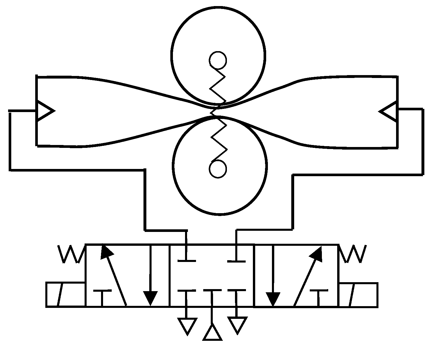
The back-and-forth motion of the carriage is obtained using the pneumatic circuit represented in Figure 4 where the solenoids of the valve are commanded to obtain an oscillating behaviour between the actuator stroke limits [12].
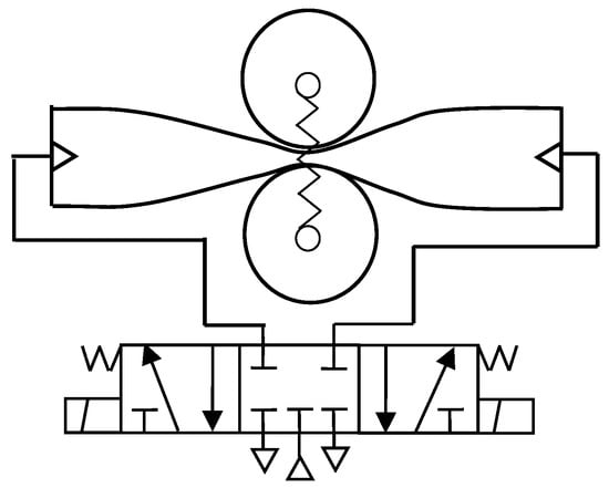
Figure 4.
Pneumatic circuit used to impose back and forth motion to the actuator.
3. Procedure
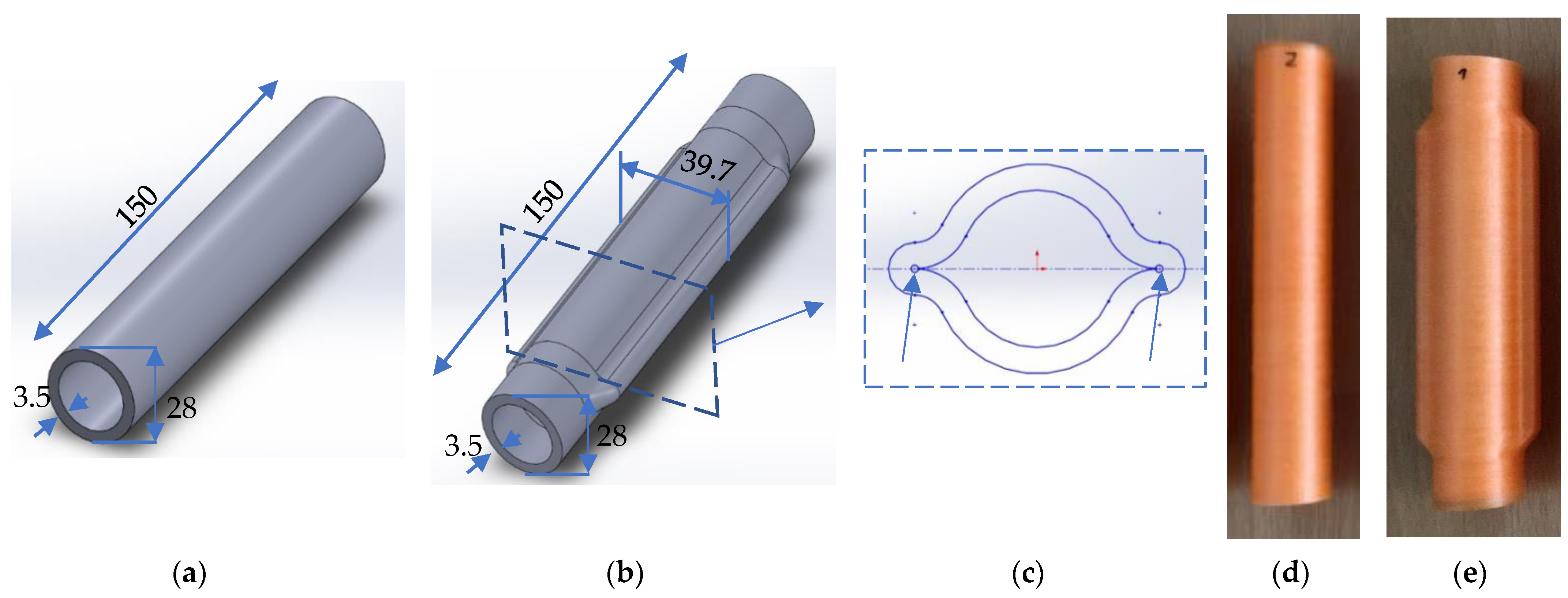
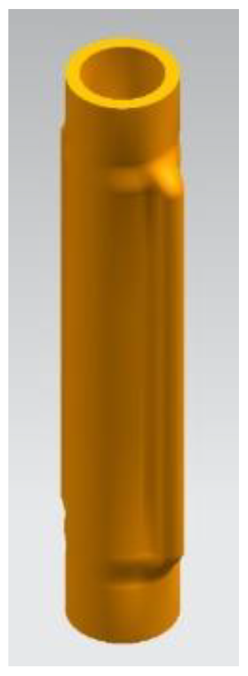
As mentioned in the introduction, two hose designs were considered in this work—designs A and B. Figure 5a,b present the detailed CAD models of these designs while Figure 5d,e present the corresponding printed hoses. Design A is a conventional circular one and design B is intended to improve the material strength at the folding region. More specifically, the goal of design B was to diminish the angle that the hose must undergo while being compressed. In the traditional design A, the hose edges are bent when compressed, while in design B the “lip-shape” prevents bending. This is expected to increase the endurance since it leads to less deformation in the hose edges. However, design B rises the stress concentration factor due to the inside pressure. As such, a circular cross section near the folding region was added, as indicated by the arrows in Figure 5c. The profile thickness of design B was selected to ensure that when fully pressed by the rollers, design B leads to a totally flat hose. The flatness of the hoses is important as it enables a uniform pressure distribution along the hose profile. This, in turn, contributes to the minimum possible leakage of the setup, increasing the efficiency of the PLPA actuator.

Figure 5.
Geometrical details of the different designs: (a) Design A; (b) Design B; (c) Detail of design B; (d) Design A: 3D printed part; (e) Design B: 3D printed part.
In order to assess the influence of the printing parameters on the hose prototype performance, the more adequate printing temperature was firstly determined. To this end, the results obtained from the DSC measurements (see Section 4.1) were used to determine the temperature range for printing the hoses. A set (set 1) of different hoses printed at the same printing angle and design (design A), but at different temperatures, was considered for the initial trials (see Table 2). Three samples of each hose configuration presented in Table 2 were tested.
Table 2.
Sample set 1—different hose configurations for design A.
To access the influence of the printing angle on the hose endurance behavior, the initial goal was to print several hoses at 0°, 45°, and 90° degrees, as illustrated in Figure 6, and test their endurance in the PLPA actuator setup. Initial experiments showed that:
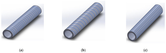
Figure 6.
Illustration of layer orientation within the samples which were printed using different printing angles: (a) 0°; (b) 45°; (c) 90°.
- The 90° printing angle led to considerably less endurance than the other two (an average of 2459 cycles with 90° versus 13,058 cycles with 0° for design A), so the 90° printing angle was not further considered;
- The 45° angle hoses required support structures that could not be implemented in the available printer (Anycubic i3 mega). In order to overcome this difficulty, the printing angle was slightly reduced to 35°, which did not require support structures.
Given the above restrictions, two different printing angles were selected for the endurance tests performed in the next section: 0° and 35°.
Using the experimental setup presented in Section 2.3, a continuous back and forth motion of the actuator was imposed until failure. Given the dimensions presented in the previous section, the useful actuator stroke was of 60 mm. A source pressure of Ps = 3 bar was used. Three samples of each hose configuration with the force adjustment setup presented in Section 2.3 were tested. The leakages between chambers were measured at the beginning of the trials and at approximately half of the life span. Since the life span of each hose was not known a priori, the life span was estimated by running continuous back and forth cycles in an initial trial hose, to investigate the number of cycles until failure of that particular hose. Subsequent hoses were then tested at half of that number of cycles. The procedure was the same for all tested samples.
4. Results and Discussion
4.1. Material
Figure 7 shows the DSC-curves of the filament and a representative 3D printed sample processed at 260 °C throughput of the printing device. It is found the TPU filament shows a glass transition temperature of about −30 °C and a wide endothermal melting range starting at about 60 °C and ending up at 185 °C. There are two distinct melting ranges found: the peak temperature of the first is about 70 °C and second peak locates at about 160 °C. After melting the TPU up to 260 °C it crystallizes within a single exotherm at about 75 °C. During re-melting the first melting peak does not recover and the melting peak appears at 164 °C. In the molten state above 185 °C the DSC curve bends progressively towards endothermal direction, which indicates an ongoing thermal stimulated degradation of the polymer.
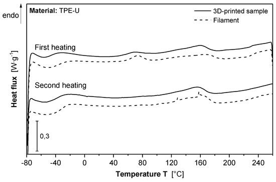
Figure 7.
DSC-curves of filament and 3D printed specimen type 5 A according to ISO 527.
The investigated melt crystallization peak temperature of the TPU material is about 76 °C and relatively deep, which favors a slow solidification process and may provide enhancing the strength of 3D printed parts out of that material.
As the DSC results showed, no clear melting point can be set for selected TPU. As such, the initial print trials were done using the temperature of 160 °C (second peak mentioned in DSC curve) to 260 °C with a 10 °C interval. The print results have shown that the first visually stable part can be printed only after applying a print temperature of 210 °C. In addition, no visually stable parts could be printed using temperatures higher than 260 °C. The printed part using 210 °C and 260 °C underwent defects which later caused leakage when tested in the actuator setup.
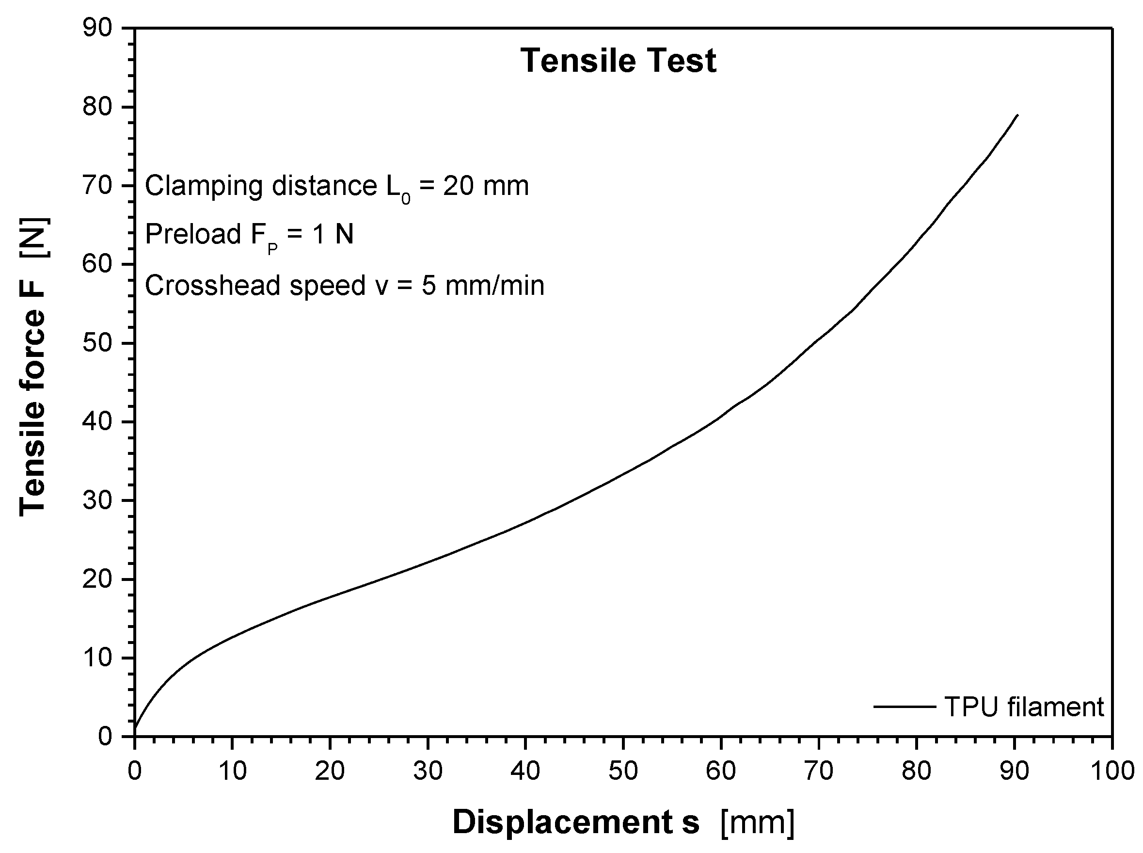
Figure 8 represents the force displacement curve of the TPU filament under tensile loading. The strength of the filament is about 30 MPa at a filament diameter of 1.8 mm, which was tested, and the strain at break is about 450%.

Figure 8.
Force vs. displacement curve measured on the filament.
Table 3 shows the average strength values measured on differently processed 3D printed tensile specimens from the TPU elastomer.
Table 3.
Strength data of differently processed 3D printed tensile specimens of type 5A according to ISO 527, average values obtained with three samples.
As the results in Table 3 show, tensile samples that were printed using different print temperatures (220 °C to 260 °C) show a minimum and maximal strength of approximately 12 MPa to 22 MPa. The samples printed using a temperature of 240 °C led to the maximum tensile strength with a slight difference compared to the tensile strength of samples printed using other temperatures. These results will be further compared with the endurance test results of samples printed at different temperatures and their possible correlation will be discussed.
4.2. Actuator Endurance
Hoses A-0-220 were not subject to any endurance test because although none of the samples presented any observable flaw, they all burst before reaching the pressure used in the tests (3 bar). The average of the number of cycles each hose performed is presented in Table 4.
Table 4.
Average of the number of cycles of each hose in sample set 1 performed until failure.
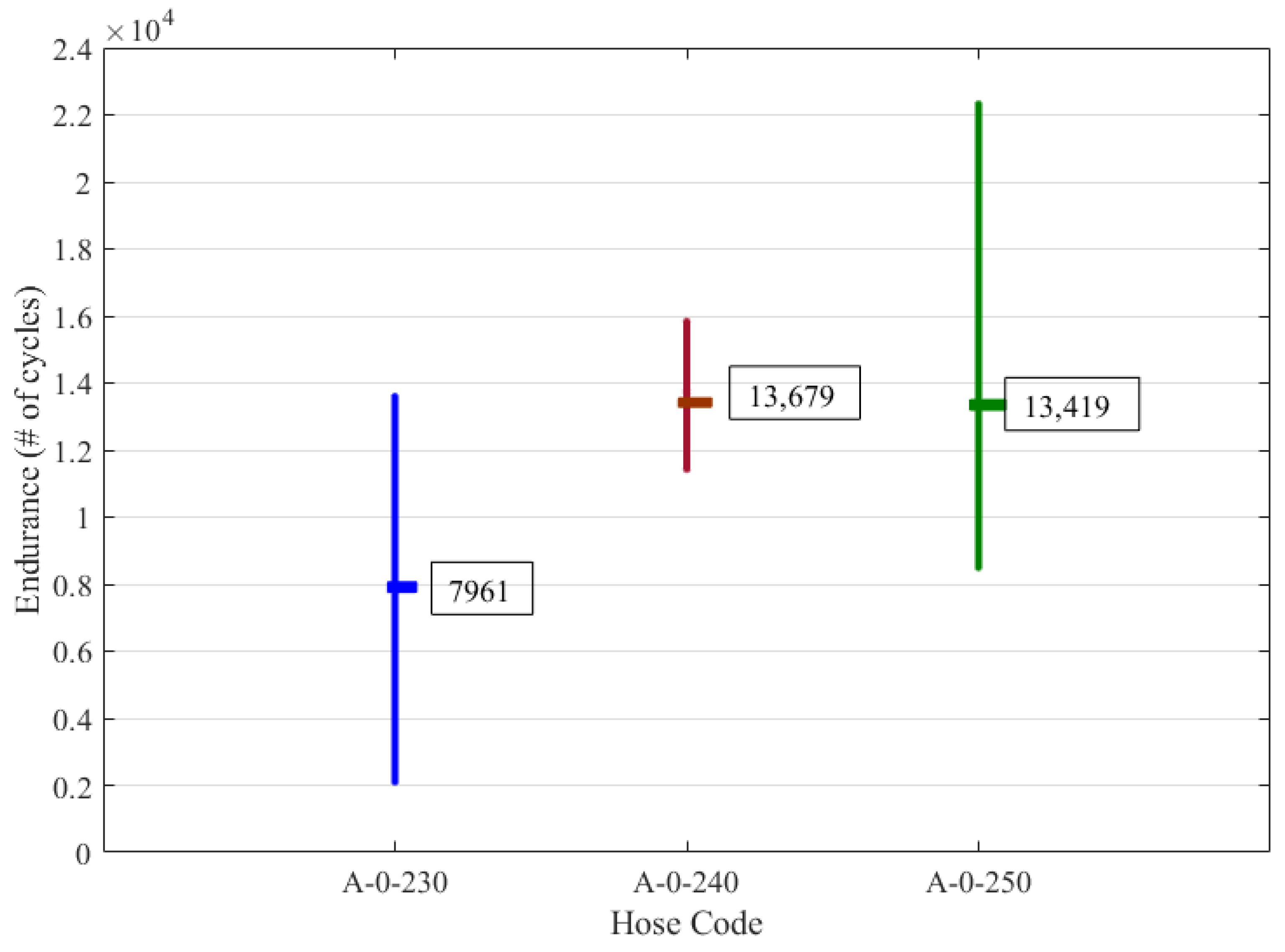
A comparison between A-0-230, A-0-240, and A-0-250 allows the assessment of the printing temperature influence. Results indicate that the optimum temperature range is between 240°C and 250°C, as can be seen in the graph presented in Figure 9. In fact, and as mentioned before, samples printed with temperature equal to 220 °C or below led to either big printing flaws (T < 220 °C) or to a burst of the hose before reaching the test pressure (T = 220 °C). Temperatures above 250 °C led to visible printing flaws that compromised a proper behaviour.

Figure 9.
Influence of printing temperature: average, minimum, and maximum number of cycles.
Based on the results previously obtained, a printing temperature of 240 °C was set as the one to use in the assessment of different designs and printing angles. This choice is justified by the fact that this printing temperature led to lower dispersion of the results when compared to 250 °C. Three samples of each hose configuration presented in Table 5 were tested for design and printing angle comparison (set 2). The results are presented in Table 6 and in Figure 10.
Table 5.
Sample set 2: different hose configurations for printing angle and design assessment.
Table 6.
Average of the number of cycles each hose in sample set 2 performed until failure.

Figure 10.
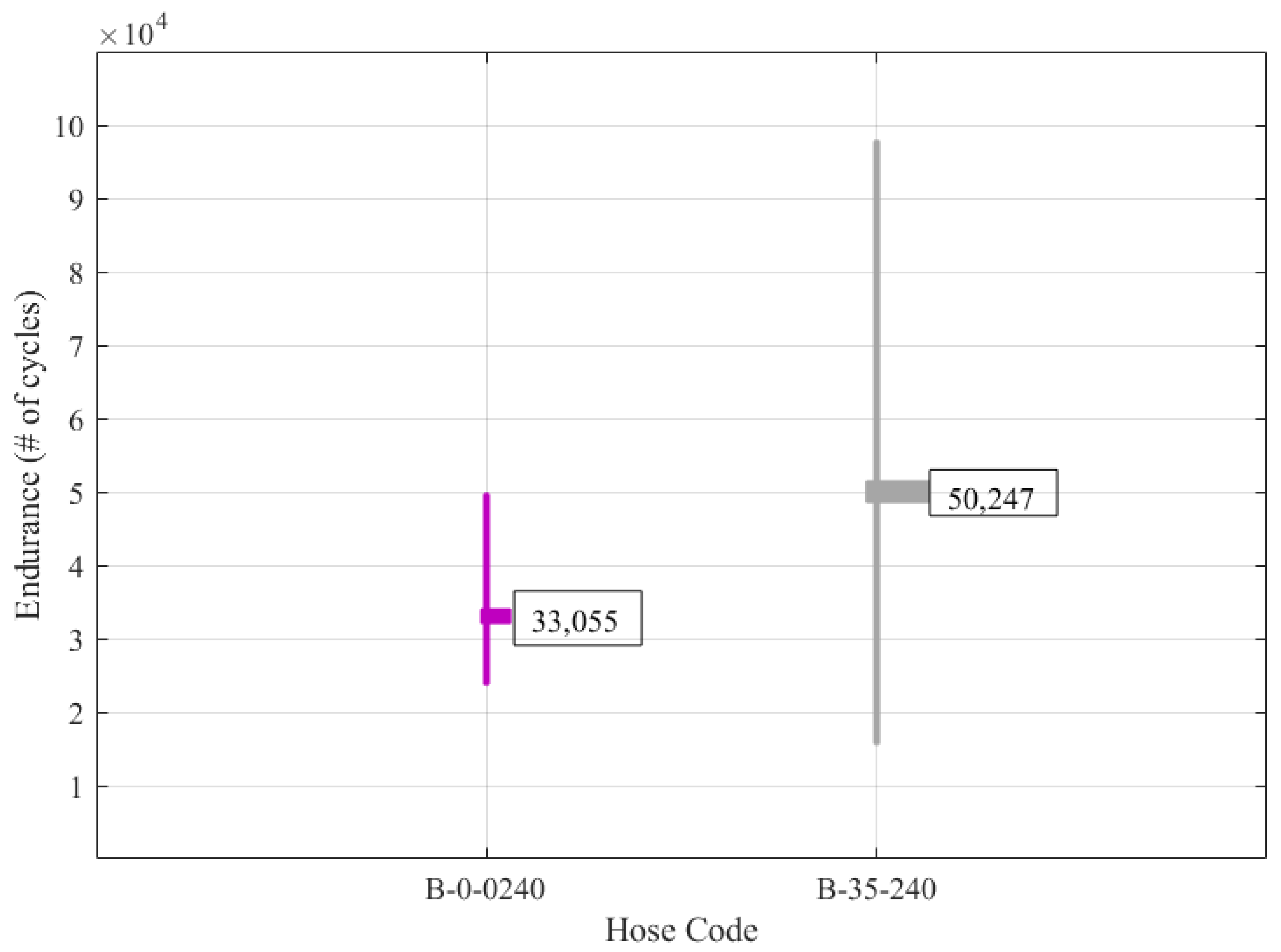
Influence of the printing angle in the hose endurance: average, minimum, and maximum number of cycles.
Regarding the influence of the printing angle, a comparison between set 2 samples reveals that the 35° printing angle leads to a higher average endurance. This result should nevertheless be interpreted with caution as there is a big standard deviation of the B-35-240 results.
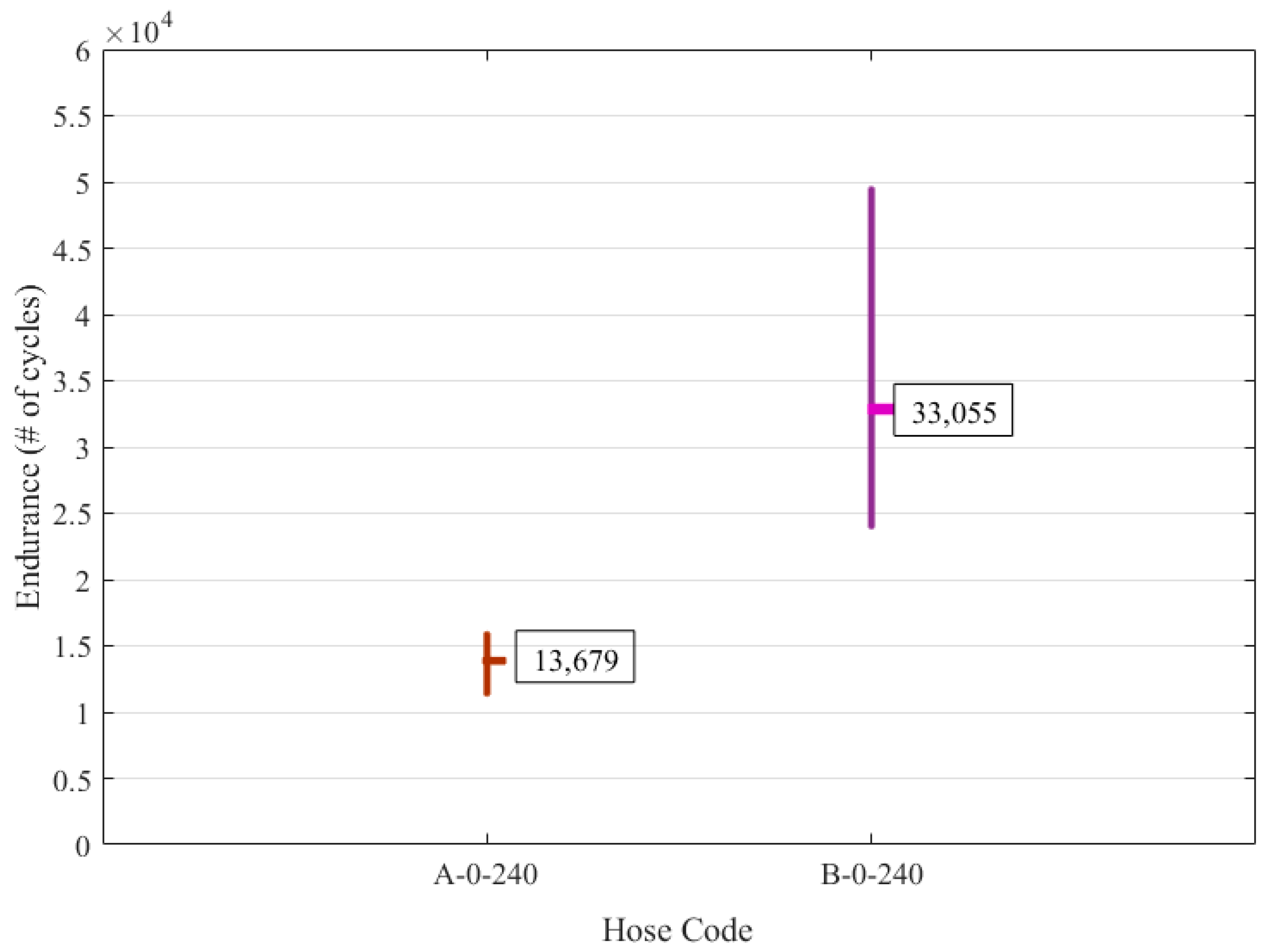
Finally, the analysis of A-0-240 and B-0-240 results allows a direct comparison between designs A and B, as shown in Figure 11. These results indicate that design B clearly leads to a longer endurance than design A, as the average endurance of design B is more than twice the one of design A. This is a very interesting result as it indicates that hose design shaping might play a crucial role in the endurance of the actuator. To further validate this conclusion, three extra samples for configurations A-0-240 and B-0-240 were tested. The average number of cycles for each 6 samples set was 14,244 and 34,197, respectively, thus confirming that design B is in fact promising when compared to design A.
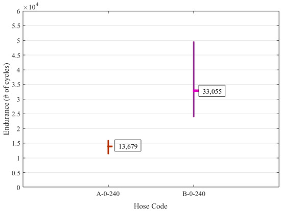
Figure 11.
Influence of design in the hose endurance: average, minimum, and maximum number of cycles.
It should be highlighted that previous literature results [7] have already tried to prove if different hose designs lead to better endurance. However, in that study, the material used to build the prototypes led to very short life cycles, thus compromising any valid conclusions. Given the above discussion, the use of design B, printed at 240 °C and with a print angle of 35° leads to the best results obtained in this comparison. These results should nevertheless be considered as preliminary, since the big dispersion found in the longevity results prevents more robust conclusions.
5. Conclusions
In this study, different hoses for PLPA were printed using TPU and the FLM method, while applying different designs, processing temperatures, and build angles. The main novelty of this work is concluded hereafter:
- a processing temperature of 240° C and a build angle of 35° yields the highest life cycle among the tested parameters.
- It has been confirmed that the 3D printed PLPA are not directly appliable in industrial applications as their endurance values are very small. However, the preliminary tests presented in this study show that hose designs that are different from the typical circular one might play a crucial role in the hose endurance of the actuator. In fact, it was shown that the hose design including geometrical reinforcements at the sides underwent more than twice the life cycle of a conventional hose design.
- Tensile test of samples processed at different print temperatures showed that samples printed using a temperature of 240 °C led to the maximum tensile strength. Similar results were observed when exposing different hoses to the endurance test. As such, it can be concluded that, the tensile strength of printed samples could have a direct relation with the endurance of the hoses being exposed to the internal pressure and external forces of such PLPA actuators.
It should be mentioned that the conclusions obtained from this work are also potentially applicable to a wider range of peristaltic based devices, namely to the more common peristaltic pumps. Future work will focus on:
- investigation of more tailored designs to assess the possibility of further increasing the hose longevity. To this end, FEM simulations of the PLPA at work will be run in order to pinpoint the main critical regions. This will allow the optimization of the hose shape.
- the use of a PLPA for water hydraulics. In fact, water hydraulics (as opposed to oil hydraulics) have a lower ecological footprint. The use of PLPAs might be advantageous in this field since the PLPA actuator is rubber based and therefore one of the main difficulties in water hydraulics (corrosion) is naturally surpassed.
- Exploring the inclusion of 3D printed metal alloys [23,24] in the hose manufacturing process, to produce prototypes with possibly improved mechanical proprieties.
Author Contributions
Conceptualization, M.F. and J.F.C.; methodology, M.F., J.F.C., F.G.d.A. and A.F.; software, J.B.P. and M.F.; investigation, M.F., J.F.C., F.G.d.A. and A.F.; resources, M.F., J.F.C., F.G.d.A. and A.F.; data curation, J.B.P. and M.F.; writing—original draft preparation, J.F.C., A.F. and M.F.; writing—review and editing, M.F., J.F.C., J.B.P., F.G.d.A. and A.F. All authors have read and agreed to the published version of the manuscript.
Funding
This work was financially supported through contract LAETA—UIDB/50022/2020 by “Fundação para a Ciência e Tecnologia”, and also funded by the Stiftung Kessler + Co. für Bildung und KulturStifftung, which the authors gratefully acknowledge.
Institutional Review Board Statement
Not applicable.
Informed Consent Statement
Not applicable.
Acknowledgments
Many thanks to Ralf Schreck from Hochschule Aalen for his great support during the project submission. Additionally, the authors wish to thank to Wolfgang Rimkus, Michael Hafner, Constantin Schule, Maximilian Pause, Philip Tremmel, Nico Butsch, and Jochen Hoffmann for their support in Additive Manufacturing Lab in HS Aalen. The authors would also like to thank Dennis Jahn and Markus Rettenberger from iPSP for carrying out material measurements.
Conflicts of Interest
The authors declare no conflict of interest.
References
- Zhalmuratova, D.; Chung, H. Reinforced Gels and Elastomers for Biomedical and Soft Robotics Applications. ACS Appl. Polym. Mater. 2020, 2, 1073–1091. [Google Scholar] [CrossRef]
- MacCurdy, R.; Katzschmann, R.; Youbin, K.; Rus, D. Printable hydraulics: A method for fabricating robots by 3D co-printing solids and liquids. In Proceedings of the IEEE International Conference on Robotics and Automation (ICRA), Stockholm, Sweden, 16–21 May 2016; pp. 3878–3885. [Google Scholar]
- Byrne, O.; Coulter, F.; Glynn, M.; Jones, J.; Annaidh, A.; O’Cearbhaill, E.; Holland, D. Additive Manufacture of Composite Soft Pneumatic Actuators. Soft Robot. 2018, 5, 726–736. [Google Scholar] [CrossRef] [PubMed]
- Mori, S.; Tanaka, K.; Nishikawa, S.; Niiyama, R.; Kuniyoshi, Y. High-Speed Humanoid Robot Arm for Badminton Using Pneumatic-Electric Hybrid Actuators. IEEE Robot. Autom. Lett. 2019, 4, 3601–3608. [Google Scholar] [CrossRef]
- Rouzbeh, B.; Bone, G.; Graham, A.; Li, E. Design, Implementation and Control of an Improved Hybrid Pneumatic-Electric Actuator for Robot Arms. IEEE Access 2018, 7, 14699–14713. [Google Scholar] [CrossRef]
- Li, S.; Vogt, D.; Bartlett, N.; Rus, D.; Wood, R. Tension Pistons: Amplifying Piston Force Using Fluid-Induced Tension in Flexible Materials. Adv. Funct. Mater. 2019, 29, 1901419. [Google Scholar] [CrossRef]
- Carneiro, J.F.; Pinto, J.B.; de Almeida, F.G.; Fateri, M. Improving Endurance of Pneumatic Linear Peristaltic Actuators. Actuators 2020, 9, 76. [Google Scholar] [CrossRef]
- Carneiro, J.F.; Pinto, J.B.; de Almeida, F.G.; Fateri, M. Model and Experimental Characteristics of a Pneumatic Linear Peristaltic Actuator. Information 2020, 11, 76. [Google Scholar] [CrossRef] [Green Version]
- Carneiro, J.F.; de Almeida, F.G. Experimental characteristics of a linear peristaltic actuator. In Proceedings of the 11th International Fluid Power Conference, Aachen, Germany, 19–21 March 2018. [Google Scholar]
- Baydere, B.; Talas, S.; Samur, F.E. A novel highly-extensible 2-DOF pneumatic actuator for soft robotic applications. Sens. Actuators A 2018, 281, 84–94. [Google Scholar] [CrossRef]
- Carneiro, J.F.; de Almeida, F.G. Friction characteristics and servo control of a linear peristaltic actuator. Int. J. Adv. Manuf. Technol. 2018, 96, 2117–2126. [Google Scholar] [CrossRef]
- Carneiro, J.F.; Pinto, J.B.; de Almeida, F.G. Endurance tests of a linear peristaltic actuator. Int. J. Adv. Manuf. Technol. 2019, 100, 2103–2114. [Google Scholar] [CrossRef]
- Holden, G.; Kricheldorf, H.; Quirk, R. Thermoplastic Elastomers, 3rd ed.; Hanser Publications: Cincinnati, OH, USA, 2004. [Google Scholar]
- Valino, A.; Dizon, J.; Espera, A.; Chen, Q.; Messman, J.; Advincula, R. Advances in 3D printing of thermoplastic polymer composites and nanocomposites. Prog. Polym. Sci. 2019, 98, 101162. [Google Scholar] [CrossRef]
- Gama, N.; Ferreira, A.; Barros-Timmons, A. 3D Printed Thermoplastic Polyurethane Filled with Polyurethane Foams Residues. J. Polym. Environ. 2020, 28, 1560–1570. [Google Scholar] [CrossRef]
- Stan, F.; Stanciu, N.; Constantinescu, A.; Fetecau, C. 3D Printing of Flexible and Stretchable Parts Using Multiwall Carbon Nanotube/Polyester-Based Thermoplastic Polyurethane. J. Manuf. Sci. Eng. 2020, 143, 051002. [Google Scholar] [CrossRef]
- Hohimer, C.; Christ, J.; Aliheidari, N.; Mo, C.; Ameli, A. 3D printed thermoplastic polyurethane with isotropic material properties. SPIE Smart Struct. Mater. Nondestruct. Eval. Health Monit. 2017, 10165, 1016511. [Google Scholar]
- Blok, L.G.; Longana, M.L.; Yu, H.; Woods, B.K.S. An investigation into 3D printing of fibre reinforced thermoplastic composites. Addit. Manuf. 2018, 22, 176–186. [Google Scholar] [CrossRef]
- Haryńska, A.; Gubanska, I.; Kucinska-Lipka, J.; Janik, H. Fabrication and Characterization of Flexible Medical-Grade TPU Filament for Fused Deposition Modeling 3DP Technology. Polymers 2018, 10, 1304. [Google Scholar] [CrossRef] [Green Version]
- Wohlers Report 2021: 3D Printing and Additive Manufacturing, Global State of the Industry; Wohlers Associates: Fort Collins, CO, USA, 2021; ISBN 9780991333271.
- Płatek, P.; Rajkowski, K.; Cieplak, K.; Sarzyński, M.; Małachowski, J.; Woźniak, R.; Janiszewski, J. Deformation Process of 3D Printed Structures Made from Flexible Material with Different Values of Relative Density. Polymers 2020, 12, 2120. [Google Scholar] [CrossRef]
- Herzberger, J.; Sirrine, J.M.; Williams, C.B.; Long, T.E. Polymer Design for 3D Printing Elastomers: Recent Advances in Structure, Properties, and Printing. Prog. Polym. Sci. 2019, 97, 101144. [Google Scholar] [CrossRef]
- Martínez, S.; Ortega, N.; Celentano, D.; Sánchez, A.; Ukar, E.; Lamikiz, A. Analysis of the Part Distortions for Inconel 718 SLM: A Case Study on the NIST Test Artifact. Materials 2020, 13, 5087. [Google Scholar] [CrossRef] [PubMed]
- Calleja-Ochoa, A.; Gonzalez-Barrio, H.; López de Lacalle, N.; Martínez, S.; Albizuri, J.; Lamikiz, A. A New Approach in the Design of Microstructured Ultralight Components to Achieve Maximum Functional Performance. Materials 2021, 14, 1588. [Google Scholar] [CrossRef] [PubMed]


Publisher’s Note: MDPI stays neutral with regard to jurisdictional claims in published maps and institutional affiliations. |
© 2021 by the authors. Licensee MDPI, Basel, Switzerland. This article is an open access article distributed under the terms and conditions of the Creative Commons Attribution (CC BY) license (https://creativecommons.org/licenses/by/4.0/).