Abstract
The objective of this study is to investigate the accuracy of Computational Fluid Dynamics (CFD) for simultaneously predicting the outdoor and indoor airflows of single-cell and multi-storey buildings. Empirical models and two existing wind tunnel experimental data are used for validation. This study found that coupled CFD simulations provide sufficiently accurate airflow predictions and, in cases of buildings with complex façade treatments, accurately accounts for changes in ventilation performance, which may be impossible using empirical models. This study concludes that coupled CFD simulations can generally be used to predict ventilation performance in small and large buildings.
Nomenclature

 | Inlet opening area | (m2) |
 | Outlet opening area | (m2) |
 | Opening area | (m2) |
 | Opening area, refer to Equation (5) | (m2) |
 | Opening discharge coefficient | (-) |
 | Constant (windward/ parallel wind: 0.0012 and, leeward wind: 0.0026) | (-) |
 | Pressure coefficient | (-) |
 | Opening effectiveness | (-) |
 | Wind speed | (ms−1) |
 | Reference wind speed | (ms−1) |
 | Pressure | (Nm−2) |
 | Ventilation rate | (m3s−1) |
| Greek Letters or other Symbols | ||
 | Air density | (kgs−3) |
1. Introduction
Building design has become more complex, therefore, to optimise the natural ventilation performance of a passive design strategy in a complex building design, a simple, flexible and accurate ventilation prediction model is required. There are various airflow prediction models available that predict the ventilation performance of buildings: full-scale, small-scale, Computational Fluid Dynamics (CFD) and empirical models. Each of these models has their own advantages and disadvantages that make them unique [1,2].
In the case of a simple flat facade single-cell room, empirical models alone are generally adequate for predicting the indoor ventilation performance for both single-sided and cross ventilation strategies. However, in complicated scenarios, such as a room with a balcony and multiple openings, the use of empirical models, such as the pressure difference method, may not be appropriate. This is because the use of wind pressure data to calculate ventilation performance does not include factors, such as changes in the external wind characteristics (e.g., turbulence and direction), that result from the balcony. Thus, the three other models would be more appropriate in these complicated cases.
In the case of multi-storey buildings, a single prediction model is generally insufficient. In this case, it is common to use a combination of two airflow prediction models to predict ventilation performance. Two common approaches for predicting the ventilation performance of multi-storey buildings are a combination of small-scale and empirical models or combination of CFD (external airflow only) and empirical models. The second approach is common because CFD models are only used to predict airflow around a building, and wind pressure data on building facades are used to predict airflow rates using empirical models. However, this approach is not suitable for complex facade buildings with protrusions or protruding and sunken floor layouts. In these buildings, complex airflow characteristics exist close to the building surface and data obtained from wind pressure measurements on the facade are unable to accurately predict the influence of these characteristics on indoor airflow.
Recently, the use of CFD models alone to predict outdoor and indoor airflow has become an increasing important approach for ventilation prediction. Here, simulations can be divided into two categories: coupled and de-coupled CFD simulations. Coupled CFD simulations simultaneously simulate outdoor and indoor domains, while decoupled simulations simulate these domains separately. Coupled CFD simulations are preferred over de-coupled simulations due to its accuracy despite being more computationally intensive [3]. Most of the research that use coupled CFD simulations is limited to a few storey high buildings, such as in the work by Prianto and Depecker [4], Chow [5], Wang et al. [6], Wang and Chen [7] and, Allocca et al. [8]. Recent researches by Ai et al. [9] and van Hooff and Blocken [10], have shown that the approach is becoming more widely used for large buildings and multi-storey buildings of five stories and greater.
Among all of the aforementioned airflow prediction models, CFD is the most popular method for predicting ventilation performance in buildings [1] and its application will continue to expand in the future [3]. The popularity of the CFD method is a result of its cost efficiency, flexibility, prediction accuracy and comprehensive information. However, CFD has two major limitations: it requires a huge computational effort and its results are difficult to assess. While the computational requirements of CFD can be addressed with more powerful computers and parallel processing, the second limitation requires a validation process to assess the results.
The difficulty in assessing CFD predictions is a result of the sensitivity of CFD setups, which could lead to a wide range of inaccuracies and misleading predictions. Thus, it is important to comprehend the limitations of CFD predictions in the context of its accuracy to effectively and appropriately apply its predictions in a real environment. The prediction of the outdoor and indoor airflows in buildings is also subject to the limitations of CFD models. Therefore, the objective of this study is to investigate the accuracy of CFD for simultaneous prediction of the outdoor and indoor airflows of single-cell and multi-storey buildings.
2. Methodology
Before proceeding to the discussion on research methodology, it is important to note that this study only focused on wind-driven ventilation, and therefore, the effects of thermal-driven ventilation are excluded.
As mentioned in the introduction, the authors categorised the prediction methods into the following five approaches:
- Approach A: Fully empirical models;
- Approach B: Physical models (small or full scale) models;
- Approach C: Combination of physical and empirical models;
- Approach D: Combination of CFD and empirical models;
- Approach E: Fully CFD models (coupled or de-coupled).
The appropriate application of the aforementioned approaches is dependent on various factors, such as the size and complexity of a building as well as prediction information required. For Approach E, this study was only concerned with coupled CFD simulations because of its improved accuracy, and de-coupled simulations were excluded.
This study employs two stages of investigation based on two existing wind tunnel experiments. In the first stage, Approach E with a coupled CFD simulation is used to predict the ventilation performance of single-cell rooms with single-sided and cross ventilation. The predicted results are compared with the predictions by one of the other approaches as a validation study. In this first stage, the building models are variations based on the work of Givoni [11].
In the second stage, the work of Ismail [12] is used as a reference. The validation study is completed in two parts; wind pressure distribution followed by ventilation rate. To validate the wind pressure distribution, data from Ismail is used. To validate the ventilation rate obtained using Approach E (coupled CFD simulation only), Approaches C and D are used. Finally, the findings in both stages are analysed and the accuracy and reliability of Approach E are identified.
3. Empirical Models
There are various empirical models available for predicting single-sided and cross ventilation. Equation (1) to Equation (4) are common empirical models that can be used to predict the ventilation performance of a room.

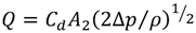
Equation (1) is the simplest and most common equation that can be applied to a simple single cell room or low-rise buildings. It can be applied to both single-sided and cross-ventilated rooms. The value for is taken as total opening area for a single opening room or area of inlet opening for a room with two similar sized openings. According to ASHRAE [13], in a cross-ventilated room, the values of are between 0.5 and 0.7 for perpendicular wind and 0.25 to 0.35 for diagonal wind. However, a study by Larsen [14] suggests that the value for diagonal wind is 0.48, but the opening area used in this study is only equal to 1% of the total area of the facade. In the case of a single-sided ventilation, the value is either 0.025 [15,16] or 0.02 [17].
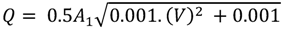
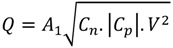
is taken as total opening area for a single opening room or area of inlet opening for a room with two similar sized openings. According to ASHRAE [13], in a cross-ventilated room, the values of are between 0.5 and 0.7 for perpendicular wind and 0.25 to 0.35 for diagonal wind. However, a study by Larsen [14] suggests that the value for diagonal wind is 0.48, but the opening area used in this study is only equal to 1% of the total area of the facade. In the case of a single-sided ventilation, the value is either 0.025 [15,16] or 0.02 [17].Equation (2) is an empirical model that applies a pressure difference method. It can be applied to both single-sided and cross-ventilated rooms. The accuracy of the prediction using these equations partially relies on the value for , which is dependent on various factors, such as wind direction and opening configuration. For a single-cell room, the values for range between 0.5 and 0.9 depending on the opening configuration [18]. For an opening area less than 10% of the facade, the values are between 0.5 and 0.65. While the first two equations can be applied to both single-sided and cross-ventilated rooms, Equation (3) [19] and Equation (4) [14] are limited to single-sided ventilation. In Equation (4), the values used are taken from Liddament [20].
, which is dependent on various factors, such as wind direction and opening configuration. For a single-cell room, the values for range between 0.5 and 0.9 depending on the opening configuration [18]. For an opening area less than 10% of the facade, the values are between 0.5 and 0.65. While the first two equations can be applied to both single-sided and cross-ventilated rooms, Equation (3) [19] and Equation (4) [14] are limited to single-sided ventilation. In Equation (4), the values used are taken from Liddament [20].4. Building Configurations
As discussed in the methodology section, this study investigates two different types of buildings: single-cell rooms and multi-storey buildings. Figure 1 shows single-cell rooms, Models G01, G02, G03 and G04, which are scaled up models similar to those tested by Givoni [11]. These models are the reference building configurations for the investigation of single cell room.

Figure 1.
Eight single-cell room models (in millimetres).
Figure 1.
Eight single-cell room models (in millimetres).
For multi-storey buildings, two reference building models (Figure 2) are from experiments conducted by Ismail [12] which investigated 12-storey high building models. Ismail employed wind tunnel experiments that predicted wind pressure distributions on the facades of scaled models to calculate ventilation performance.
Figure 2 shows the six 12-storey building model configurations tested in this study. The models are based on a wind tunnel experiment conducted by Ismail, which used Approach C and, thus, an opening is not provided in the wind tunnel experiment.
The facade treatments of models S01 through S06 are relatively similar to those in earlier models except that Models G03 and G04 that have wing walls on the inner side of the two openings.
Figure 2.
Six 12-storey building models (in millimetres).
Figure 2.
Six 12-storey building models (in millimetres).
Figure 3 shows the overall configurations of Model G01, Model G08, Models S01 and Model S06. Model S06 shows that the 3 units located on each floor and opening configuration for side units are the same regardless of changes to the opening configuration of the middle unit. This is because this study is only focused on the middle units.

Figure 3.
The overall configurations of (a) Model G01; (b) Model G08; (c) Model S03; and (d) Model S06.
Figure 3.
The overall configurations of (a) Model G01; (b) Model G08; (c) Model S03; and (d) Model S06.
5. Computational Fluid Dynamics (CFD)
CFD Setup
Ansys CFX 12.0 commercial CFD software is used in this study. The turbulence model adopted for this study is the standard k-epsilon model because it is robust and requires reasonable computational effort, which is important in this complex and huge coupled outdoor and indoor simulation study despite reduced accuracies in areas with vortex shedding [21,22]. Many researchers have applied this turbulence model to simulate airflows around or within multi-storey buildings. For examples, recent studies by Cheung, Liu and Cheng et al. [23], which simultaneously simulated outdoor and indoor airflows for a series of multi-storey buildings, and conducted outdoor airflow only simulations for multi-storey buildings, respectively.
This study adopts a steady-state CFD simulation under an isothermal condition where the effects of thermal force on airflow are excluded. A tetrahedral mesh is used for all simulations; with a prism-shaped element is introduced at the ground surface (see Figure 4, Figure 5). A grid independence study was completed before being applied to all CFD simulations. For single-cell room, the tested number of elements are from 1.5 million to 3.7 million. For 12-storey building, grid independence study is completed on outdoor airflow only where the tested number of elements are ranging from 0.5 million to 9.7 million for flat façade model, and 6.7 million to 17.5 million for the model with balcony. For coupled CFD simulation, the setup applied in single-cell room is applied on the internal spaces of 12-storey building since the setup adopted are already tested earlier and proven to provide acceptable results. Generally, the maximum number of elements for a single-cell room and 12-storey building are approximately 1.6 million and 24 million, respectively.
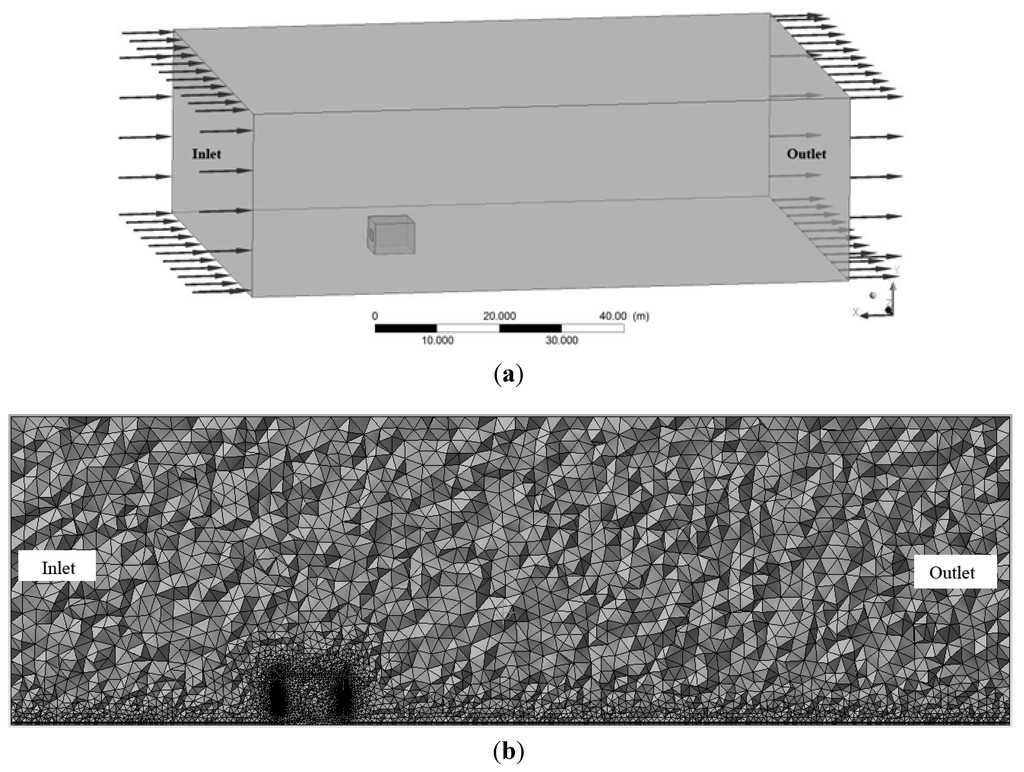
Figure 4.
(a) CFD domain; and (b) meshing for the single-cell room.
Figure 4.
(a) CFD domain; and (b) meshing for the single-cell room.

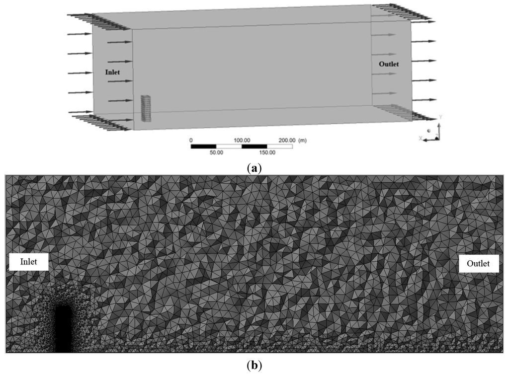
Figure 5.
(a) CFD domain; and (b) meshing for the multi-storey building.
Figure 5.
(a) CFD domain; and (b) meshing for the multi-storey building.

Figure 4, Figure 5 show the domain setup and meshing for the single-cell room and 12-storey building. The blockage ratio for both models is set at less than 2% to avoid blockage effects. The widths and heights of domain cross section for single-cell room are 71.5 m and 30 m, respectively, whereas, for 12-storey building are 400 m and 200 m, respectively. The cross section domain setup for 12-storey building is set to be similar to the wind tunnel facility in the experiment by Ismail [12].
The upstream distance for the inlet and windward facade of single-cell room and 12-storey building are 26 m and 60 m, respectively. The downstream distances for both models are set at 10 times the height of the buildings so that the airflows behind the buildings could fully develop. The wind profile is set differently for the two models; for the single-cell model, the wind speed for the whole surface of the inlet is set to 3 ms−1. For the 12-storey building, the inlet is set to have an atmospheric boundary layer (ABL) wind profile with a 0.28 power law mean speed wind profile similar to the wind tunnel setup used by Ismail. The wind speed at a height of 10 meters is set to 1 ms−1.
6. Results and Findings
6.1. Single-Cell Building
In this stage, the wind directions tested in the single-cell models are limited to 0°, 45° and 135° (models are rotated clockwise). The wind angles are selected based on the reference works by Givoni [11], which only tested these wind angles. Figure 6 shows outdoor and indoor airflows for four selected models that are obtained using Approach E.
Table 1 shows the ventilation prediction approaches together with the empirical models used for the ventilation prediction. The predictions are then used to validate the results obtained using Approach E (coupled CFD simulation). Equations (2) and (4) are used for validation because they include the effects of wind direction and façade modification. Although Approach B is the most appropriate approach for this small model, constraints in accessing appropriate facilities lead to the exclusion of this approach in the study.
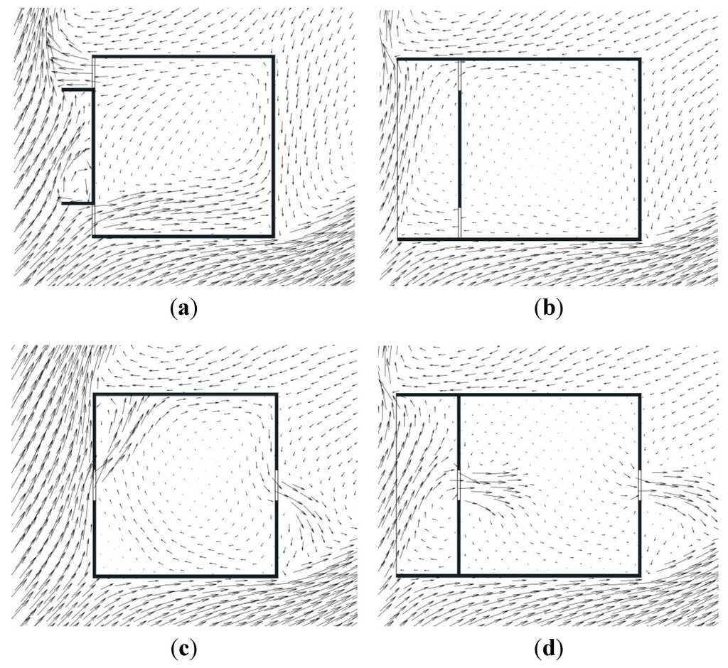
Figure 6.
Outdoor and indoor airflows taken at 2.5 m above floor level for (a) Model G03; (b) G05; (c) G06; and (d) G07 at 45° wind angle.
Figure 6.
Outdoor and indoor airflows taken at 2.5 m above floor level for (a) Model G03; (b) G05; (c) G06; and (d) G07 at 45° wind angle.
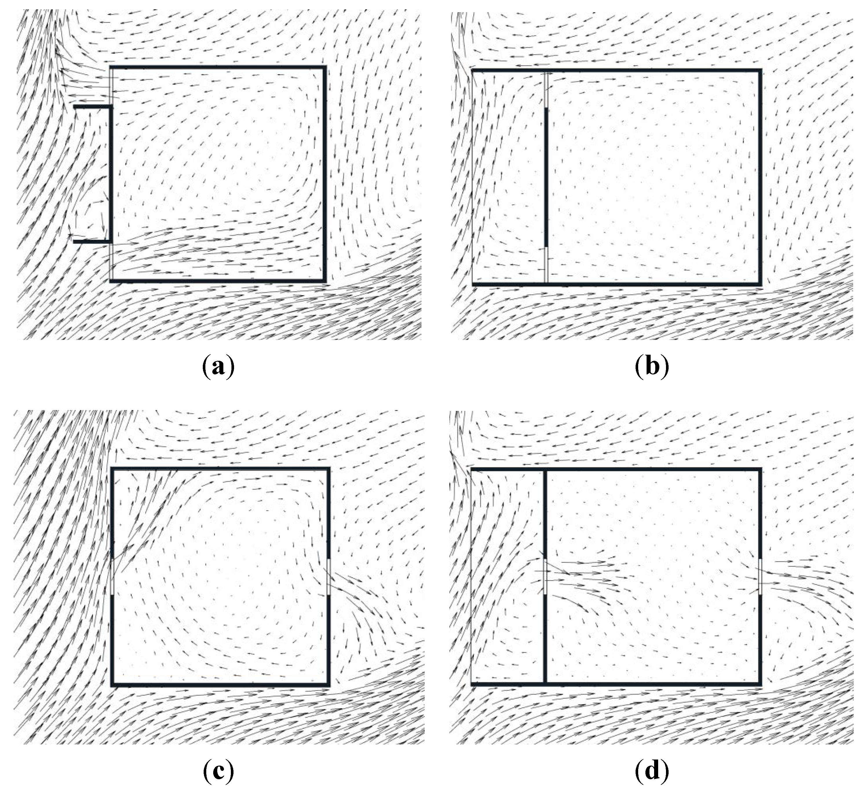
Table 1.
The approaches and empirical models used to predict ventilation performances to be compared to those predicted by Approach E.
| Model | Wind angles | ||
|---|---|---|---|
| 0° | 45° | 135° | |
| G01 | A (Eqn. 4) | A (Eqn. 4) | A (Eqn. 4) |
| G02 | A (Eqn. 4) | D (Eqn. 2) | D (Eqn. 2) |
| G03 | D (Eqn. 2) | D (Eqn. 2) | D (Eqn. 2) |
| G04 | D (Eqn. 2) | D (Eqn. 2) | D (Eqn. 2) |
| G05 | D (Eqn. 2) | D (Eqn. 2) | D (Eqn. 2) |
| G06 | D (Eqn. 2) | D (Eqn. 2) | D (Eqn. 2) |
| G07 | D (Eqn. 2) | D (Eqn. 2) | D (Eqn. 2) |
| G08 | A (Eqn. 4) | A (Eqn. 4) | A (Eqn. 4) |
Because earlier discussions suggests that the values for in Equation (2) is between 0.5 and 0.65 for an opening area less than 10% of façade area, this study uses a value of 0.65 for direct cross ventilation at 0° wind angle and 0.5 for all other wind angles. The pressure values used in Equation (2) are measured at the centre of the openings.
in Equation (2) is between 0.5 and 0.65 for an opening area less than 10% of façade area, this study uses a value of 0.65 for direct cross ventilation at 0° wind angle and 0.5 for all other wind angles. The pressure values used in Equation (2) are measured at the centre of the openings.6.1.1. Modification of Facade Treatment
Figure 7, Figure 8, Figure 9 show the comparison between the predictions by Approach E and the other approaches outlined in Table 1. Among all the single-cell models tested, the only models that are appropriate for the validation study are Model G01 and Model G06. This is because the facade treatment in these models is most appropriate for the application of empirical models for predicting ventilation performance. Based on the predictions for Model G01 and Model G06, we conclude that Approach E provides a sufficiently accurate prediction.
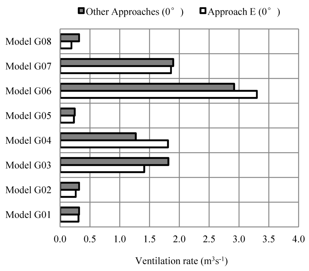
Figure 7.
Comparison of ventilation rates for Model G01 to Model G08 at 0° wind angle.
Figure 7.
Comparison of ventilation rates for Model G01 to Model G08 at 0° wind angle.


Figure 8.
Comparison of ventilation rates for Model G01 to Model G08 at 45° wind angle.
Figure 8.
Comparison of ventilation rates for Model G01 to Model G08 at 45° wind angle.
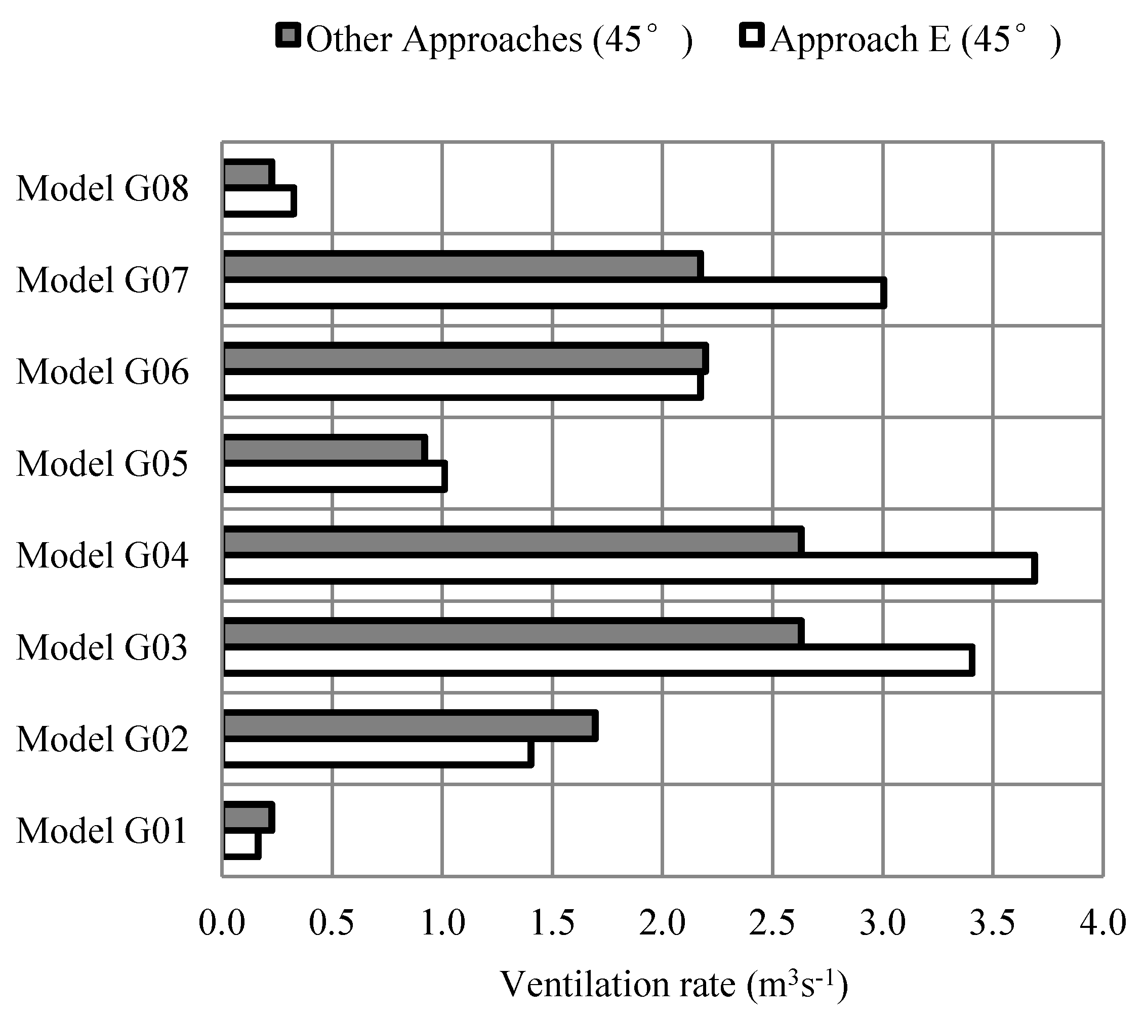

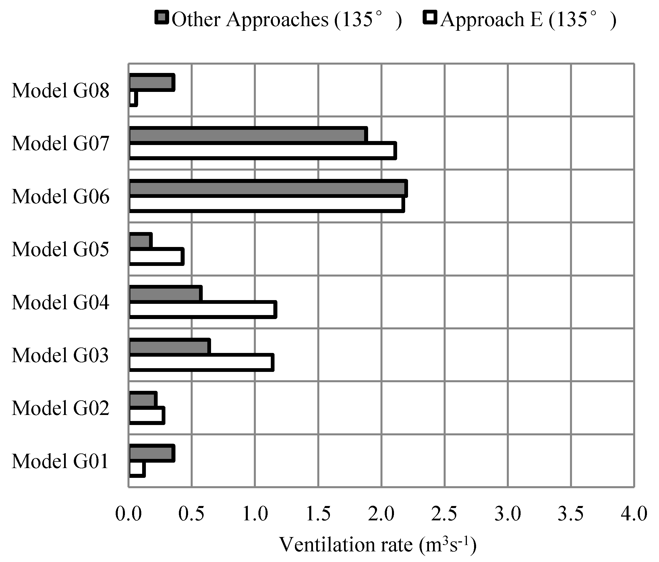
Figure 9.
Comparison of ventilation rates for Model G01 to Model G08 at 135° wind angle.
Figure 9.
Comparison of ventilation rates for Model G01 to Model G08 at 135° wind angle.
Other than Model G01 and G06, all of the models have some modifications on the building facades, including the introduction of horizontal or vertical protrusions that resemble overhang and wing wall, respectively. These protrusion elements modify the outdoor air flow characteristics close to the facades of the models and thus, could influence the ventilation performance of the models.
Although Figure 7 through Figure 9 show that Approach E can provide ventilation prediction trends similar to those predicted by the other approaches listed in Table 1, the findings suggest that Approach E could better predict the effects of the protrusion elements in comparison to other models. Two examples that support this finding are the comparisons between Models G01 and G08 and Models G02 and G04. In these examples, some contradictory predictions were found between Approach E and Approach D. This is a result of the limitation of the empirical models used in Approach D to take into account the effects of facade protrusions, such as an overhang and wing walls.
For example, with respect to the effects of wing walls in Model G03 and Model G04 at 45°, Figure 7 shows that Approach D predicts the ventilation performance for both models to be approximately similar, while Approach E predicts distinct differences in their ventilation performances. The predicted improvement due to the extended wing wall depth using Approach D is only 0.7% while Approach E predicted an improvement of 8.3%, which suggests a greater wind scoop effect in deeper wing walls.
Another example of the drawbacks of empirical models is the application of Approach A with Equation (1) for predicting models with a single opening and protrusion. This can be observed in Model G08 at all wind angles (see Figure 7, Figure 8, Figure 9). In reality, the introduction of a protrusion can affect the indoor ventilation performance and, thus, the ventilation performance of Model G08 is supposed to be different than that of Model G01. For example, at 0° wind angle, the ventilation rate for Model G08 is expected to be lower than that of Model G01 due to the buffer space created within the balcony. In this case, Approach E is able to capture these changes while the empirical model cannot.
6.1.2. Wind Direction and Ventilation Strategy
Wind direction also influences the accuracy of Approach E. The results shown in Figure 7 through 9 show that the worst prediction occurs for single-sided ventilated (SSV) rooms with openings located on the leeward side; thus, the prediction of ventilation performance in cross-ventilated rooms investigated in this study is generally better than that in SSV rooms. For all cases, the worst accuracy occurs in Model G08 at 135°. This can also be observed in Table 2. There two reasons for inaccuracy: CFD simulation with the standard k-epsilon model is weak on airflow predictions on the leeward side, and Equation (4) is less accurate due to the introduction of overhang and wing walls. The Equation (4) is derived by Larsen [14] based on experiment on a flat façade model.
Table 2.
The percentage of differences between the values predicted by Approach E as compared to those predicted using the approaches outlined in Table 1.
| Model | Wind angles | ||
|---|---|---|---|
| 0° | 45° | 135° | |
| G01 | 3.2 | 37.8 | 191.0 |
| G02 | 21.3 | 20.8 | 22.4 |
| G03 | 28.6 | 22.8 | 44.0 |
| G04 | 29.8 | 28.2 | 50.7 |
| G05 | 6.0 | 9.0 | 58.6 |
| G06 | 11.5 | 1.1 | 1.1 |
| G07 | 2.0 | 27.7 | 10.9 |
| G08 | 67.9 | 30.7 | 491.7 |
6.1.3. Prediction Accuracy
Generally, it can be observed that Approach E shows a ventilation performance trend similar to those of the other approaches in all models at all wind angles, including 135°. However, it is important to note the limitations and advantages of Approach E in comparison to the other approaches. An important limitation of Approach E is an inaccurate prediction for SSV rooms with an opening located on the leeward side. Another limitation of Approach E is that the accuracy of its ventilation prediction for single-sided ventilation is much less than that for cross ventilation (see Table 2).
The main advantage of Approach E as compared the other approaches is its ability to include the effects of facade modifications. Equation (2) does not include the effects of protrusion elements because it uses wind pressure data to calculate the ventilation rate, which does not describe the exact characteristics of outdoor airflow changes due to facade modifications. In Equation (4), the equation for the empirical model is derived from a complete wind tunnel experiment that only uses a flat facade.
6.2. 12-Storey Building
The CFD validation study in Stage 2 is divided into two parts: validation of wind pressure distributions and ventilation rates. Validation of the wind pressure distributions obtained from CFD simulations is important because it is necessary for Approach D. The following three wind angles are selected: 0°, 45° and 90°.
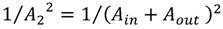
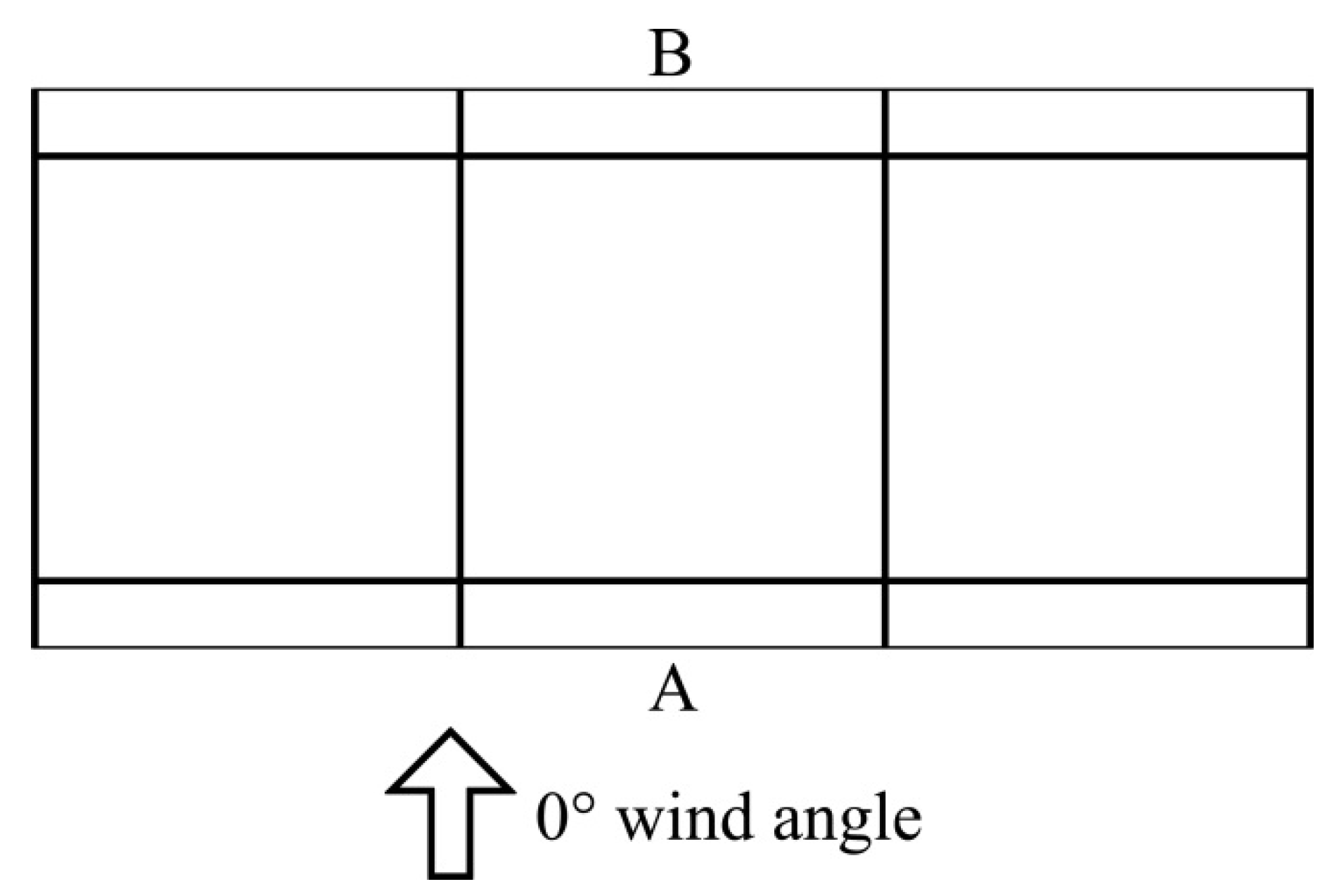
In the first part of Stage 2, two models without opening are simulated: a flat façade model (similar to Model S01, S03 and S05) and model with balconies (similar to Models S02, S04 and S06). Wind pressure values are measured at the middle of the windward and leeward facades of the middle units and compared with data from Ismail. Figure 10 shows the model with balconies at 0° wind angle and location of the pressure tapping along Line A (windward) and Line B (leeward). For 45° and 90° wind angles, the model is rotated clockwise. It is important to note that the wind pressure data obtained from the experiment by Ismail is in the form of pressure coefficients and the equation below is used to obtain the exact wind pressure values for this validation study.

Figure 10.
Wind direction (0°) and position of the tapping point for a model with a balcony.
Figure 10.
Wind direction (0°) and position of the tapping point for a model with a balcony.
6.2.1. Validation of Wind Pressure Distribution
Before proceeding with a discussion of the accuracy of CFD models for predicting wind pressure distributions, it is important to note that the flat facade model at 0° wind angle is used as a reference model for the CFD setup. The wind pressure distribution on the windward facade is used as a reference; therefore, the windward wind pressure accuracy for this case would be more accurate than the others.
Referring to Table 3, among all the wind angles investigated, CFD can most accurately predict wind pressures at the windward side. This is due to the simplicity of the airflow. The accuracy of wind pressure predictions on the leeward side is found to be low for all wind angles. These findings further support the findings in Stage 1, which suggests that Approach E is less accurate for predicting of airflow on the leeward side. Therefore, it can be assumed that if the ventilation rate is predicted using Approach E for the SSV high-rise model with an opening on the leeward side, the accuracy would be lower and could be misleading and, thus, it is excluded in the subsequent investigation.
Table 3.
The inaccuracies of CFD predictions of pressure distributions as compared to wind tunnel data.
| Facade treatment | Percentage of differences (%) | |
|---|---|---|
| Line A | Line B | |
| Flat (0°) | 5.3* | 37.8* |
| Balcony (0°) | 6.6* | 27.2* |
| Flat 45°) | 12.9^ | 37.9* |
| Balcony (45°) | 30.8^ | 21.1* |
| Flat (90°) | 27.7* | 13.0* |
| Balcony (90°) | 14.1* | 15.5* |
Note: * over-predicted; and ^ under-predicted.
The investigation of CFD predictions also suggests that if Equation (2) is used to predict the ventilation rate for a cross ventilated model, the predicted ventilation rate would be lower. Therefore, the use of Approach D may result in under prediction of ventilation performance due to over prediction of wind pressure on the leeward side. Thus, if this approach is to be adopted, the problem of over prediction on the leeward side needs to be addressed, for example, by replacing the standard k-epsilon turbulence model with a more accurate turbulence model, such as the Large Eddy Simulation (LES) [1,24,25].
6.2.2. Validation for Cross Ventilation Strategies
In the second part of Stage 2, the predicted ventilation rates using Approach E (coupled CFD simulation) are compared to those predicted using the other approaches. The approaches selected are as listed in Table 4 that includes Approach A, C and D. In Approach C, the wind pressure data obtained from the experiment by Ismail [12] is used. Equation (2) is used in Approach C and Approach D with a value of 0.65 for cross ventilation with 0° wind angle and 0.5 for all other wind angles. These values are selected because the porosity of the opening is less than 10%. Similar to the single-cell room, the pressure values to be applied in Equation (2) are measured at the centre of the openings.
value of 0.65 for cross ventilation with 0° wind angle and 0.5 for all other wind angles. These values are selected because the porosity of the opening is less than 10%. Similar to the single-cell room, the pressure values to be applied in Equation (2) are measured at the centre of the openings.
Table 4.
The approaches and empirical models used to predict ventilation performances to be compared to those predicted by Approach E.
| Model | Percentage of differences (%) | ||
|---|---|---|---|
| 0° | 45° | 90° | |
| S01 | C & D (Eqn. 2) | C & D (Eqn. 2) | - |
| S02 | C & D (Eqn. 2) | C & D (Eqn. 2) | - |
| S03 | - | A (Eqn. 1) | D (Eqn. 2) |
| S04 | - | D (Eqn. 2) | D (Eqn. 2) |
| S05 | - | D (Eqn. 2) | D (Eqn. 2) |
| S06 | - | D (Eqn. 2) | D (Eqn. 2) |
It is important to note that Approach A is less suitable for high-rise buildings because it is derived from and normally used for low-rise buildings, as described by Warren [17]. However, in this study, Approach A with Equation (1) is used for Model S03 at 45° under the assumption that each unit experiences the exact ABL wind speed at its particular height as the wind is flowing almost horizontally and parallel to the façade. This equation is used because no other appropriate empirical models for 45° wind angles are available. In Equation (1), the value of is set at 0.025, which is a commonly used value. The wind speeds used for Equation (1) calculations are the ABL wind speeds at the same height of the midpoint of the openings.
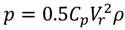
is set at 0.025, which is a commonly used value. The wind speeds used for Equation (1) calculations are the ABL wind speeds at the same height of the midpoint of the openings.Figure 11, Figure 12, Figure 13 show that the ventilation rates predicted for Model S01 at 0° by Approach E are acceptable, with an average differences percentage of 4.8% and 1.3% as compared with Approach C and D, respectively. Although the percentages show an acceptable level of agreement, Figure 11 shows that there are distinct differences in the ventilation performance distribution trend predicted by the three approaches for all units.

Figure 11.
Prediction of ventilation rates for Model S01 and Model S02 at 0°.
Figure 11.
Prediction of ventilation rates for Model S01 and Model S02 at 0°.
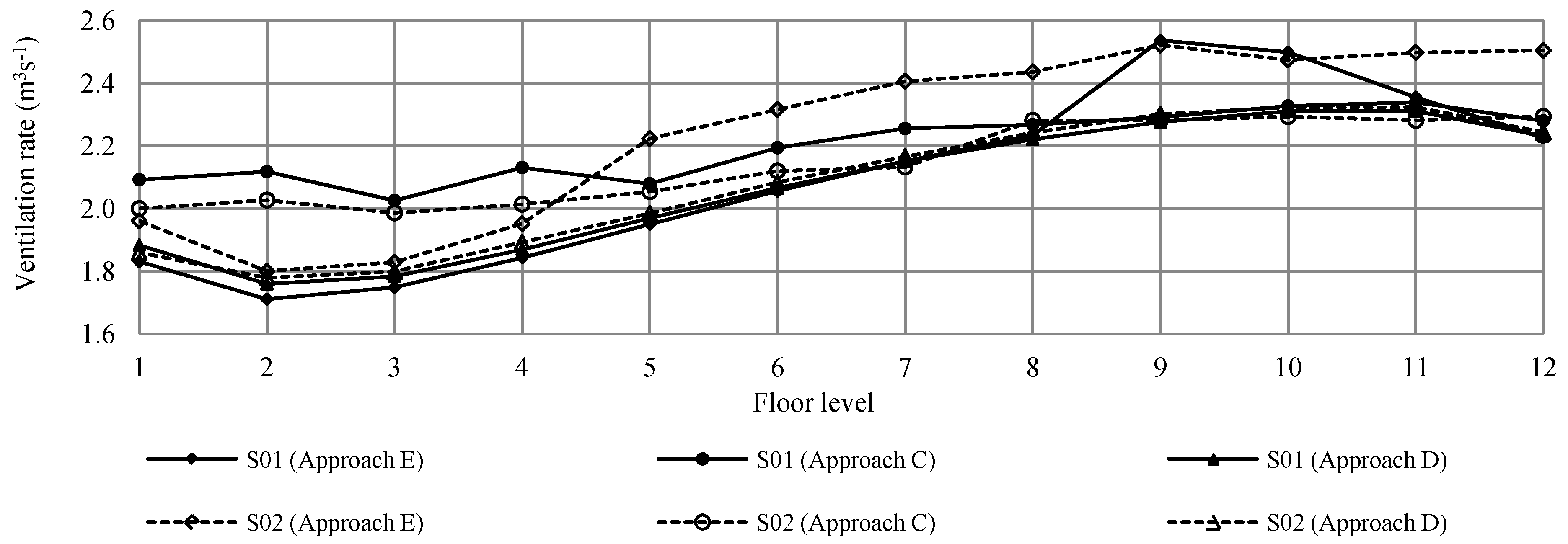
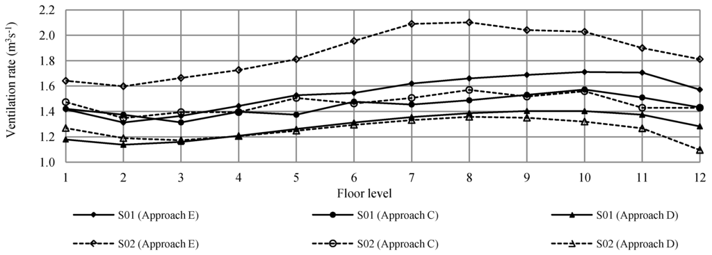
Figure 12.
Prediction of ventilation rates for Model S01 and Model S02 at 45°.
Figure 12.
Prediction of ventilation rates for Model S01 and Model S02 at 45°.


Figure 13.
Average ventilation rates (m3s−1) per unit for Model S01 and Model S02.
Figure 13.
Average ventilation rates (m3s−1) per unit for Model S01 and Model S02.
Using Approach C as a reference, Figure 11 shows that Approach D under-predicts for bottom units, while Approach E under-predicts the bottom units but over-predicts the units at levels 9 and 10. The reason for the under-prediction by Approach D is the inaccuracy of pressure distribution data predicted by CFD simulations with the standard k-epsilon model, especially for wind pressure data at the bottom of the leeward side. In the case of Approach E, one potential reason for the over-prediction at levels 9 and 10 could be that the discharge coefficient, , used in Approach C and D may not be accurate at levels 9 and 10 and should possibly have greater value due to the perpendicular wind angle. In the case of units located at level 7 and below, the reasons for-under prediction by Approach E are possibly a result of the limitations of CFD simulations. These limitations include inaccurate prediction at recirculation zones by the k-epsilon model. Another reason that may contribute to discrepancies for units located at level 7 and below between Approach E and others is inappropriate values being applied to Approach C and D where the value should be lower than 0.65 because the wind changes its direction as it hits the building and travels almost parallel to the windward facade.
, used in Approach C and D may not be accurate at levels 9 and 10 and should possibly have greater value due to the perpendicular wind angle. In the case of units located at level 7 and below, the reasons for-under prediction by Approach E are possibly a result of the limitations of CFD simulations. These limitations include inaccurate prediction at recirculation zones by the k-epsilon model. Another reason that may contribute to discrepancies for units located at level 7 and below between Approach E and others is inappropriate values being applied to Approach C and D where the value should be lower than 0.65 because the wind changes its direction as it hits the building and travels almost parallel to the windward facade.In the case of Model S02, Approach E predicts a greater ventilation rate from level 5 to the top of the building as compared to the other approaches. The predictions by Approach E suggest that this approach takes into account the effects of the balconies as a wind scoop, which could enhance the ventilation performance of the apartments. This effect is less obvious in the other approaches, especially in Approach D, which yields almost the same average ventilation rate predictions for flat facades as for facades with balconies (see Figure 13).
At 45°, Figure 12, Figure 13 show that the ventilation predictions made by Approach E are higher than those of Approaches C and D for both facade treatments and that a larger difference is observed in the model with balconies (Model S02). Similar to earlier findings at 0°, Approaches C and D do not show significant differences in the ventilation rate for flat facade and facade with balconies while Approach E does. With the introduction of the balconies, Approach C shows a ventilation improvement of 1.5% while Approach D shows a reduction of 2.4%. While Approach C and D show insignificant changes, Approach E shows a significant improvement with the introduction of the balconies (20.5%). The differences between the three approaches further prove that the Approach C and D are unable to account for the effects of the balconies in their predictions. This is due to the limitations of the pressure difference method (Equation (2)), which uses wind pressure values to describe outdoor airflow. Similar findings can also be observed in PS1 between Models G06 and G07 at 45°. At this wind angle, the introduction of balconies scoops the outdoor air into indoor spaces and the air travels almost parallel to the facade for flat facade models, which could reduce ventilation performance. The results also show that it is not appropriate to use a similar value for a flat facade and facade with balconies because the introduction of the balconies close to the openings could influence the effectiveness of the openings.
value for a flat facade and facade with balconies because the introduction of the balconies close to the openings could influence the effectiveness of the openings.Therefore, based on the validation study for cross ventilation, it can be concluded that the predictions made by Approach E are acceptable for this study. Approach E not only provides sufficiently accurate ventilation rate predictions but also provides acceptable predictions of changes in ventilation performance as a result of balconies. In the case of Approaches C and D, this validation study shows that these approaches are less suitable for predicting changes in ventilation performance with facade modifications close to an opening, such as in the case of balconies.
6.2.3. Validation of Single-Sided Ventilation Strategies
While the conclusion that Approach E is an appropriate and acceptably accurate approach for investigating the effects of balconies in cross-ventilated (CV) high-rise buildings, a further validation study is completed for single-sided ventilated (SSV) high-rise buildings. Figure 14, Figure 15, Figure 16 show the ventilation rate prediction results from various approaches.

Figure 14.
Prediction of ventilation rates for Model S03 to S06 at 45°.
Figure 14.
Prediction of ventilation rates for Model S03 to S06 at 45°.
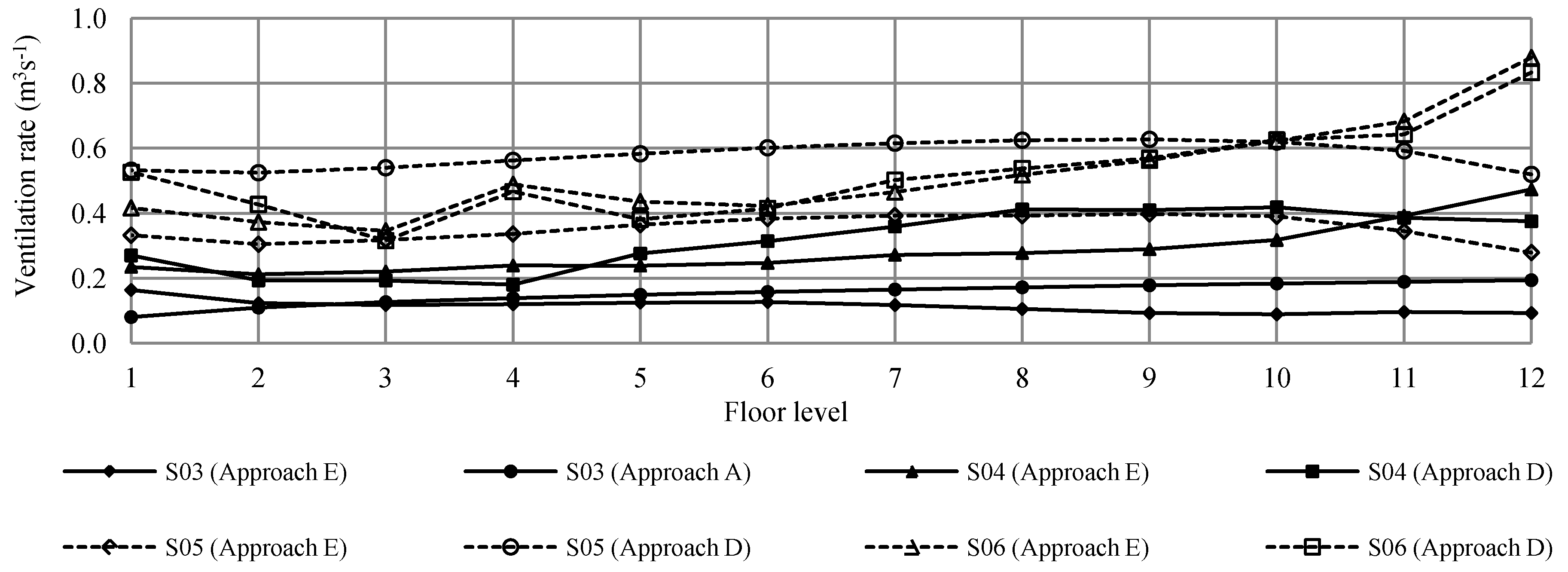
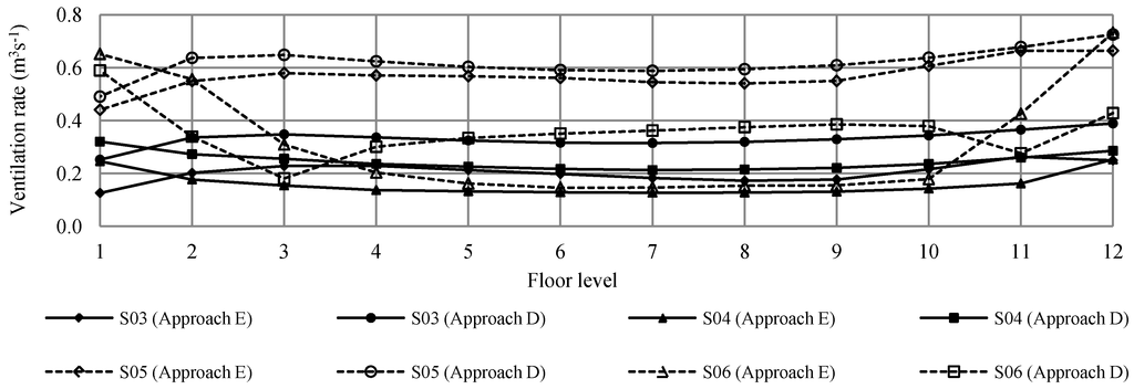
Figure 15.
Prediction of ventilation rates for Model S03 to S06 at 90°.
Figure 15.
Prediction of ventilation rates for Model S03 to S06 at 90°.
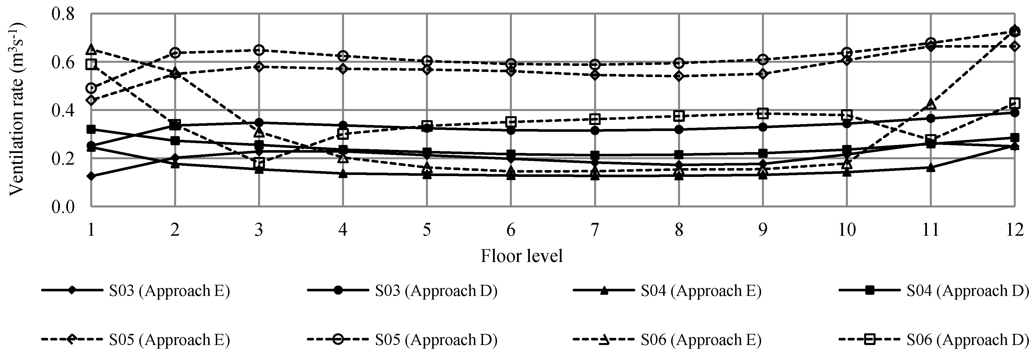

Figure 16.
Comparison of the average ventilation rates per unit for Model S03 to S06 using Approach E and Approaches A/D.
Figure 16.
Comparison of the average ventilation rates per unit for Model S03 to S06 using Approach E and Approaches A/D.
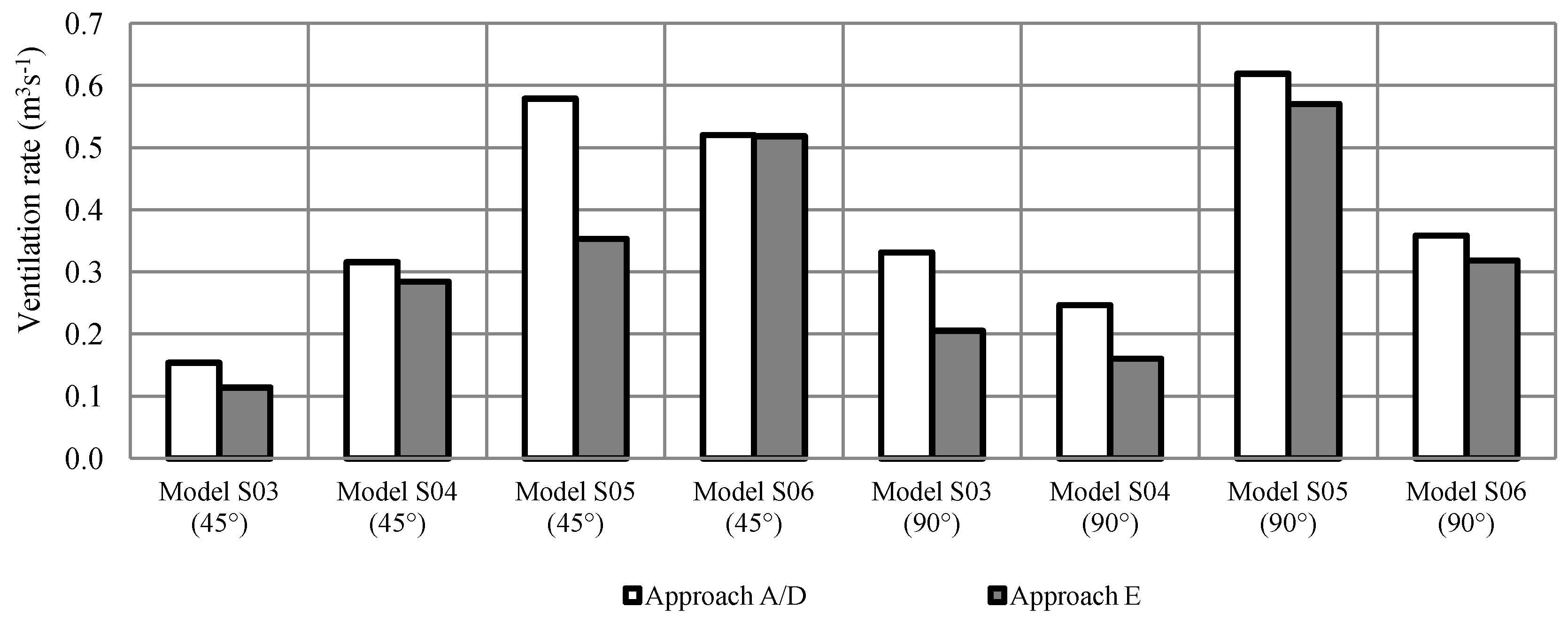
Figure 16 shows that the differences between the predictions made by Approach E and Approaches A/D can be significant, ranging from a mere 0.4% up to 39.0%. The average ventilation rate predicted by Approaches A and D are greater than those of Approach E.
Figure 16 shows that the ventilation predictions made by Approach E and Approaches A/D have a similar trend, except for the predictions for Model S05 and S06 at 45°. The predictions show contradictory results due to the introduction of balconies. Approaches A/D suggest that balconies reduce the average ventilation rate by 10.2%, while Approach E predicts that balconies lead to an increase in the average ventilation rate of 46.7%. The results predicted by Approach E are expected to result from two factors. First, at 45°, wind travels almost parallel to the flat building facade, creating a wind curtain just outside the openings, which could reduce ventilation performance. The second reason is that balconies with wing walls could acts as effective wind scoops that scoop the outdoor air into indoor air spaces. These contradictory results could represent a limitation of the applied pressure difference method (Approach D) to take into account the effects of the almost parallel wind flow relative to the facade of the building. Furthermore, the protruding elements act as a wind scoop, and the value of the discharge coefficient used in the method should vary based on the influences of the facade treatments on the effectiveness of the opening.
At 90°, both approaches show similar trends in the average ventilation rate performance, where the highest ventilation performance is found in Model S05 followed by Model S06, Model S03 and, finally, Model S04. Among these four models, significant prediction differences between predictions made by Approach E and Approach D are observed for Models S03 and S04 with difference percentages of 38.1% and 35.0%, respectively.
Although the average ventilation rate predictions of Approach E and Approaches A/D are different, it is found that the ventilation performance trends for all model configurations are generally similar except in cases in which external protrusions are introduced that could influence indoor ventilation performance. This further supports the findings for cross ventilation discussed earlier in this section and findings in the earlier investigation for single-cell rooms, which indicates that Approach E provides an acceptable prediction of airflow and is able to adequately compare the ventilation performance of various model configurations. Using Approach D, which uses the pressure difference method (Equation (2)), comparisons of various model configurations is difficult because of difficulties in deciding the values of the discharge coefficient, which is used to accurately describe various wind directions for different facade treatments.
which is used to accurately describe various wind directions for different facade treatments.7. Conclusions
This study suggests that the results obtained from the coupled CFD simulations (Approach E) are generally acceptable but are limited when predicting the ventilation performance of single-sided ventilation strategies with openings located on the leeward side of the building, where, in some cases, the percentage of differences against fully empirical models (Approach A) could be up to 191% as shown in Table 2 for Model G01, a flat façade model with a single opening. Therefore, the use of coupled CFD simulation for predicting ventilation performance in buildings is justified but with limitations. This study also suggests that for buildings with complex façade treatments, whether in single-cell rooms or multi-storey buildings, the coupled CFD simulation is a better ventilation prediction approach as compared to other approaches that use empirical models. This is due to the limitation of empirical models to account for the effects of protrusion elements, such as balconies and wing walls.
However, for a simple building façade with cross ventilation, a combination of CFD and empirical models (Approach D) would be a sufficient prediction model with reduced computational requirements. Furthermore, with application of Large Eddy Simulation (LES) or better Reynolds Averaged Navier-Stokes (RANS) equations turbulence models, the accuracy the combination of CFD and empirical models can further be improved.
Because the limitations of this study excluded physical models (Approach B), either small or full scale, from the validation study, it is important to conduct a study using physical models to understand the accuracy of the coupled CFD simulations in a complex building configuration. While it is possible to apply physical models for a single-cell room, this is not possible for a large-scale multi-storey building. An alternative for assessing the accuracy of the coupled CFD simulations in such a large-scale building would be taking measurements of an existing building. Additionally, future work on the application of improved RANS turbulence models or LES is vital to further understand the reliability of the coupled CFD simulations and to address the application of the standard k-ε turbulence models as discussed in this study.
References
- Chen, Q. Ventilation performance prediction for buildings: A method overview and recent applications. Build. Environ. 2009, 44, 848–858. [Google Scholar] [CrossRef]
- Mohamed, M.F.; King, S.; Behnia, M.; Prasad, D. An investigation on ventilation potential as a result of the provision of series of balconies on high-rise residential buildings using Computational Fluid Dynamics (CFD). Int. J. Environ. Cult. Econ. Soc. Sustain. 2011, 7, 197–209. [Google Scholar]
- Jiru, T.E.; Bitsuamlak, T. Application of CFD in modelling wind-induced natural ventilation of buildings—A review. Int. J. Vent. 2010, 9, 131–147. [Google Scholar]
- Prianto, E.; Depecker, P. Characteristic of airflow as the effect of balcony, opening design and internal division on indoor velocity: A case study of traditional dwelling in urban living quarter in tropical humid region. Energy Build. 2002, 34, 401–409. [Google Scholar] [CrossRef]
- Chow, W.K. Wind-induced indoor-air flow in a high-rise building adjacent to a vertical wall. Appl. Energy 2004, 77, 225–234. [Google Scholar]
- Wang, L.L.; Dols, W.S.; Chen, Q. Using cfd capabilities of contam 3.0 for simulating airflow and contaminant transport in and around buildings. HVAC&R Res. 2010, 16, 749–764. [Google Scholar]
- Wang, L.; Chen, Q. Applications of a coupled multizone-cfd model to calculate airflow and contaminant dispersion in built environments for emergency management. HVAC&R Res. 2008, 14, 925–939. [Google Scholar]
- Allocca, C.; Chen, Q.; Glicksman, L.R. Design analysis of single-sided natural ventilation. Energy Build. 2003, 35, 785–795. [Google Scholar]
- Ai, Z.T.; Mak, C.M.; Niu, J.L.; Li, Z.R. Effect of balconies on thermal comfort in wind-induced, naturally-ventilated low-rise buildings. Build. Serv. Eng. Res. Technol. 2011, 32, 1–16. [Google Scholar]
- Van Hooff, T.; Blocken, B. Coupled urban wind flow and indoor natural ventilation modelling on a high-resolution grid: A case study for the amsterdam arena stadium. Environ. Model. Softw. 2010, 25, 51–65. [Google Scholar] [CrossRef]
- Givoni, B. Ventilation Problem in Hot Countries. Reserach Report to the Ford Foundation, Technion; Building Research Station, Israel Institute of Technology: Haifa, Israel, 1968. [Google Scholar]
- Ismail, A.M. Wind-Driven Natural Ventilation in High Rise Buildings with Special Reference to the Hot Humid Climate of Malaysia; University of Wales College of Cardiff: Cardiff, UK, 1996. [Google Scholar]
- ASHRAE (American Society of Heating, Refrigerating and Air-Conditioning Engineers), 1997 Ashrae Handbook: Fundamentals; ASHRAE: Atlanta, GA, USA, 1997.
- Larsen, T.S. Natural Ventilation Driven by Wind and Temperature Difference; Aalborg University: Aalborg, Denmark, 2006. [Google Scholar]
- Awbi, H.B. Ventilation of Buildings; E & FN Spon: London, UK, 1991. [Google Scholar]
- Warren, P.R.; Parkins, L.M. Single-Sided Ventilation through Open Windows. In Thermal Performance of the Exterior Envelopes of Buildings; ASHRAE: Clearwater Beach, FL, USA, 1985; pp. 209–228. [Google Scholar]
- Warren, P.R. Ventilation through openings on one wall only. In International Centre for Heat and Mass Transfer Conference: Energy Conservation in Heating, Cooling and Ventilating Buildings; Hoogendorn, C.J., Afgar, N.H., Eds.; Hemisphere Publishing Corporation: Dubrovnik, Yugoslavia, 1977; Volume 1, pp. 189–209. [Google Scholar]
- Aynsley, R.M.; Melbourne, W.; Vickery, B.J. Architectural Aerodynamics; Applied Science Publisher Ltd.: London, UK, 1977. [Google Scholar]
- De Gids, W.; Phaff, H. Ventilation rates and energy consumption due to open windows: A brief overview of research in the netherlands. Air Infiltration Rev. 1982, 4, 4–5. [Google Scholar]
- Liddament, M.W. A Guide to Energy Efficient Ventilation; Air Infiltration and Ventilation Centre: Conventry, UK, 1996. [Google Scholar]
- Yoshie, R.; Mochida, A.; Tominaga, Y.; Kataoka, H.; Harimoto, K.; Nozu, T.; Shirasawa, T. Cooperative project for cfd prediction of pedestrian wind environment in the architectural institute of Japan. J. Wind Eng. Ind. Aerodyn. 2007, 95, 1551–1578. [Google Scholar] [CrossRef]
- Yim, S.H.L.; Fung, J.C.H.; Lau, A.K.H.; Kot, S.C. Air ventilation impacts of the “wall effect” resulting from the alignment of high-rise buildings. Atmos. Environ. 2009, 43, 4982–4994. [Google Scholar] [CrossRef]
- Cheng, C.C.K.; Lam, K.M.; Yuen, R.K.K.; Lo, S.M.; Liang, J. A study of natural ventilation in a refuge floor. Build. Environ. 2007, 42, 3322–3332. [Google Scholar] [CrossRef]
- Evola, G.; Popov, V. Computational analysis of wind driven natural ventilation in buildings. Energy Build. 2006, 38, 491–501. [Google Scholar] [CrossRef]
- Jiang, Y.; Chen, Q. Buoyancy-driven single-sided natural ventilation in buildings with large openings. Int. J. Heat Mass Transf. 2003, 46, 973–988. [Google Scholar] [CrossRef]
© 2013 by the authors; licensee MDPI, Basel, Switzerland. This article is an open access article distributed under the terms and conditions of the Creative Commons Attribution license (http://creativecommons.org/licenses/by/3.0/).