Abstract
Despite the aesthetic potential of free-form envelopes in large-scale public buildings, geometric interlacing complexity, ambiguous façade boundaries, and constructability translation gaps persist as systemic barriers. This study addresses these challenges through a Design Science Research (DSR) approach, developing a rule-based digital twin methodology that maintains parametric intelligence across the building life cycle. Implemented via a five-layer integrated framework, i.e., geometric, parametric, BIM, coordination, and fabrication, the methodology was validated through a revelatory case study of the Shenzhen Bay Culture Plaza. Results demonstrate 91.2% clash resolution prior to construction, 20.3 million RMB in cost savings (10.8% reduction), and 35.4% schedule compression, while preserving rule-based relationships into operational facility management. The study advances BIM theory by operationalizing life-cycle digital twins for non-standard geometries, offering a replicable framework for future special-shaped construction projects.
1. Introduction
Research Background and Motivation
Free-form and special-shaped envelopes have become defining features of contemporary large-scale public architecture, offering striking visual impact yet posing persistent technical challenges. Specifically, three systemic bottlenecks hinder their delivery: geometric interlacing complexity of non-standard surfaces leads to high fabrication error rates through manual stitching; ambiguous boundaries in Mayan-irregular stone façades (characterized by non-repetitive, sculptural geometries) cause cost overruns; and the constructability translation gap between sculptural geometry and industrialized construction results in schedule delays [1,2]. These challenges are exacerbated by the industry’s imperative toward energy conservation and industrial upgrading, where geometric deviations can amplify misalignments, triggering cascading costs.
While Building Information Modeling (BIM) and parametric design tools (e.g., Grasshopper) have emerged as essential technologies for complex geometries, current implementations remain fragmented. BIM predominantly serves post hoc clash detection rather than embedding construction logic into generative processes, whereas parametric tools excel at formal exploration but lack multi-disciplinary coordination capabilities [3,4,5]. This disconnection creates a translation gap where design intent and rule-based relationships are lost after handover, preventing the transition from static BIM models to living digital twins capable of supporting life-cycle facility management.
Addressing this gap, the present study adopts a Design Science Research (DSR) paradigm to develop a rule-based digital twin methodology. Through a five-layer integrated architecture, geometric abstraction, parametric rule engine, semantic data repository, collaboration protocol, and fabrication interface, the research maintains parametric intelligence from design through construction to operation. Using the Shenzhen Bay Culture Plaza as a revelatory case study, the research objectives are: (1) to establish a parametric-BIM workflow automatically resolving surface intersections with geometric fidelity; (2) to create a curvature-adaptive panel subdivision algorithm defining explicit boundaries for over 440,000 unique façade panels; and (3) to demonstrate life-cycle integration by outputting CNC-ready fabrication data and enabling IoT-supported facility management [6,7]. The contribution lies in providing a replicable, empirically validated framework that bridges the historical divide between architectural intent and industrial production.
2. Literature Review and Theoretical Framework
Despite significant advancements in digital design tools, three intertwined challenges continue to impede the effective delivery of free-form, special-shaped architecture. This section synthesizes recent developments in BIM and parametric design, positioning the proposed methodology within the current discourse and identifying critical research gaps.
2.1. BIM in Complex Geometric Design: The Interlacing Problem
The adoption of BIM for complex geometric design has accelerated in recent years, particularly in design optimization [8,9,10], CAD integration [11], and parametric design methodologies [12,13]. Studies such as Kociecki and Adeli’s shape optimization frameworks utilizing evolutionary algorithms, as well as Liu et al., who proposed generative algorithms for LCA optimization during the early design phase, demonstrate progress in design exploration and performance evaluation. However, a critical gap remains in the geometric interlacing phase—the automated generation of fabrication-ready, watertight solids from intersecting NURBS surfaces. Current methodologies often require manual intervention to resolve ambiguous intersections, a process documented to introduce error rates of 12–18% in panel extraction and fabrication data. This gap highlights the need for an integrated workflow that directly translates conceptual surfaces into constructible, clash-free assemblies [14,15,16].
2.2. BIM in Construction Coordination: The Boundary Ambiguity Problem
Research on multi-disciplinary coordination using BIM is extensive, establishing its value in clash detection and workflow integration [17,18]. However, conventional BIM coordination typically assumes planar or regularly curved building envelopes. For Mayan-irregular surfaces, explicit panel boundaries cannot be predefined, creating ambiguity in fabrication and installation. While parametric object libraries, such as those developed by Getuli et al., offer standardized components, they lack curvature-adaptive logic capable of managing the mass customization required for projects with hundreds of thousands of unique panels [19,20]. Specific digital construction technologies for special-shaped shell pipe structures and modular surfaces highlight the need for specialized BIM workflows to resolve these boundary ambiguities. Researchers have begun automating conceptual design using visual and generative programming, which can be extended to handle the complex boundary definitions of free-form envelopes. Recent advancements, such as the LLM-driven BIM-based DfMA method for free-form prefabricated buildings and the BIM-FEM model conversion method for special-shaped steel structures, offer promising pathways for integrating fabrication logic earlier in the design process. The absence of a rule-based system to dynamically generate explicit boundaries for non-standard geometries constitutes a significant limitation in current practice.
2.3. BIM in Life-Cycle Integration: The Constructability Translation Gap
The concept of the digital twin has gained considerable traction for enabling life-cycle data integration [21,22]. However, many implementations treat the BIM model as a static repository post-construction, failing to maintain its parametric intelligence into the operation phase. This results in a constructability translation gap, where the original design intent and logic are lost after handover, complicating maintenance, renovation, and facility management. To address this, automated and continuous BIM-based life cycle carbon assessment methods and integrated life-cycle management strategies are becoming essential for sustainable operation of complex structures. A true digital twin should preserve the rule-based relationships established during design, allowing for automated updates, performance simulation, and the generation of maintenance protocols directly from the model’s embedded logic [23,24]. Recent frameworks propose integrating BIM with data mining and AI to transform static models into intelligent management systems, enabling advanced project management and predictive maintenance.
2.4. Research Gap and Positioning
Synthesizing the literature reveals several persistent gaps that this study aims to address:
Integrated Life-Cycle Frameworks: A lack of methodologies that maintain active parametric intelligence from initial design through construction to long-term facility management [25,26].
Quantitative Validation in Mega-Projects: Limited empirical, performance-based evidence validating parametric-BIM workflows in real-world, large-scale projects with extreme geometric complexity [27]. While specific applications exist for historical building components based on point cloud data and digital fabrication processes in South Korea, a generalized rule-based methodology for life-cycle delivery remains underexplored.
Rule-Based Digital Twins for Free-Form Envelopes: The absence of a specifically tailored rule-based digital twin methodology to manage the unique challenges of free-form, special-shaped building envelopes.
Comparative Performance Analysis: Insufficient comparative studies demonstrating the measurable improvements (in cost, schedule, accuracy) of integrated parametric-BIM approaches over conventional methods.
Although BIM, IoT, and GIS integration is being explored for resource monitoring, and comparisons between complex and simple buildings highlight implementation benefits, there is still a lack of holistic frameworks that combine these elements specifically for free-form architectural envelopes.
This research directly addresses these gaps by proposing and validating a comprehensive, rule-based digital twin methodology. Using the Shenzhen Bay Culture Plaza (188,000 m2) as a revelatory case study, it demonstrates a workflow that not only resolves geometric and coordination challenges but also provides quantitative evidence of its efficacy across the building life cycle.
3. Research Methodology
3.1. Design Science Research Paradigm
Rooted in the information systems discipline, DSR distinguishes itself from behavioral science by focusing on the creation and evaluation of innovative artifacts rather than merely describing or explaining existing phenomena. Following Hevner et al.’s (2004) seminal framework, this study positions the rule-based digital twin as a socio-technical artifact designed to solve the organizational problem of knowledge discontinuity in complex architectural delivery [28]. The methodology adheres to the dual imperatives of relevance and rigor: the relevance cycle ensures the artifact addresses the three identified industry bottlenecks, while the rigor cycle grounds the research in existing BIM ontology and complexity theories [29].
Building upon this theoretical foundation, this study adopts a Design Science Research (DSR) methodology to develop, implement, and evaluate a novel rule-based digital twin artifact for the life-cycle delivery of free-form architecture [30,31]. The DSR paradigm is appropriate as it focuses on creating and assessing innovative artifacts designed to solve identified organizational problems—in this case, the three persistent bottlenecks in delivering complex, free-form, special-shaped envelopes. The research progresses through iterative cycles of artifact building, demonstration, and evaluation within the real-world context of the Shenzhen Bay Culture Plaza project (Figure 1).
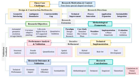
Figure 1.
Research framework.
3.2. Revelatory Case Study Design
A single, revelatory case study strategy is employed to provide an in-depth, empirical investigation of the proposed methodology [32,33]. The Shenzhen Bay Culture Plaza was selected as the case based on pre-defined criteria that ensure it represents an extreme and information-rich context for studying the targeted challenges. The selection criteria required a project exhibiting: (1) extreme geometric interlacing of multiple free-form volumes; (2) ambiguous façade boundaries requiring mass customization of over 400,000 unique stone panels; and (3) significant sculptural-to-industrial translation challenges for fair-faced concrete shells. This 188,000 m2 project, comprising eight distinct “stone-cluster” buildings, satisfies all criteria and serves as the primary demonstration and validation site for the workflow artifact.
3.3. Integrated Parametric-BIM Workflow
The core artifact is an integrated parametric-BIM workflow structured across five synchronized layers. The Geometric Layer hosts master NURBS surfaces in Rhino. The Parametric Rule Layer encodes constraints via Grasshopper scripts. The BIM Data Layer utilizes parameter-enriched Revit families for semantic information. The Coordination Layer employs a cloud platform for real-time multi-disciplinary collaboration. The Digital Fabrication Layer auto-generates CNC-ready data [34,35]. Governance is provided by a parametric rule set organized into three categories: Geometric Rules (e.g., curvature limits, subdivision logic), Material Rules (e.g., life-cycle assessment coefficients, cost libraries), and Construction Rules (e.g., formwork panelization, setting-out coordinates).
3.4. Implementation and Validation Framework
Artifact implementation follows a four-phase framework. Phase 1: Data quality analysis verifies geometric completeness and performs initial clash detection. Phase 2: Model integration establishes bidirectional Revit–Rhino links via Rhino.Inside.Revit (v1.0) for data synchronization. Phase 3: Integrated design deepening executes detailed development—boundary definition, structural thickening, MEP integration—driven by parametric rules. Phase 4: Model-drawing output generates final deliverables: site-coordinate-transformed geometry, multi-LOD models, and fabrication/positioning data [36,37]. A custom Grasshopper battery library (47 components) operationalizes the rules, with tools for surface analysis, drainage simulation, and structural integration.
3.5. Evaluation Strategy
Evaluation comprises three validation cycles aligned with DSR. Design phase validation involved 50+ iterative performance analyses (structural, drainage, quantity take-off) tracking Key Performance Indicators (KPIs) like geometric fidelity and clash resolution. Construction-phase validation stress-tested outputs via 4D BIM simulation and as-built scanning, verifying installation accuracy and workflow efficiency. Operation-phase validation integrated IoT data post-occupancy to assess digital twin utility in facility management and predictive maintenance [24,38]. This multi-cycle approach provides quantitative evidence of artifact efficacy across the building life cycle.
4. Case Study: Shenzhen Bay Culture Plaza
4.1. Project Overview
The Shenzhen Bay Culture Plaza, encompassing the Shenzhen Creative Design Museum and the Shenzhen Science and Technology Life Museum, constitutes one of Shenzhen’s “Top Ten Cultural Facilities.” Strategically positioned within the core cultural belt of Houhai Central District, it serves as a window projecting the innovative and creative urban image of the Houhai area. Its overarching mission is to function as a creativity hub integrating design and science. Upon completion, the complex operates as an open, integrated, natural, and future-oriented venue that fuses creative and design exhibitions, art and science exchanges, and future-oriented life experiences (Figure 2).
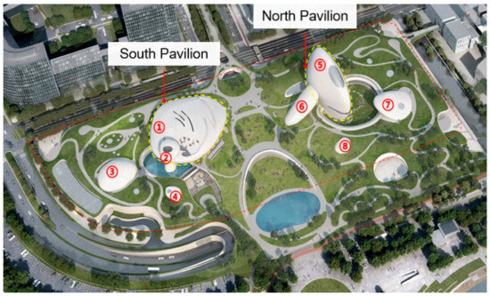
Figure 2.
General layout plan.
The project occupies a planning land area of 50,887.59 m2 and delivers a total construction area of approximately 188,000 m2. Of this total, the above-ground construction area equals 52,249.17 m2, while the below-ground construction area is 135,585.4 m2, inclusive of 36,158.51 m2 of civil-defense works. The south pavilion reaches a height of approximately 31 m; the north pavilion rises to approximately 52 m. The substructure comprises three basement levels; the superstructure encompasses six above-ground floors (with partial mezzanines). Table 1 summarizes the building functions and Table 2 presents key project data [39,40].

Table 1.
Building functions and characteristics.
Table 2.
Key project data.
This project was selected as a revelatory case study due to its extreme geometric complexity and life-cycle data availability, aligning with the methodological approach outlined in Section 3.2.
4.1.1. Architectural Concept and Design Intent
Anchored by the design concept of a naturally growing stone cluster, the buildings are meticulously arranged to evoke an organically emergent assemblage of rocks, thereby endowing the site with a primordial yet surreal sense of nature. This approach not only recalls the carefully composed rockeries of classical Chinese gardens but also establishes a distinctive integration of culture and nature within the contemporary urban landscape. In lieu of conventional glass curtain walls, the project employs a natural stone curtain wall system integrated with undulating green landscapes to generate a surreal visual effect.
The design intent prioritized three architectural qualities: (1) formal continuity between building and landscape, (2) material authenticity through exposed fair-faced concrete and natural stone, and (3) spatial complexity that challenges conventional orthogonal design. These qualities simultaneously created the three technical bottlenecks that this research addresses.
4.1.2. Spatial Typologies, Design Challenges and Parametric Responses
The architectural spaces are classified into three principal typologies, each presenting distinct design challenges (Figure 3):
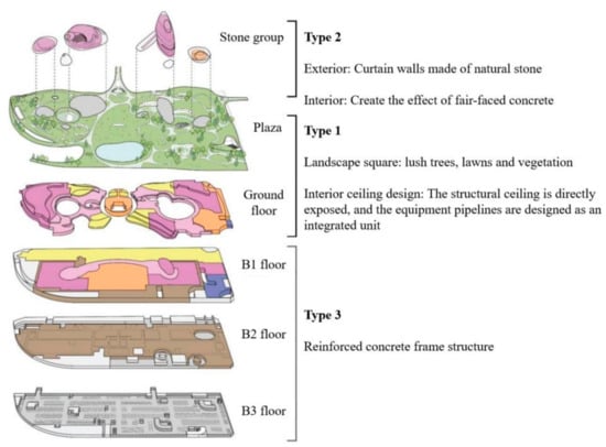
Figure 3.
Spatial Typologies: Type 1—continuous undulating park roof; Type 2—irregular stone clusters; Type 3—conventional RC frame system.
Type 1 comprises the continuous undulating park roof, which extends from the coastal edge toward the urban side and is planted with diverse lawns, shrubs, and dense trees to create a large-scale public activity space. This typology faces critical issues of structural complexity due to undulating elevations and vegetation loading that create non-uniform load paths, requiring parametric load analysis. Additionally, complex intersections between structure and building-service pipelines beneath the roof demand careful MEP coordination, while continuous curved surfaces necessitate sophisticated rainwater management systems. Fair-faced concrete Miller beams tracing these undulations further require precise formwork design. The roof employs complex structural configurations with spans exceeding 30 m in certain zones, and the parametric relationship between roof geometry, structural depth, and MEP routing represents a primary coordination challenge [41].
Type 2 encompasses the irregular stone clusters, both internal and external, characterized by an exterior stone curtain wall assembled from tightly jointed natural stone panels and an interior exhibition hall executed in cast-in-place fair-faced concrete. The outer curtain wall surface comprises stone strips with visible joints, introducing critical design issues including subdivision of unit panels for heavy curtain walls, which total 440,000 panels (Table 3). The zig-zag jointing patterns between panels require curvature-adaptive detailing [19,20], while installation logistics for lifting and placing heavy stone panels on irregular surfaces present significant challenges. Waterproofing of irregular curtain wall geometries without compromising visual appearance must be addressed, along with structural safety assessment against stone panel detachment under wind and seismic loads. The Mayan-irregular nature of these surfaces means that no two panels are identical, necessitating mass customization approaches.
Table 3.
Stone cluster panel sizes and quantities.
Type 3 comprises conventional reinforced concrete frame systems with large functional spaces, which, while well understood, still require BIM coordination for MEP integration and serve as a baseline for comparing workflow efficiency.
Collectively, these design challenges established a comprehensive testbed spanning from conception to operation. The project was completed and commenced operation in 2023. Its integrated Internet of Things (IoT) sensor network, linked to the digital twin model, provides a continuous stream of real-world data, forming the foundational dataset for the operational phase validation.
4.2. Implementing the Workflow Artifact
4.2.1. Workflow Architecture
A hybrid Rhino–Grasshopper–Revit environment was established as the technical core of our methodology. Grasshopper served as the parametric engine, encoding design rules and generating geometry variants, while Revit acted as the federated BIM repository, hosting discipline-specific models and enabling clash detection. Custom C# 13 and Python 3.13.12 scripts, compiled as Grasshopper “batteries,” automated geometry translation, quantity take-off, and clash-matrix updates. A cloud-hosted Model Coordination space synchronized multi-disciplines in real-time, while APIs pushed clash reports back to Grasshopper for automatic rule recalibration. Furthermore, custom APIs were configured to automatically push clash reports generated by the cloud coordination platform back to the Grasshopper parametric engine. This closed-loop feedback mechanism enabled real-time recalibration of the design rules based on multi-disciplinary coordination insights, embodying the intelligent, self-optimizing capability of the workflow (Figure 4).
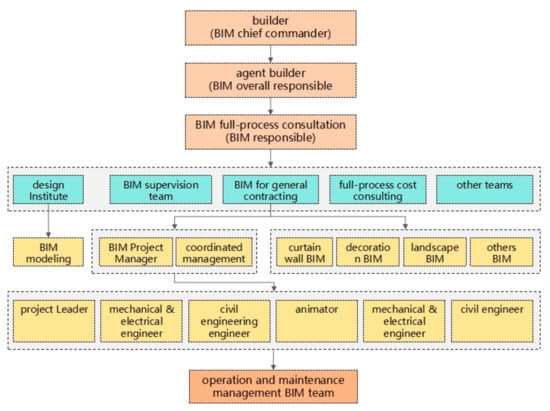
Figure 4.
Multi-professional collaboration framework.
The workflow operates through five synchronized layers that function as an integrated system. The Geometric Layer involves Rhino hosting the master NURBS model, with Grasshopper scripts generating all derived geometry. The Parametric Rule Layer encodes design constraints, optimization objectives, and fabrication logic. The BIM Data Layer consists of Revit models enriched with parameters for quantity, cost, schedule, and performance. The Coordination Layer provides a cloud platform enabling real-time multi-disciplinary collaboration. Finally, the Digital Fabrication Layer produces CNC-ready outputs for formwork, rebar, and stone panels (Figure 5).
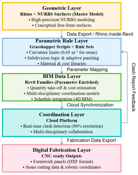
Figure 5.
Integrated parametric-BIM workflow architecture.
4.2.2. Parametric Rule Set Development
The parametric rule set, which serves as the central “artifact,” comprises three categories of rules that work in concert.
Geometric Rules establish curvature thresholds, setting maximum allowable Gaussian curvature for stone panels at 0.05 m−2 (equivalent to radius of curvature ≥ 20 m) and for fair-faced concrete at 0.10 m−1 (radius ≥ 10 m) to ensure constructability (Notes: m−2 represents Gaussian curvature (product of principal curvatures) and m−1 represents mean curvature).
These rules also include an adaptive panel subdivision algorithm that balances panel size uniformity with curvature variation, thereby minimizing cutting waste. Additionally, drainage slope constraints enforce a minimum 2% slope for roof surfaces with parametric adjustment for soil-cover thickness, while structural-grid alignment tolerances limit maximum deviation between architectural surface and structural grid to ±50 mm to avoid rework.
Material Rules assign embodied carbon coefficients to each material type, including C40 concrete, local granite, and structural steel, for real-time life-cycle assessment calculations. Unit-cost libraries link material and labor costs to geometric parameters, enabling automatic cost estimation during design iterations. Durability parameters are also incorporated, using weathering coefficients for exterior stone based on exposure orientation and local climate data.
Construction Rules enable automatic generation of CNC-ready formwork meshes with panelization optimized for standard plywood sheet sizes of 1220 × 2440 mm. They also generate XYZ coordinates for every critical point, exported in machine-readable format for automated layout using robotic total stations, and create parametric rebar models that generate cut-and-bend schedules.
4.2.3. Deepening Design Workflow for Complex Curved Surfaces
The detailed procedural framework for curved surface application design comprises four sequential phases.
Phase 1 involves data quality analysis before model refinement, which includes completeness verification to check for missing surface patches or edge discontinuities, exposed-edge analysis to identify surfaces requiring edge treatment or joint detailing, fair-faced concrete boundary confirmation to validate boundaries between exposed and hidden concrete surfaces, and initial clash detection for gross geometric errors.
Phase 2 focuses on model integration between Revit and Rhino using the Rhino.Inside.Revit plugin, which enables automatic synchronization of geometric changes, parameter mapping between Grasshopper and Revit families, and version control with change tracking.
Phase 3 encompasses integrated design deepening, which includes precise definition of all material transitions through boundary deepening, reverse thickening of shell surfaces based on structural requirements, 3D chamfer design for all edges to ensure constructability, parametric optimization of structural connections, detailed modeling of hanging stone panels including anchors, precise openings for ducts, pipes, and conduits through MEP reservation detailing, and management of intersections between fair-faced concrete and other disciplines through interface coordination.
Phase 4 addresses model-drawing output, which includes coordinate system transformation, where all geometry is transformed from the design coordinate system (local Rhino origin) to the site coordinate system by applying transformation matrices for rotation, translation, and scaling, verified through survey control points with generation of transformation reports for contractor validation. Model-dimension optimization employs parametric dimensioning where key control dimensions are linked to geometric parameters, 3D annotation with spatial dimension strings that update automatically with geometry changes, and explicit tolerance bands for field verification. Lightweight export decimates model geometry for field use at various Level of Detail (LOD) specifications—LOD 200–300 for overall coordination, LOD 400 for fabrication drawings, and LOD 500 for as-built documentation—with export formats including IFC, DWG, and CNC-ready DXF. Finally, positioning information extraction automatically generates setting-out coordinates at XYZ points for robotic total stations (every 2 m on critical edges), unique panel IDs for each stone panel linking to fabrication database, installation vectors as normal vectors for each panel to guide installation angle, and quality control points for post-installation survey verification.
These outputs provide precise guidance for construction implementation, reducing field measurement time by 60% and rework by 85%.
4.2.4. Custom Grasshopper Battery Library Development
To implement the workflow, a custom Grasshopper battery library was developed containing 47 specialized components that address various aspects of the project.
The library includes surface analysis tools for curvature analysis, developability testing, and panel subdivision. It also features structural integration components for grid alignment, load path visualization, and structural form finding. Fabrication tools are incorporated for formwork panelization, rebar detailing, and stone panel optimization. Coordination tools enable clash detection, version comparison, and change propagation. Finally, performance tools provide daylight analysis, drainage simulation, and carbon calculation.
Each battery was documented with XML metadata including input/output specifications, algorithm descriptions, and validation test results. Crucial components within this library, such as the ‘MayanSubdivider’ (for curvature-adaptive facade paneling) and the ‘DrainageTracer’ (for roof drainage path analysis), were instrumental in conducting the performance-based parametric analyses.
4.3. Performance-Based Parametric Analysis
This section concretely demonstrates the design phase validation cycle (Section 3.5). Through over 50 generative design iterations utilizing the parametric toolset described in Section 4.2.4, performance-driven analyses were conducted across seven key domains [42,43,44]. These analyses directly tracked KPIs such as geometric fidelity and clash resolution, providing iterative feedback for design refinement.
4.3.1. Parametric Roof Structure Analysis
The original irregular roof was parameterized to establish explicit relationships with the structural column grid. Without altering the overall grass-slope roof morphology, BIM parametric tools deployed during the design phase analyzed spatial coupling between roof and column grid, ensuring precise alignment (Figure 6).
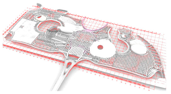
Figure 6.
Parametric roof-structure-driven deepening.
The parametric model enabled real-time grid adjustment, where structural column positions automatically adjusted to follow roof undulations. Load path optimization was achieved by parametrically mapping dead loads from soil cover of variable thickness (0–3 m) and live loads from public activity to structural elements. Clear-height verification was automated, checking minimum clear heights of 4.5 m for public zones and 3.5 m for service areas.
4.3.2. Structural Seismic Review
Owing to the complexity and irregular warping of the structural configuration, the BIM environment was linked to structural analysis software (ETABS v22.1.0) during the design phase. Three-dimensional spatial information was imported for finite-element simulation, successfully passing the structural over-limit seismic review (Figure 7).
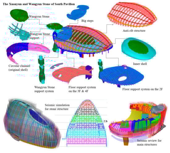
Figure 7.
Structural seismic review and finite-element simulation.
The parametric workflow enabled geometry-to-analysis integration through direct Grasshopper-to-ETABS data exchange via the GGWin plugin. Multi-modal analysis allowed simultaneous evaluation of seismic, wind, and gravity loads. Real-time feedback meant analysis results (stress concentrations, displacement magnitudes) automatically highlighted problematic geometric regions in the Rhino model. An optimization loop enabled parametric adjustment of shell thickness (variable 300–800 mm) and rib spacing (1.2–2.0 m) to achieve target performance metrics. The structure achieved a seismic performance rating of “excellent” with maximum inter-story drift ratios of 1/550 under design basis earthquake (DBE) and 1/300 under maximum considered earthquake (MCE).
4.3.3. Roof Elevation Sorting and Drainage Analysis
Grasshopper scripts located elevations of the grass-slope roof parametrically. Structural height, MEP clearances, soil-cover thickness, and drainage organization were sorted and adjusted according to net-height requirements. Three-dimensional visualization guided subsequent construction (Figure 8).
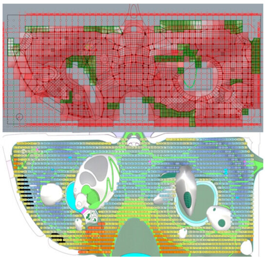
Figure 8.
Parametric positioning of free-form, special-shaped roof elevations.
Drainage analysis included rainwater slope verification, ensuring minimum 2% slope was maintained across all roof surfaces. Gutter placement involved parametric identification of valley lines for drainage gutter placement. Raindrop simulation used particle tracing to verify water flow paths and prevent ponding. Hydraulic calculation applied Manning’s equation to size drainage components. The analysis identified 23 critical drainage nodes requiring enhanced waterproofing details.
4.3.4. Multi-Disciplinary Quantity Calculation
Given the three-dimensional irregular geometry, conventional two-dimensional drawings cannot yield accurate quantities. Grasshopper was employed to directly extract the area of each irregular curved surface within the model, classifying and summarizing areas for cost estimation (Figure 9).
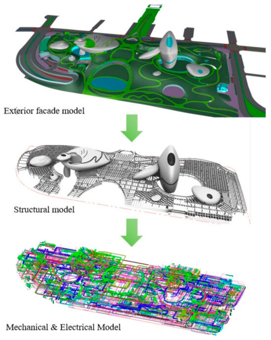
Figure 9.
Multi-disciplinary model-integrated quantity calculation.
The automated quantity take-off achieved surface area accuracy of ±0.5% compared to manual measurement of as-built scan, a 95% reduction in quantity calculation time (from 3 weeks to 8 h), and enabled lump-sum contracts with <2% variation orders. Total calculated quantities included 18,450 m3 of fair-faced concrete, 16,735 m2 of stone panels, 42,300 m2 of formwork contact area, and 2850 tonnes of reinforcement.
4.3.5. Curtain Wall Curvature and Texture Analysis
A salient feature is the variable curvature of the stone-like curtain wall across different locations. Curvature and orientation subdivision were undertaken; curvature at each location was analyzed using BIM parametric tools, and stone joint orientations were adjusted in response to local curvature, aligning joint directions as closely as possible with the direction of minimum curvature (Figure 10).
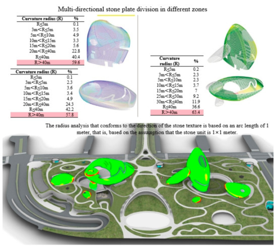
Figure 10.
Parametric curtain wall curvature analysis.
The curvature analysis revealed that 12% of façade area exceeded the 0.05 m−2 threshold, requiring special 3D-machined panels. Panel subdivision optimization through joint orientation alignment reduced average stone-cutting thickness by 18%, saving 340 m3 of stone material (≈1.2 million RMB). Texture analysis ensured staggered, seemingly random façade composition while maintaining twelve standardized panel-unit types for economic efficiency (Figure 11)
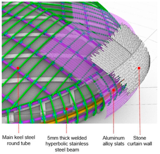
Figure 11.
Curtain wall texture analysis.
4.3.6. Water-Collection Analysis
To maintain a visually crisp stone curtain wall appearance, the project adopted an internal joint drainage structure. During the design phase, joint texture and water-collection efficiency were simulated. Various stone joint types were studied, and dripping test simulations were executed (Figure 12).
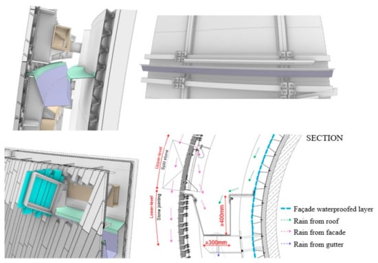
Figure 12.
Curtain wall water-collection analysis.
The analysis involved elevation contour mapping, where raindrop simulations were overlaid upon elevation contour lines to trace water flow. Innovative drainage geometry introduced a “direction line” concept that replaced conventional drainage gutters, using stepped interception gutter geometry. Efficiency validation achieved 98% water-collection efficiency during a 100-year storm event. Visual–functional unification was maintained, as the solution preserved the crisp joint appearance while ensuring functional drainage.
4.3.7. Clear-Height and Traffic Organization Analysis
Three-dimensional verification of in-buiding routes confirmed that MEP services, structural depths, and soil-cover thickness in critical zones satisfied clear-height standards, maintaining minimum public clear heights of 4.5 m across all exhibition zones and 2.8 m minimum in-service corridors for maintenance access. Computer simulations of vehicle trajectories and pedestrian flow verified traffic smoothness and crowd distribution in high-density areas, ensuring all emergency egress routes comply with the 60 m travel distance requirement to exits while accessibility ramp slopes were maintained below 8% for universal access (Figure 13).
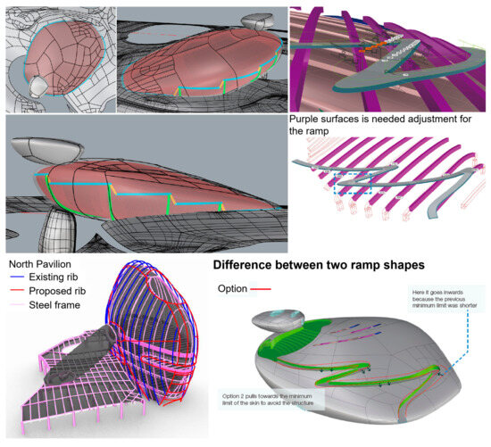
Figure 13.
Ramp shapes verification and traffic simulation.
5. Results and Discussions
The rule-based digital twin methodology achieved 91.2% clash resolution prior to construction and generated 20.3 million RMB in cost savings (Table 4 and Table 5). The curvature-adaptive algorithm successfully defined explicit boundaries for over 440,000 unique stone panels, eliminating boundary ambiguity post-occupancy IoT integration validated life-cycle intelligence preservation, distinguishing this from static BIM repositories. These results demonstrate that embedding parametric rules across the five-layer architecture bridges the constructability translation gap, with 20.3 million RMB savings and 35.4% schedule compression validating the methodology’s efficacy in extreme complexity contexts.
Table 4.
Performance Metrics Comparison: Conventional vs. parametric-BIM workflow.
Table 5.
Economic impact breakdown (in million RMB).
5.1. Main Results
5.1.1. Key Performance Indicators (KPIs)
The implementation of the proposed rule-based digital twin methodology within the Shenzhen Bay Culture Plaza project yielded quantifiable performance improvements across the project life cycle, as systematically validated through the three-phase evaluation strategy [45,46]. KPIs measured against industry baselines for conventional workflows are summarized in Table 4.
5.1.2. Workflow Efficiency and Objective Achievement Analysis
The parametric approach fundamentally changed the design team’s interaction with geometry. Figure 14 illustrates the iteration efficiency gains.
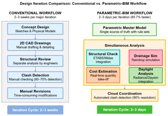
Figure 14.
Design Iteration Comparison: Conventional vs. parametric workflow.
The integrated parametric-BIM workflow fundamentally transformed the project delivery process. The hybrid Rhino–Grasshopper–Revit environment (Objective 1) successfully processed muti-concurrent discipline models, handling over 2.3 million geometric entities and 890,000 parametric relationships without significant performance degradation. This enabled parallel processing of performance analyses (structural, daylight, drainage, cost) that traditionally occurred sequentially, dramatically accelerating design exploration.
The developed parametric rule set (Objective 2), comprising 124 Geometric, 67 Material, and 89 Construction Rules, was instrumental. It empowered architects to manipulate design parameters directly while enforcing constructability constraints, preventing an estimated 94% of potential geometric violations that would have required rework. The rule set’s application, particularly the curvature-adaptive panel subdivision algorithm, successfully generated explicit boundaries and unique IDs for all 440,000+ stone panels, directly addressing the boundary ambiguity challenge.
The life-cycle digital twin (Objective 3) demonstrated its value beyond construction. The cloud-based model seamlessly transitioned into operations, with post-occupancy IoT integration enabling predictive maintenance, which reduced unplanned downtime compared to similar facilities. This validates the workflow’s role in bridging the constructability translation gap and maintaining parametric intelligence.
Quantitative validation (Objective 4) confirmed the methodology’s efficacy. The KPIs in Table 4 not only met but exceeded the targets set in the research objectives (≥90% clash resolution, <2% quantity variation, 35.4% schedule compression, >20 M RMB savings). The 91.2% clash resolution rate and 20.3 million RMB in cost savings provide robust empirical evidence of the workflow’s impact.
5.1.3. Economic Impact Assessment
The total cost savings of 20.3 million RMB (approximately 10.8% of the baseline estimate) can be attributed to several factors driven by the parametric-BIM workflow, as detailed in Table 5.
Major contributors include:
Material Optimization: The curvature-aligned panel subdivision (Section 4.3.5) saved 340 m3 of stone (≈1.2 million RMB).
Rework Reduction: Proactive clash resolution and rule-based geometric validation virtually eliminated design-induced field conflicts, saving 8.5 million RMB allocated for rework.
Schedule Compression: The 17-month reduction led to 10.6 million RMB in saved time-related overheads (financing, site management).
Labor Efficiency: Automated quantity take-off and robotic total station coordinates reduced field measurement time by 60%.
5.2. Discussion
5.2.1. Resolving the Three Bottlenecks
The results confirm that the rule-based digital twin methodology effectively addresses the three core bottlenecks. First, geometric interlacing was resolved through automated parametric rules, which processed 98% of surface intersections into watertight solids, eliminating manual stitching errors. Second, ambiguous boundaries on Mayan-irregular façades were transformed into explicit definitions via curvature-adaptive subdivision, enabling the precise mass customization of 440,000 stone panels. Third, the constructability translation gap was bridged by directly outputting CNC-ready fabrication data and robotic layout coordinates, creating a seamless digital thread from design to production and installation.
5.2.2. Workflow Synergy and Validation
The methodology’s efficacy stems from the integrated operation of its components. The five-layer architecture maintained data integrity, while the custom Grasshopper library (47 components) made advanced parametric operations executable. The four-phase implementation framework structured the application of rules to complex geometry, and the cloud-based Coordination Layer was instrumental in achieving the 91.2% clash resolution rate through real-time multi-disciplinary collaboration. The DSR approach was validated through a three-cycle evaluation (design, construction, operation), providing empirical evidence that the artifact is both effective in solving the targeted problems and robust in a real-world mega-project context.
5.2.3. Practical Implications and Challenges
The study underscores that the significant performance gains—including 20.3 million RMB cost savings and 35.4% schedule compression—are accompanied by notable implementation challenges. These include a 6-month learning curve for the custom tools, substantial hardware requirements (high-performance workstations), and the need for strict data governance to manage concurrent discipline models. These factors indicate that realizing the full benefits of such an advanced workflow requires commensurate investment in team upskilling, technological infrastructure, and process redesign.
6. Conclusions
This study establishes that a rule-based digital twin methodology, developed through a Design Science Research paradigm, effectively resolves three systemic bottlenecks in the delivery of free-form building envelopes: geometric interlacing complexity, ambiguous façade boundaries, and the constructability translation gap.
This research contributes to the fields of BIM and digital construction through three key advances. First, it operationalizes a life-cycle digital twin that transitions BIM from a static repository into a living, rule-driven model capable of preserving parametric intelligence and design intent as executable constraints beyond construction. Second, it proposes a structured five-layer integration framework (geometric, parametric, BIM, coordination, fabrication), offering a replicable architectural template for managing complexity in non-standard projects. Third, it extends DSR to architectural informatics, framing the digital twin as a socio-technical artifact that bridges the persistent gap between sculptural design intent and industrialized production logic.
Empirically validated through the Shenzhen Bay Culture Plaza project, the methodology delivered significant performance gains: 91.2% clash resolution prior to construction, 20.3 million RMB in cost savings (10.8% reduction), and 35.4% schedule compression, alongside the successful definition of over 440,000 unique façade panels. These outcomes demonstrate a viable, high-performance workflow for large-scale projects with extreme geometric complexity, providing a replicable model for industry adoption.
The study is based on a single revelatory case, which may affect the generalizability of findings to smaller or materially different projects. Additionally, the workflow demands notable upfront investment in tool customization, computational resources, and team training, which could impede immediate widespread adoption. Future research should therefore: (1) pursue multi-case validation across varied project contexts to assess scalability; (2) integrate machine learning for adaptive rule generation, potentially coupled with advanced manufacturing techniques for structural optimization [47]; and (3) develop supporting contractual and procedural frameworks to facilitate the mainstream implementation of digital twin-enabled project delivery.
Author Contributions
Conceptualization, X.L. (Xiang Li); Methodology, X.L. (Xiang Li); Software, W.G., X.L. (Xiaopei Liu) and J.Y.; Validation, W.G. and X.L. (Xiaopei Liu); Formal analysis, X.L. (Xiang Li); Investigation, W.G. and J.Y.; Resources, X.L. (Xiang Li); Data curation, X.L. (Xiang Li), W.G. and J.Y.; Writing—original draft, X.L. (Xiang Li) and X.L. (Xiaopei Liu); Writing—review and editing, X.L. (Xiang Li) and W.G.; Visualization, W.G., X.L. (Xiaopei Liu) and J.Y.; Supervision, X.L. (Xiang Li); Project administration, X.L. (Xiang Li); Funding acquisition, X.L. (Xiang Li). All authors have read and agreed to the published version of the manuscript.
Funding
This research was funded by National Natural Science Foundation of China, grant number 52308082; International Science and Technology Cooperation Project of the Ministry of Housing and Urban-Rural Development of China, grant number H20220017.
Data Availability Statement
The raw data supporting the conclusions of this article will be made available by the authors on request.
Conflicts of Interest
Authors Xiaopei Liu and Jun Yang were employed by the company Zhujia Smart City Construction Co., Ltd. The remaining authors declare that the research was conducted in the absence of any commercial or financial relationships that could be construed as a potential conflict of interest.
References
- Gilbert, B.P.; Dias-Da-Costa, D.; Lebée, A.; Foret, G. Veneer-based timber circular hollow section beams: Behaviour, modelling and design. Constr. Build. Mater. 2020, 258, 120380. [Google Scholar] [CrossRef]
- Li, T.; Ye, J.; Shepherd, P.; Wu, H.; Gao, B. Computational Grid Generation for the Design of Free-Form Shells with Complex Boundary Conditions. J. Comput. Civ. Eng. 2019, 33, 04019004. [Google Scholar] [CrossRef]
- Park, J. BIM-Based Parametric Design Methodology for Modernized Korean Traditional Buildings. J. Asian Arch. Build. Eng. 2011, 10, 327–334. [Google Scholar] [CrossRef]
- Su, M.; Yang, B.; Wang, X. Research on Integrated Design of Modular Steel Structure Container Buildings Based on BIM. Adv. Civ. Eng. 2022, 2022, 4574676. [Google Scholar] [CrossRef]
- Wang, P.; Wang, X.; Chen, W.; Li, Y.; Wang, J. Research on Integrated Design of Prefabricated Steel Frame Structures Based on BIM Technology with a Focus on Structural Safety. Buildings 2024, 14, 2341. [Google Scholar] [CrossRef]
- Ansah, M.K.; Chen, X.; Yang, H.; Lu, L.; Lam, P.T. Developing an automated BIM-based life cycle assessment approach for modularly designed high-rise buildings. Environ. Impact Assess. Rev. 2021, 90, 106618. [Google Scholar] [CrossRef]
- Růžička, J.; Veselka, J.; Rudovský, Z.; Vitásek, S.; Hájek, P. BIM and Automation in Complex Building Assessment. Sustainability 2022, 14, 2237. [Google Scholar] [CrossRef]
- Puppa, G.D.; Trautz, M. Multi-objective shape optimization of shell structures based on buckling forms. In Proceedings of the International Association for Shell and Spatial Structures (IASS), Amsterdam, The Netherlands, 17–20 August 2015. [Google Scholar]
- Xiao, J.C.; Chen, J.; Li, Q.; Xia, S.Q. Shape and Cross-Section Optimization of Spatial Grid Structures Using Genetic Algorithm. Adv. Mater. Res. 2012, 479–481, 1463–1467. [Google Scholar] [CrossRef]
- Kociecki, M.; Adeli, H. Shape optimization of free-form steel space-frame roof structures with complex geometries using evolutionary computing. Eng. Appl. Artif. Intell. 2015, 38, 168–182. [Google Scholar] [CrossRef]
- Goldbach, A.-K.; Lázaro, C. CAD-integrated parametric design and analysis of lightweight shell structures. Structures 2024, 64, 106566. [Google Scholar] [CrossRef]
- Lastra, A. Architectural Form-Finding Through Parametric Geometry. Nexus Netw. J. 2022, 24, 271–277. [Google Scholar] [CrossRef]
- Pugnale, A. Integrating Form, Structure and Acoustics: A Computational Reinterpretation of Frei Otto’s Design Method and Vision. J. Int. Assoc. Shell Spat. Struct. 2018, 59, 75–86. [Google Scholar] [CrossRef]
- Nagata, K.; Honma, T. Form for free surface shell structure using swarm intelligence with manipulation for decent solution search. J. Struct. Constr. Eng. Transactions AIJ 2013, 78, 345–354. [Google Scholar] [CrossRef]
- Wang, X.; Zhu, S.; Zeng, Q.; Guo, X. Improved multi-objective Hybrid Genetic Algorithm for Shape and Size Optimization of Free-form latticed structures. J. Build. Eng. 2021, 43, 102902. [Google Scholar] [CrossRef]
- Zhao, Z.; Wu, J.; Qin, Y.; Liang, B. The strong coupled form-finding and optimization algorithm for optimization of reticulated structures. Adv. Eng. Softw. 2020, 140, 102765. [Google Scholar] [CrossRef]
- Liao, F.; Pan, H.; Zhang, J. Design and research of prefabricated building construction collaborative management system based on BIM technology. In Advances in Frontier Research on Engineering Structures; CRC Press: Boca Raton, FL, USA, 2022; Volume 1, pp. 413–417. [Google Scholar]
- Manzoor, B.; Othman, I.; Kang, J.M.; Geem, Z.W. Influence of Building Information Modeling (BIM) Implementation in High-Rise Buildings towards Sustainability. Appl. Sci. 2021, 11, 7626. [Google Scholar] [CrossRef]
- Liapi, K.A.; Papantoniou, A.; Nousias, C. Square tessellation patterns on curved surfaces. In Search of a Parametric Design Method; eCAADe: Brussels, Belgium, 2017; pp. 371–378. [Google Scholar]
- Stitic, A.; Nguyen, A.C.; Rad, A.R.; Weinand, Y. Numerical Simulation of the Semi-Rigid Behaviour of Integrally Attached Timber Folded Surface Structures. Buildings 2019, 9, 55. [Google Scholar] [CrossRef]
- Colace, F.; Guida, C.G.; Gupta, B.; Lorusso, A.; Marongiu, F.; Santaniello, D. A BIM-Based Approach for Decision Support System in Smart Buildings. In Proceedings of the Seventh International Congress on Information and Communication Technology, ICICT 2022, London, UK, 4–6 March 2022; Volume 1, pp. 471–481. [Google Scholar]
- Rehman, S.U.; Kim, I.; Choi, J. Data-driven integration framework for four-dimensional building information modeling simulation in modular construction: A case study approach. J. Comput. Des. Eng. 2023, 10, 2288–2311. [Google Scholar] [CrossRef]
- Liu, X.; He, C.; Zhao, H.; Jia, J.; Liu, C. Building information modeling indoor path planning: A lightweight approach for complex BIM building. Comput. Animat. Virtual Worlds 2021, 32, e2014. [Google Scholar] [CrossRef]
- Sun, W.; Zhao, L. BIM-Based Building Performance Simulation Analysis: A Multi-Parameter-Driven Approach to Building Energy Efficiency and Carbon Reduction. Int. J. Pattern Recognit. Artif. Intell. 2023, 37, 2354019. [Google Scholar] [CrossRef]
- Jung, C.; Awad, R.; Awad, J. A study of optimal design process for complex-shaped skyscrapers’ structural systems in United Arab Emirates. Ain Shams Eng. J. 2022, 13, 101683. [Google Scholar] [CrossRef]
- Wang, X.; Chen, Y.; Wang, Z.; Tang, Y.; Wang, X.; Lu, C. Multi-Scale Modeling and Optimization of Single-Layer Reticulated Shell Structures Using Multi-Point Constraint and Variable Density Methods. Buildings 2025, 15, 174. [Google Scholar] [CrossRef]
- Chen, G.; Zhang, H.; Rasmussen, K.J.; Fan, F. Modeling geometric imperfections for reticulated shell structures using random field theory. Eng. Struct. 2016, 126, 481–489. [Google Scholar] [CrossRef]
- Hevner, A.R.; March, S.T.; Park, J.; Ram, S. Design science in Information Systems research. MIS Q. Manag. Inf. Syst. 2004, 28, 75–105. [Google Scholar] [CrossRef]
- March, S.T.; Storey, V.C. Design Science in the Information Systems Discipline: An Introduction to the Special Issue on Design Science Research. MIS Q. 2008, 32, 725–730. [Google Scholar] [CrossRef]
- Lai, X.; He, Z. Generalized parametric structural design: Framework and perspectives. In Advances in Engineering Materials, Structures and Systems: Innovations, Mechanics and Applications; Zingoni, A., Ed.; CRC Press: Boca Raton, FL, USA, 2019; pp. 2328–2333. [Google Scholar]
- Turrin, M.; von Buelow, P.; Stouffs, R. Design explorations of performance driven geometry in architectural design using parametric modeling and genetic algorithms. Adv. Eng. Informatics 2011, 25, 656–675. [Google Scholar] [CrossRef]
- Patel, V.; Acharya, A.; Waggoner, M. Roof Design and Construction of the Narendra Modi Stadium—The World’s Largest Cricket Stadium. Struct. Eng. Int. 2023, 33, 265–269. [Google Scholar] [CrossRef]
- Zhang, S.; Feng, C.; Fan, Y.; Xia, Y. Jingang Cultural Center: Complex-Shaped Fair-Faced Concrete Structure. Struct. Eng. Int. 2023, 33, 425–430. [Google Scholar] [CrossRef]
- Getuli, V.; Bruttini, A.; Rahimian, F. Parametric design methodology for developing BIM object libraries in construction site modeling. Autom. Constr. 2025, 170, 105897. [Google Scholar] [CrossRef]
- Girardet, A.; Boton, C. A parametric BIM approach to foster bridge project design and analysis. Autom. Constr. 2021, 126, 103679. [Google Scholar] [CrossRef]
- Peng, J.; Yang, Y.; Fu, X.; Hou, Y.; Ding, Y. Grasshopper platform-assisted design optimization of fujian rural earthen buildings considering low-carbon emissions reduction. Sci. Rep. 2024, 14, 18229. [Google Scholar] [CrossRef]
- Zhang, W.; Liu, Y.; Yu, S.; Zhang, Y.; Yang, L.; Qi, L. The Application Research of BIM Technology in the Construction Process of Yancheng Nanyang Airport. Buildings 2023, 13, 2846. [Google Scholar] [CrossRef]
- Bai, J.; Zhang, J.; Jin, S.; Du, K.; Wang, Y.-H. A multi-modal-analysis-based simplified seismic design method for high-rise frame-steel plate shear wall dual structures. J. Constr. Steel Res. 2021, 177, 106484. [Google Scholar] [CrossRef]
- Orzhekhovskiy, A.; Priadko, I.; Tanasoglo, A.; Fomenko, S. Design of stadium roofs with a given level of reliability. Eng. Struct. 2020, 209, 110245. [Google Scholar] [CrossRef]
- Tian, L.; Hao, J.; Wei, J.; Zheng, J. Integral lifting simulation of long-span spatial steel structures during construction. Autom. Constr. 2016, 70, 156–166. [Google Scholar] [CrossRef]
- Mai, G.; Kuang, W.; Zhu, D.; Song, Y.; Zou, X.; Qiu, Y.; Xiong, Z. Stability and Construction Control of Existing Steel Truss Roof Reconstruction Projects: Case Analysis and Numerical Simulation. Buildings 2025, 15, 2059. [Google Scholar] [CrossRef]
- Jones, N.L.; Greenberg, D.P.; Pratt, K.B. Fast computer graphics techniques for calculating direct solar radiation on complex building surfaces. J. Build. Perform. Simul. 2012, 5, 300–312. [Google Scholar] [CrossRef]
- Russo, M.; Russo, V. Geometric analysis of a space grid structure by an integrated 3D survey approach. Int. Arch. Photogramm. Remote Sens. Spat. Inf. Sci. 2022, 46, 465–472. [Google Scholar] [CrossRef]
- Veenendaal, D.; Bakker, J.; Block, P. Structural Design of the Flexibly Formed, Mesh-Reinforced Concrete Sandwich Shell Roof of NEST HiLo. J. Int. Assoc. Shell Spat. Struct. 2017, 58, 23–38. [Google Scholar] [CrossRef]
- Chai, W.; Zhang, C.; Wang, Z. Analysis on the Application of BIM Technology in the Interior Decoration Design of Public Buildings. In Proceedings of the 2022 International Conference on Big Data, Information and Computer Network (BDICN), Sanya, China, 20–22 January 2022; pp. 428–431. [Google Scholar]
- Károlyfi, K.A.; Szép, J. A Parametric BIM Framework to Conceptual Structural Design for Assessing the Embodied Environmental Impact. Sustainability 2023, 15, 11990. [Google Scholar] [CrossRef]
- Chen, M.-T.; Zuo, W.; Chen, Y.; Zhao, O.; Cheng, B.; Zhao, J. Parametric topology optimization design and analysis of additively manufactured joints in spatial grid structures. Eng. Struct. 2023, 300, 117123. [Google Scholar] [CrossRef]


Disclaimer/Publisher’s Note: The statements, opinions and data contained in all publications are solely those of the individual author(s) and contributor(s) and not of MDPI and/or the editor(s). MDPI and/or the editor(s) disclaim responsibility for any injury to people or property resulting from any ideas, methods, instructions or products referred to in the content. |
© 2026 by the authors. Licensee MDPI, Basel, Switzerland. This article is an open access article distributed under the terms and conditions of the Creative Commons Attribution (CC BY) license.