Abstract
To investigate the cyclic behavior of FRP-reinforced steel fiber reinforced concrete (SFRC) composite walls, this paper proposes a section-based finite spring calculation method (FSCM) to reliably predict the cyclic response of such walls under seismic loads. The proposed model accounts for the bond-slip effect of FRP bars and the confining action of transverse reinforcement in the boundary elements. Numerical calculations were conducted on six composite wall specimens with varying longitudinal bar types, fiber volume fractions, concrete strengths, and axial compression ratios. The results indicate that the established calculation method efficiently characterizes the “pinching” effect induced by the linear-elastic properties of FRP bars, and the obtained hysteretic curves are in good agreement with experimental data. Furthermore, the model accurately predicts the load-bearing capacity and residual displacements of the FRP-reinforced SFRC composite walls. Specifically, the average error of peak load calculation for all specimens ranges from −3.36% to 7.36%, and the predicted residual displacements correlate well with the experimental data. These findings demonstrate the applicability of the proposed model for key seismic performance indicators and provide a reliable basis for the research and engineering application of FRP-reinforced SFRC composite walls.
1. Introduction
Shear walls are core lateral force-resisting components in high-rise building structures, playing a pivotal role in maintaining structural stability under seismic action [1]. China is located in a high-seismic-intensity zone, with frequent occurrences of strong earthquakes that cause severe damage to structural systems [2]. Traditional reinforced concrete (RC) structures inherently exhibit prominent weaknesses such as brittle shear failure and insufficient shear capacity under seismic loading, which not only restrict their seismic performance, but also lead to excessive residual deformation and serious concrete damage after earthquakes [3,4]. These post-earthquake drawbacks often result in functional failure and difficulties in repairs, bringing enormous financial losses and hindering the post-seismic rehabilitation process [5,6]. With the development of earthquake engineering, the concept of “earthquake-resilient structures” has been widely concerned, which requires structures to quickly restore their functions through simple repair or even without repair after earthquakes [7].
To achieve the goal of structural resilience, scholars have explored the application of high-performance materials in RC structures, aiming to address the aforementioned weaknesses of RC members. Among these materials, FRP stands out as an effective and applicable strengthening method for improving the seismic performance of RC members with insufficient shear capacity, enabling damage mitigation and sustainable enhancement of structural safety [8,9]. Specifically, carbon fiber reinforced polymer (CFRP) bars, with their advantages of high tensile strength, light weight, and corrosion resistance [10,11], have become an ideal alternative to traditional steel bars in seismic resilient structures. Relevant studies have shown that FRP-reinforced concrete structures are able to efficiently mitigate residual displacement and improve self-centering performance [12]. Li et al. [13] conducted quasi-static tests on four specimens to investigate the effect of replacing reinforcement with CFRP bars in hidden columns on the seismic performance of concrete frame structures. The results showed that CFRP bars enhanced the load-bearing capacity of the specimens, improved the peak displacement, and significantly reduced residual deformation; the CSRC frames retained the failure mode of strong columns and weak beams characteristic of traditional RC frames. Zhang et al. [14] conducted low-cyclic reversed cyclic loading tests on concrete square columns with all longitudinal reinforcements replaced by CFRP bars. The results revealed that using CFRP bars as longitudinal reinforcements significantly reduced the residual displacement and residual crack width of the specimens and enhanced their self-centering capability after earthquakes.
However, owing to the low elastic modulus and poor bond performance of CFRP bars, concrete structures strengthened with CFRP bars are frequently confronted with related problems such as insufficient ductility, and poor energy dissipation capacity, which limit their further engineering application [15,16]. Zhao et al. [17] conducted low-cyclic reciprocating loading tests on RC shear walls with CFRP bars. The results indicated that the ductility and energy dissipation capacity of the specimens with CFRP bars were significantly reduced compared with those of conventional reinforced concrete (RC) shear walls.
Steel fiber reinforced concrete (SFRC), as a high-performance composite material, has been proven to effectively make up for the defects of ordinary concrete [18,19]. The random distribution of steel fibers in the concrete matrix can restrain crack propagation, improve the toughness and deformation capacity, and enhance the ductility and energy dissipation performance of structural components [20,21]. Previous experimental studies have confirmed that the combination of FRP bars and SFRC can synergistically improve the seismic performance of concrete structures: SFRC can compensate for the insufficient ductility and energy dissipation of FRP-reinforced structures, while FRP bars can provide excellent self-centering performance for SFRC structures [22,23]. This composite form has broad application prospects in earthquake-resilient structures, attracting extensive attention from researchers [24].
The finite element analysis has emerged as a vital method for investigating the seismic behavior of structural components. Some scholars have established finite element models of FRP-reinforced concrete structures using commercial software such as Abaqus (version 6.9) [25] and Opensees (version 3.3.0) [26]. Zhang et al. [27] conducted test-validated OpenSEES numerical studies on UHPC frames and clarified the seismic performance enhancement effect of FRP bars (SFCBs, BFRP bars): compared with steel bars, FRP bars significantly improved the peak load and displacement of UHPC frames, and SFCB-type FRP bars further optimized the frame’s performance degradation and post-earthquake recoverability. Mansouri et al. [28] validated the effectiveness of Abaqus numerical simulations using experimental results, then conducted parametric analyses on FRP-strengthened CFDSP shear walls (investigating FRP type, layers, fiber orientation, wrap configuration and concrete compressive strength), finding CFRP/GFRP increased lateral capacity by 49.66%/21.80%.
Unlike traditional steel bars with ribbed surfaces that form mechanical interlocking with concrete, FRP bars typically have smooth surfaces or weak interfacial adhesion, resulting in inherently low bond strength [29,30]. This significant bond-slip behavior directly disrupts the effective stress transfer mechanism between CFRP bars and concrete: it causes uneven stress distribution along the CFRP bar length, delays the initiation of concrete cracks but accelerates their propagation, and ultimately leads to deviations in predicting key seismic indicators such as bearing capacity, stiffness degradation, and residual deformation.
Therefore, the bond-slip effect between FRP bars and surrounding concrete is of vital importance to the numerical simulation of FRP bar-reinforced structures, as its reasonable consideration is a key prerequisite for ensuring the accuracy and reliability of seismic performance simulation results of such structures. Zhou et al. [31] confirmed the indispensability of considering the FRP bar bond-slip effect via 3D nonlinear finite element sensitivity analysis on FRP-retrofitted RC beams, revealing that different bond-slip laws markedly affect seismic simulation accuracy, and neglecting this effect will cause obvious deviations in predicting structural failure modes and seismic response. Guo et al. [32] further validated this conclusion in FRP-confined RC column simulations, emphasizing that the FRP bar bond-slip effect is a key factor for reliable numerical modeling. Their results showed that ignoring this effect leads to significant underestimation of the reduction in member stiffness and energy dissipation capacity, as well as inaccurate predictions of column top displacement and ductility.
Although experimental studies have confirmed the superior seismic performance of CFRP-reinforced SFRC structures, the lack of accurate numerical calculation models that systematically consider the bond-slip effect and integrate key factors such as transverse reinforcement confinement has become a major obstacle. Without accounting for bond-slip, existing models overestimate the collaborative work efficiency between CFRP bars and SFRC, leading to inaccurate predictions of structural damage modes and seismic response laws. This not only restricts the in-depth understanding of the seismic mechanism of such composite structures but also hinders their reliable engineering application. Therefore, it is urgent to develop a comprehensive and accurate numerical calculation method to predict the cyclic response of CFRP-reinforced SFRC composite walls under seismic loads.
Based on the above research background and existing gaps, this study aims to propose an accurate numerical calculation method for predicting the seismic performance of CFRP-reinforced SFRC composite walls. The main research contents are as follows: (1) Discretize the shear wall into elastic zones and plastic hinge zones, and establish a discrete analysis model of shear walls using the finite spring method; (2) Develop a numerical calculation process capable of characterizing the seismic response of composite walls, thereby realizing effective prediction of the cyclic load response of composite walls; (3) Select six composite wall specimens with different longitudinal reinforcement types, concrete strengths, and axial compression ratios for numerical calculation, analyze key seismic performance indicators such as hysteretic curves, bearing capacity, and residual displacement, and validate the accuracy and reliability of the established numerical calculation method by comparing with experimental data.
The innovations of this study are mainly reflected in: (1) targeting the key bottleneck of existing research, a numerical calculation method comprehensively considering the bond-slip effect and the confinement effect of transverse reinforcement is proposed, avoiding the insufficient accuracy of traditional models caused by ignoring interface behavior and boundary constraints; (2) a concise and efficient numerical calculation process is established, which can accurately predict the seismic performance of composite walls without complex refined modeling, improving the engineering practicality of the method.
The expected research results will have important academic and engineering significance: (1) at the academic level, it enriches the numerical calculation theory system of CFRP-reinforced SFRC composite structures and deepens the understanding of the seismic mechanism of composite walls under the influence of the bond-slip effect and transverse reinforcement confinement; (2) at the engineering level, it provides a convenient and reliable numerical calculation tool for the seismic design, performance evaluation, and optimization of CFRP-reinforced SFRC composite walls, reduces the threshold of engineering application, and promotes the wide application of such high-performance composite structures in seismic resilient buildings.
2. Experimental Overview
Low-cycle repeated loading tests were carried out on six specimens, with the original experimental details reported in Ref. [33]. The specimen variables including longitudinal reinforcement type, VF, concrete strength, and axial compression ratio, and the detailed design parameters are presented in Table 1. The specimen naming follows a clear convention: “RC” denotes ordinary reinforced concrete shear walls with traditional steel bar reinforcement; “C” is prefixed to indicate longitudinal reinforcement using CFRP bars; “SF” signifies the adoption of SFRC; the numerals “0.75” and “1.5” following “SF” represent the VF (in %); “CF50” indicates the concrete strength grade is CF50; and “0.33” represents an axial compression ratio of 0.33. Figure 1a displays the specimen details. The quasi-static experimental setup is illustrated in Figure 1b. And the drift-controlled loading procedure is illustrated in Figure 1c, where the net clear height of 2560 mm of the specimens was adopted for the drift ratio calculation. The mechanical properties of materials are shown in Table 1 and Table 2. The experimental results are reported in Ref. [33] and are used for the validation of the proposed numerical model.

Table 1.
Design parameters of specimens.
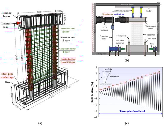
Figure 1.
Experimental overview: (a) Dimension and reinforcement configurations; (b) Loading schematic diagram; (c) Loading procedure.
Table 2.
Mechanical properties of reinforcements.
3. Establishment of FSCM
The bond strength between concrete and CFRP bars is relatively low, and the resulting significant slip cannot be neglected [34,35]. For a more reasonable and accurate prediction of the cyclic behavior of FRP-reinforced SFRC composite walls under quasi-static loading, this study proposes the Finite Spring Calculation Method (FSCM) based on a finite spring-based design philosophy [36], whose main innovation lies in integrating the bond-slip effect of FRP bars and the confinement effect of transverse reinforcement in boundary elements, thereby overcoming the limitations of generic models in simulating such composite structures.
3.1. Basic Assumptions
In the proposed calculation method, the following basic assumptions are adopted for analysis:
- (1)
- The rotation induced by bending deformation is concentrated in the plastic hinge region, with the cross-section curvature distributed uniformly therein. This assumption is derived from the mechanical behavior of flexural members: under cyclic bending, the inelastic deformation of FRP-reinforced SFRC composite walls is predominantly concentrated in the plastic hinge zone (the region with maximum curvature), while the elastic zones outside the hinge undergo negligible inelastic deformation. Uniform curvature distribution within the plastic hinge zone is a standard simplification in discrete numerical methods, as it balances computational efficiency and the characterization of key deformation mechanisms without introducing excessive complexity.
- (2)
- The plane section assumption is satisfied for the concrete cross-section. As a foundational premise in beam-column and shear wall flexural analysis, this assumption is valid for members with uniform cross-sectional geometry and reinforcement layout. It ensures the strain compatibility between concrete, FRP bars, and steel reinforcement, which is essential for accurately calculating the stress distribution across the section based on material constitutive models.
- (3)
- The strain and stress of CFRP bars displayed even distribution in the plastic hinge area. This assumption is based on two core mechanical characteristics: first, CFRP bars exhibit linear-elastic behavior without yielding or plastic deformation, meaning their stress–strain relationship remains linear under cyclic loading; second, the uniform curvature distribution assumed in assumption (1) leads to linear strain distribution along the cross-section, and the consistent bond behavior ensures that CFRP bars do not experience significant stress gradients within the plastic hinge zone. This simplification is necessary to streamline the stress calculation of FRP bars in the discrete spring framework.
- (4)
- The tensile behavior of concrete was not considered (including the direct tensile contribution of steel fibers and their crack-bridging effect). This simplification is justified by the mechanical properties of concrete and the composite system’s load-bearing mechanism: the tensile strength of concrete is relatively low compared to its compressive strength, and its contribution to the composite wall’s tensile capacity is negligible compared to FRP bars. Additionally, the crack restraint effect of steel fibers in SFRC primarily improves ductility and crack width control rather than enhancing tensile strength to a level that impacts the overall stress balance. Ignoring concrete’s tensile strength simplifies the section force equilibrium calculation without distorting the core load-bearing mechanism of the FRP-reinforced SFRC system.
3.2. Analysis Model and Calculation Procedures
On the basis of these assumptions, the wall specimens are separated into three regions: the base and top elastic regions and the plastic hinge region, as illustrated in Figure 2. It was assumed that the CFRP bars were connected to the concrete via multiple bond-slip spring elements. The elastic regions at the top and base were further discretized into n and m segments, respectively, with each segment serving as a bond-slip spring element of length l. SB and SC denote the slip values of the CFRP bars on the top side and the base side of the elastic region, respectively, while σB and σC represent the corresponding stresses. σH refers to the stress in the CFRP bars within the plastic hinge zone.
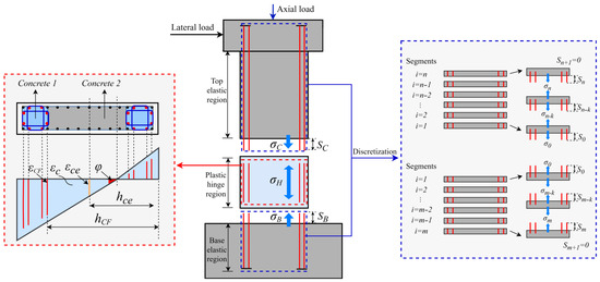
Figure 2.
Analytical model of the wall specimen.
The FSCM is a simplified mechanical calculation method rather than commercial finite element software. It is independently developed and implemented with C++ to conduct core calculations, including bond-slip spring force balance, section stress–strain iteration, and extraction of global mechanical responses (hysteretic curves, peak load, residual displacement, etc.). The calculation flowchart of the FSCM is shown in Figure 3, and the details of each step are as follows:
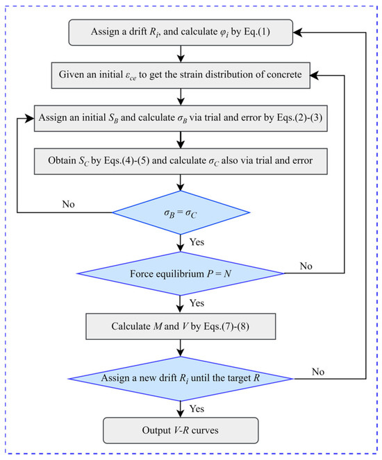
Figure 3.
Calculation flowchart of the FSCM.
- (1)
- For a specified drift Ri, the curvature φi of the cross-section within the plastic hinge zone is calculated as shown in Equation (1).where α and Lp are the bending deformation ratio and the plastic hinge length of the specimen, obtained based on the data measured by vertical displacement gauges and the calculation method described in Ref. [16].
- (2)
- Given an initial strain value εce of the neutral axis of the concrete section, the strain distributions of concrete in the plastic hinge zone section can be derived based on Assumption 2.
- (3)
- The slip SB of the CFRP bars at the top end of the base elastic region is assigned to S0, which is the slip of the first spring element after segmentation.
- (4)
- Given the initial stress of the CFRP bar in the first spring element as σ0, then the stress σk and slip Sk of the CFRP bars in the (k + 1)th spring element can be obtained from Equations (2) and (3).where As and ds represent the cross-sectional area and diameter of CFRP bars; τ(S) is the bond stress-slip function of the CFRP bars [37]; fCF−1(σ) is the inverse function of the stress–strain relationship of the CFRP bars.
- (5)
- Repeat the above steps until the calculation proceeds to the last spring element m at the end of the reinforcement, which should satisfy the boundary condition that both the stress and slip at the end are zero. If the calculation result satisfies Sm+1 = 0, the assumed initial stress σ0 is the actual stress σB on the base side of the CFRP bars. If the condition is not satisfied, return to Step (4) and repeat the process.
- (6)
- Based on the conditions that σH = σB and Assumption 3, the strain of CFRP bars in the plastic hinge zone σCF and the slip SC of the top spring zone can be calculated, as shown in Equations (4) and (5), respectively.
- (7)
- The stress σC in the top spring zone can also be obtained through the above steps. If the condition σC = σB is satisfied, then the εCF is the actual strain of the CFRP bars within the plastic hinge zone. If the condition is not satisfied, return to Step (3) and repeat the process.
- (8)
- Repeat the above steps for all CFRP bars, and the actual strain distribution of the CFRP bars considering the influence of the bond-slip effect within the plastic hinge zone can be derived.
- (9)
- On the basis of the given material constitutive models, the concrete stress fc, steel bar stress fs and CFRP bar stress fCF can be derived. And the resultant force P of the sectional stress can be further calculated, as shown in Equation (6).where Ac, As and ACF are the cross-sectional areas of the concrete fibers, steel bars and CFRP bars, respectively.
- (10)
- If the resultant force P is in equilibrium with the applied axial load N, the bending moment M of the concrete section and the horizontal force Vi corresponding to the drift ratio Ri can be calculated, as shown in Equations (7) and (8). If this equilibrium condition is not satisfied, the calculation shall be repeated from step (2).where hc, hs and hCF are the distances from the concrete fiber elements, steel bars and CFRP bars to the neutral axis, respectively.
- (11)
- Assign a new drift ratio Ri and repeat the above steps until the drift specified in the loading protocol is achieved.
4. Constitutive Model of Materials
4.1. Constitutive Model of Concrete
The concrete model [38] adopted in this study can account for the confinement effect provided by linear reinforcement (including traditional stirrups and steel tubes), as shown in Figure 4. Where fp′ is the cylinder compressive strength of unconfined concrete, with fp′ = 0.79fcu [39]; fc′ is the cylinder compressive strength of confined concrete, with fc′ = Kfp′, in which K is the strength enhancement coefficient [40] and is calculated by Equation (9); εp0 and εc0 are the peak strains of unconfined and confined concrete, respectively, and are calculated by Equation (10); Esec is the secant modulus at the peak stress point; D is the parameter controlling the slope of the curve’s descending branch, serving to account for the influence of the member section’s strain gradient under bending action on concrete’s stress–strain behavior and is calculated by Equation (11). The unloading and reloading criteria for the concrete are illustrated in Figure 4.
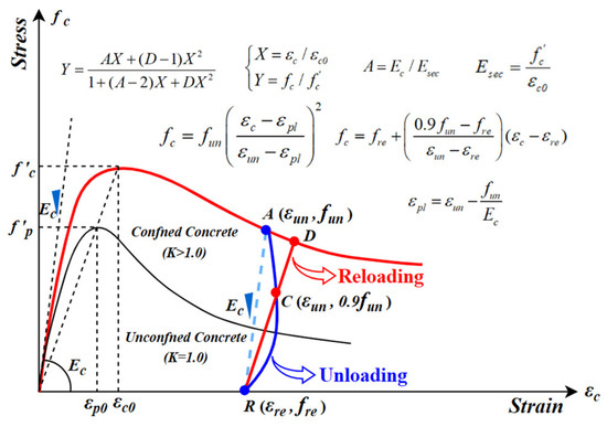
Figure 4.
Constitutive model and hysteretic rules of confined concrete.
4.2. Constitutive Model of Reinforcements
The stress–strain relationship and hysteretic rules of steel bars are depicted in Figure 5a, which was modified based on the M-P model [41] according to the test results. Figure 5b shows the constitutive model of CFRP bars.
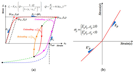
Figure 5.
Constitutive model of: (a) Steel bars; (b) CFRP bars.
4.3. Bond-Slip Model of CFRP Bars
To account for the bond degradation effect between FRP bars and concrete under cyclic loading, the bond-slip model [37] is modified, as shown in Figure 6. Among them, Path ① represents the skeleton curve of bond stress-slip under monotonic loading. When the bond stress reaches the maximum value under cyclic loading, the bond behavior will degrade, and the skeleton curve will follow Path ②. The maximum bond stress τmax and corresponding slip Sτmax are calculated using Equations (12) and (13) [42,43].
where c is the concrete cover thickness; db, lembed and n are the diameter, embedment length and number of FRP bars, respectively; s and Atr are the spacing and cross-sectional area of stirrups; η denotes the surface modification coefficient of reinforcements, specifically taken as 0.43 for CFRP in this study. This value is determined based on the smooth, non-ribbed surface characteristics of the CFRP bars adopted herein, and further calibrated against the bond test results reported by Ref. [43], and verified through systematic sensitivity analysis.
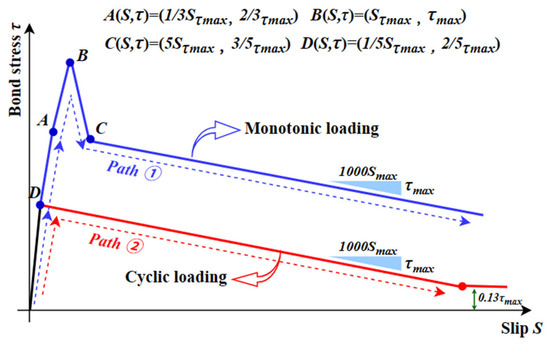
Figure 6.
Bond stress-slip relationship model.
Hysteretic rules for bond stress before and after reaching τmax are shown in Figure 7. The paths are explained in detail below:
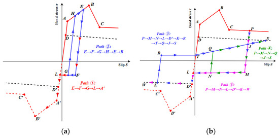
Figure 7.
Hysteretic rules for bond stress: (a) Before τmax; (b) After τmax.
- (1)
- Before bond stress reaches τmax (Figure 7a):
- Unload from point E along initial stiffness to point F (−0.13τmax), then move parallel to S-axis to the opposite skeleton curve (Path ①);
- Reload from point G during Path ①: Return to skeleton curve along initial stiffness (Path ②).
- (2)
- After bond stress reaches τmax (Figure 7b):
- Unload from point P along initial stiffness to point M (−ατmax), then move parallel to S-axis; reverse load follows cyclic skeleton curve (Path ③);
- Unload from point K during Path ③: Rise along the initial stiffness to point R, then move horizontally to point T, and finally follow the straight line TQ back to the cyclic skeleton curve (Path ④). Bond stress at point J is calculated via Equation (14) using P (Sp, τp), the maximum slip point.
- Reload before reaching point L during the unloading process of Path ③: Extend along the initial stiffness to point Q on the line TS, then return to the cyclic skeleton curve via QS (Path ⑤).
where fcycle(SP) denotes the cyclic loading skeleton curve function, and β represents the bond stress degradation rate under cyclic loading. After a sensitivity analysis within a reasonable range (0.6, 0.8, 1.0) based on Ref. [37], the value of 0.8 was adopted in this model.
5. Calculation Results and Analysis
5.1. Hysteresis and Skeleton Curves
The calculation results are obtained using the aforementioned calculation method, as shown in Figure 8 and Figure 9. Meanwhile, the peak load values and errors are summarized in Table 3. It can be seen that the numerical calculation results show satisfactory overall correspondence with the test data, with basically consistent initial stiffness. The calculated hysteretic curves also exhibit the “pinching” characteristic of low residual deformation, which is induced by the linear elastic behavior of CFRP bars and the effect of bond-slip. The average error of the peak load for all specimens ranges from −3.36% to 7.36%, indicating high accuracy of the proposed model.
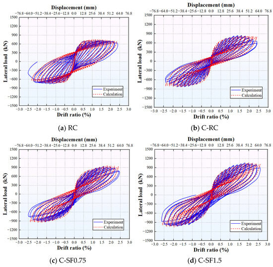
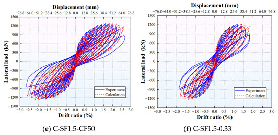
Figure 8.
Comparison of hysteresis curves.
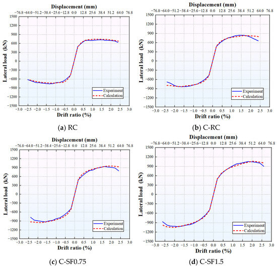
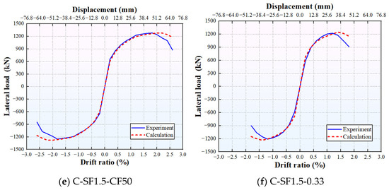
Figure 9.
Comparison of skeleton curves.
Table 3.
Comparison of calculation and experimental results of peak loads.
Specifically, a comparison of Figure 9b–d reveals that the calculated results follow the same variation trend as the experimental results: both the peak load and peak drift increase with the rise in VF. For example, compared with Specimen C-RC, the calculated peak loads of Specimens C-SF0.75 and C-SF1.5 increase by 19.70% and 30.28%, respectively, and the corresponding peak drift ratios increase by 12.5% and 25.0%, respectively. In addition to VF, both the peak load and peak drift ratio increase with the enhancement of concrete strength. For instance, the calculated peak load of Specimen C-SF1.5-CF50 is 18.53% higher than that of Specimen C-SF1.5, and the corresponding peak drift ratio increases by 10.0%. In contrast, the axial compression ratio shows an opposite effect on the peak drift while promoting the peak load. As an illustration, compared with Specimen C-SF1.5, the calculated peak load of Specimen C-SF1.5-0.33 increases by 26.49%, and the corresponding peak drift ratio decreases by 30.0%.
Collectively, the calculated results under the aforementioned parameter variations are consistent with the experimental results in terms of variation trends and exhibit a high coincidence degree.
5.2. Residual Deformation
The calculated and experimental residual displacements are illustrated in Figure 10, with corresponding values listed in Table 4. It is evident that the calculated results are in good overall consistency with the experimental data. First, Figure 10a,b reveal that the proposed numerical model is capable of capturing the effects of the linear elastic behavior of CFRP bars on the residual deformation of the specimens. For instance, at a drift of 1.8%, the calculated residual displacement of Specimen C-RC is reduced by 63.44% compared with that of Specimen RC, demonstrating a favorable self-centering capacity. Second, with the increase in the VF, the calculated residual displacement exhibits a slight upward trend, yet still maintains a superior self-centering performance relative to Specimen RC. As an illustration, at a drift of 1.8%, the calculated residual displacements of Specimens C-SF0.75 and C-SF1.5 are reduced by 58.06% and 61.29%, respectively, compared with that of Specimen RC. With the increase in the axial compression ratio, the calculated residual displacement of the specimens increases, which is consistent with the variation trend reflected by the experimental results. For example, at a drift of 1.8%, the calculated residual displacement of Specimen C-SF1.5-0.33 is 8.33% lower than that of Specimen C-SF1.5. In contrast, increasing the concrete strength exerts a negligible influence on the calculated residual displacement of the specimens.
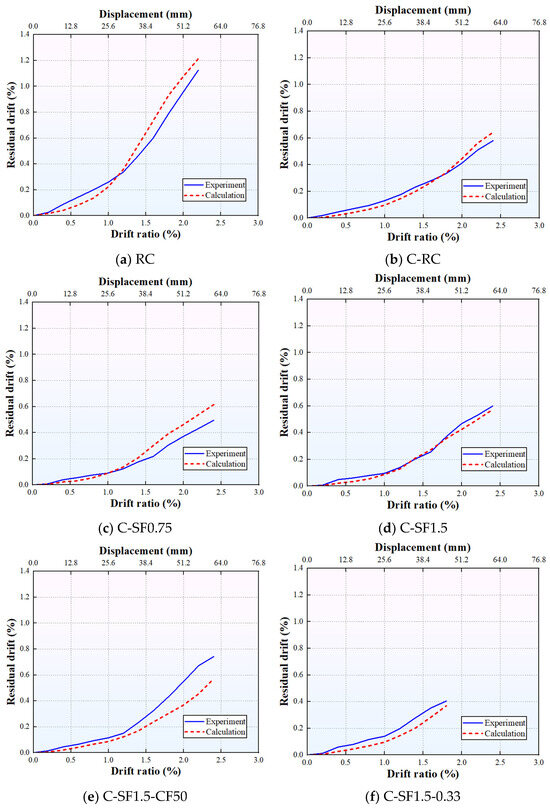
Figure 10.
Comparison of residual drifts.
Table 4.
Comparison of residual drift values.
5.3. Energy Dissipation
The energy dissipation was calculated by numerically integrating the enclosed area of the measured hysteretic curves for each loading cycle, with cumulative energy dissipation (CED) obtained by summing the energy dissipation of all cycles. The calculated and experimental CED of the specimens are illustrated in Figure 11, with corresponding values listed in Table 5. As can be seen, the simulation results for RC and C-RC specimens match well with the experimental results, with a maximum error controlled within 6%. This indicates that the proposed calculation method is capable of capturing the phenomenon of reduced energy dissipation. For instance, compared with the Specimen RC, the calculated CED of the Specimen C-RC decreases by 47.51%, which is consistent with the experimental findings. However, increasing the VF, the calculated CED is consistently lower than the experimental results, accompanied by a gradual increase in the error margin. This discrepancy arises because the calculation method neglects the tensile strength of concrete, thereby failing to account for the additional energy dissipation enhancement contributed by the improved tensile strength and toughness of SFRC. In addition, when the concrete strength and axial compression ratio are varied, the calculated results exhibit the same trend as the experimental data: specifically, the CED increases with the rise in concrete strength and reduces with an increase in the axial compression ratio. As an illustration, in comparison with the Specimen C-SF1.5, the calculated CED of the Specimens C-SF1.5-CF50 and C-SF1.5-0.33 increases by 4.13% and decreases by 49.83%, respectively.
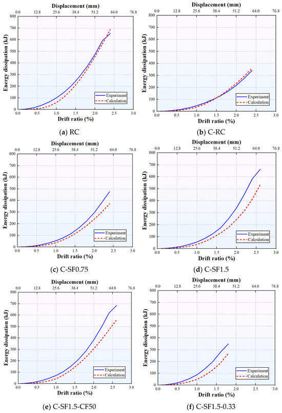
Figure 11.
Comparison of energy dissipation.
Table 5.
Comparison of energy dissipation values.
6. Conclusions
This study proposes a finite spring calculation method (FSCM) for predicting the cyclic response of FRP-reinforced SFRC composite walls under seismic loads, with special consideration of the bond-slip effect of CFRP bars. Six composite wall specimens with varying longitudinal bar types, VF, concrete strengths, and axial compression ratios were selected for numerical calculation, and the accuracy of the FSCM was verified by comparing with experimental results. The primary conclusions are summarized below:
- (1)
- The FSCM effectively captures the “pinching effect” of FRP-reinforced SFRC composite walls, which is attributed to its rational integration of two core mechanical behaviors: first, the linear-elastic property of CFRP bars that minimizes plastic deformation accumulation, and second, the bond-slip effect between CFRP bars and SFRC that induces stress redistribution at the interface. By discretizing the wall into elastic zones and plastic hinge zones and introducing bond-slip spring elements, the FSCM avoids the overestimation of interface collaborative work (a common defect of traditional models) and thus reproduces the typical seismic response of the composite walls. For all six specimens, the average error of peak load prediction ranges from −3.36% to 7.36%, confirming its reliability in bearing capacity evaluation.
- (2)
- The FSCM’s high accuracy in predicting residual displacement (consistent with experimental variation trends) stems from its ability to characterize the synergistic effect of CFRP bars and SFRC. CFRP bars provide excellent self-centering capacity due to their linear-elasticity, while SFRC restrains crack propagation and reduces irreversible deformation through fiber bridging. The model’s discrete spring framework effectively quantifies this synergy, which is why the predicted residual displacement of CFRP-reinforced specimens is significantly lower than that of traditional RC specimens (e.g., 63.44% reduction for C-RC vs. RC at 1.8% drift ratio) and correctly reflects the influences of VF, concrete strength, and axial compression ratio.
- (3)
- The FSCM successfully captures the reduced energy dissipation of CFRP-reinforced specimens (e.g., 47.51% lower CED for C-RC vs. RC), which is a direct reflection of CFRP bars’ lack of plastic hysteretic energy dissipation. However, the model slightly underestimates the CED of SFRC specimens (maximum error of −22.96%), primarily due to the neglect of concrete tensile strength in the current framework. This limitation indicates that the tensile contribution of SFRC (enhanced by steel fiber bridging) plays a non-negligible role in energy dissipation, which should be incorporated in future model optimization.
- (4)
- The FSCM’s core modeling philosophy lies in “simplification without loss of key mechanisms”, which addresses the trade-off between computational efficiency and prediction accuracy in composite structure numerical analysis. Unlike complex finite element models that require refined meshing and high computational costs, the FSCM achieves efficient and accurate prediction by focusing on core mechanical behaviors (bond-slip, material inherent properties) and simplifying non-critical details. This philosophy provides a new perspective for the development of numerical methods for high-performance composite structures: prioritizing the characterization of key interface and material synergistic effects over excessive model complexity.
Limitations and future research directions: The present work paves the way for numerical simulation investigations targeting FRP-reinforced SFRC composite structures, but there are still aspects that can be further improved: (1) A notable limitation of the proposed FSCM is the neglect of SFRC’s tensile behavior (e.g., fiber crack-bridging and tensile energy absorption), which leads to deviations in the energy dissipation calculation of SFRC specimens. Future research can introduce a reasonable SFRC tensile constitutive model to improve the accuracy of energy dissipation prediction. (2) The bond-slip model adopted in this study is modified based on monotonic loading tests, and the cyclic degradation mechanism of bond behavior under long-term or high-frequency cyclic loading needs to be further explored and incorporated into the model. (3) The proposed method is only validated against the present experimental program, which restricts its direct generality to other FRP-reinforced concrete structural systems with different parameters or configurations. Future research will conduct more diverse experimental tests and further validate and optimize the method to broaden its applicability. (4) This study focuses on proposing the FSCM calculation method and theoretical model; the current FSCM is still in preliminary design and improvement, thus only capable of outputting global mechanical responses and unable to simulate local deformation and damage morphology. Future research will further improve the FSCM and develop its damage morphology simulation function, while optimizing the calculation framework and expanding the model validation scope to enhance its universality; we also have a preliminary idea for integrating the element-level FSCM into full structural system analysis, which will be explored by standardizing its input/output interfaces, improving computational efficiency and verifying with typical cases on the basis of the optimized FSCM.
Author Contributions
Conceptualization, M.L. and J.T.; methodology, Y.S. and J.L.; software, Y.S.; validation, M.L. and Z.Q.; formal analysis, investigation, data curation, and writing—original draft, M.L.; writing—review and editing, M.L. and J.T.; supervision, J.L.; project administration and funding acquisition, J.T. All authors have read and agreed to the published version of the manuscript.
Funding
This research was funded by NSFC, grant number 52408321; Guangdong Provincial Fund, grant number 2024A1515140056; Higher Education Research Fund of DGUT, grant number GJ202402.
Data Availability Statement
The data presented in this study are available in the article.
Conflicts of Interest
The authors declare no conflicts of interest.
References
- Yu, J.; Wang, H.Y.; Chang, Y.F. Experimental and numerical study on seismic performance of a novel RC-UHPC composite shear wall. J. Build. Eng. 2025, 115, 114553. [Google Scholar] [CrossRef]
- Cai, Z.P.; Hao, J.P.; Sun, X.L.; Xue, Q.; Wang, J.H. Seismic performance of a novel prestressed high-performance exposed CFST column base. J. Constr. Steel Res. 2026, 240, 110265. [Google Scholar] [CrossRef]
- Zhou, X.Z.; Zhou, Y.; Zhang, X.T.; Liu, X.Y.; Lin, Y.H. Study on the seismic performance of fully wrapped CFRP-retrofitted RC frame structures considering the influence of infill walls. Structures 2025, 81, 110292. [Google Scholar] [CrossRef]
- Wang, H.Z.; Li, X.P.; Jiang, H.J.; Huang, W.Y. Development of replaceable self-centering energy-dissipation component for seismic resilient RC shear wall. Eng. Struct. 2025, 334, 120237. [Google Scholar] [CrossRef]
- Zhang, Y.Y.; Xie, R.J.; Zuo, X.B.; Fan, W. Experimental and numerical investigation of post-earthquake recoverability of a novel precast segmental double-column pier. Eng. Struct. 2025, 343, 121052. [Google Scholar] [CrossRef]
- Liu, X.; Xie, Q.; Liang, H.B.; Zhang, X.L. Post-earthquake recover strategy for substations based on seismic resilience evaluation. Eng. Struct. 2023, 279, 115583. [Google Scholar] [CrossRef]
- Li, S.R.; Jiang, H.J.; Liu, X.J. Seismic performance of earthquake resilient structure with replaceable components. J. Build. Eng. 2025, 99, 111597. [Google Scholar] [CrossRef]
- Zhu, F.R.; Zhang, M.J.; Zhang, D.W.; Wang, D.Y.; Wang, Z.Y.; Zhang, Y.D. Seismic behavior of FRP-retrofitted rectangular RC columns subjected to oblique horizontal earthquake actions. Constr. Build. Mater. 2025, 482, 141737. [Google Scholar] [CrossRef]
- Wang, D.; Gu, J.B.; Tao, Y.; Chen, G.M.; Shi, Q.X. Seismic behavior of FRP confined steel reinforced UHPC columns. Structures 2025, 72, 108263. [Google Scholar] [CrossRef]
- Fu, H.; Guo, K.; Wu, Z.; Mai, R.; Chin, C.-L.; Ma, C.-K. Experimental investigation of a novel CFRP-Steel composite tube-confined seawater-sea sand concrete intermediate long column. Int. J. Integr. Eng. 2024, 16, 466–475. [Google Scholar] [CrossRef]
- Zhou, H.; Lu, C.; Liu, J.; Han, S.; Li, T. Evaluation of three FRP connector systems on mechanical performance in FRP bars-reinforced concrete beams. Structures 2025, 82, 110817. [Google Scholar] [CrossRef]
- Lei, S.; Wu, F.W.; Liu, L.J.; Chen, X.Y.; Peng, B. Seismic repair of damaged columns with CFRP bars and sheets. Structures 2025, 81, 110357. [Google Scholar] [CrossRef]
- Li, X.P.; Yin, L.; Zhao, J.; Jiang, Y.B. Studies on seismic performance of CFRP and steel bars hybrid reinforced concrete frames. Structures 2024, 64, 106545. [Google Scholar] [CrossRef]
- Zhang, X.C.; Hu, Y.W.; Zhao, J.; Sun, P.X.; Li, G.H. Numerical analysis on seismic performance of CFRP bar reinforced concrete columns with magnetorheological damper. Compos. Part B Eng. 2026, 312, 113350. [Google Scholar] [CrossRef]
- Yuan, W.Y.; Jia, Z.L.; Hu, M.H.; Han, Q.; Liao, W.Z.; Bai, Y.L. Seismic behavior of bridge columns with FRP-reinforced ECC at plastic hinge zones. Eng. Struct. 2025, 338, 120573. [Google Scholar] [CrossRef]
- Liu, M.Y.; Zhao, J.; Sun, Y.P. Seismic behavior and skeleton curve model of SFRC shear walls reinforced by CFRP bars. Constr. Build. Mater. 2025, 492, 142975. [Google Scholar] [CrossRef]
- Zhao, J.; Zhao, Y.; Shen, F.; Li, X.; Yin, L. Experimental and numerical study on seismic behavior of high energy-consuming resilient concrete shear walls reinforced by CFRP bars and magnetorheological dampers. Structures 2024, 68, 107210. [Google Scholar] [CrossRef]
- Jayanth, K.; Suresh, G.S. Steel fibre reinforced concrete (SFRC) under repeated slow cyclic loading in compression—Experimental and theoretical studies. Structures 2025, 78, 109303. [Google Scholar] [CrossRef]
- Xiang, D.; Liu, S.Q.; Li, Y.J.; Liu, Y.Q. Improvement of flexural and cyclic performance of bridge deck slabs by utilizing steel fiber reinforced concrete (SFRC). Constr. Build. Mater. 2022, 329, 127184. [Google Scholar] [CrossRef]
- Hu, Z.M.; Wang, J.F.; Shen, Q.H.; Li, B.B.; Liu, Y. Mechanical analysis of eccentrically loaded SFRC columns reinforced by high-strength rebars: Testing and FE modelling. Eng. Struct. 2025, 343, 121042. [Google Scholar] [CrossRef]
- Carrillo, J.; Hube, M.; Blandon, C.; Mata, R.; Abellan-Garcia, J. Compression behavior of square and circular SFRC columns confined with external steel straps. J. Build. Eng. 2024, 98, 110993. [Google Scholar] [CrossRef]
- Secer, R.; Keskin, O.; Arslan, G.; Sengun, K. Influence of CFRP on the shear strength of RC and SFRC beams. Constr. Build. Mater. 2017, 153, 16–24. [Google Scholar] [CrossRef]
- Wan, C.; Li, C.C.; Zhu, H.T.; Zheng, Y.X.; Cheng, S.Z. Serviceability evaluation model of SFRC beams reinforced with FRP bars based on deformation control. Structures 2023, 56, 104807. [Google Scholar] [CrossRef]
- Li, X.P.; Gao, N.; Zhao, J.; Yin, L. Study on seismic performance of steel fiber reinforced concrete shear walls with hybrid steel strands and HRB400 bars in the boundary elements. Constr. Build. Mater. 2024, 430, 136447. [Google Scholar] [CrossRef]
- Smith, M. ABAQUS/Standard User’s Manual, Version 6.9; Dassault Systèmes Simulia Corp: Johnston, RI, USA, 2009. [Google Scholar]
- Mazzoni, S.; McKenna, F.; Scott, M.H.; Fenves, G.L. The Open System for Earthquake Engineering Simulation (OpenSEES) User Command-Language Manual; University of California: Berkeley, CA, USA, 2006. [Google Scholar]
- Zhang, Z.; Ashour, A.; Ge, W. Cyclic behavior of steel-FRP composite bars reinforced ultra-high performance concrete frames: Experimental, numerical, and restoring force model analysis. Constr. Build. Mater. 2025, 495, 143745. [Google Scholar] [CrossRef]
- Mansouri, S.; Rahai, A.; Hosseinnia, A.; Aslani, F. Performance evaluation of FRP-strengthened self-compacting concrete filled double-steel-plate composite shear walls: Experimental and numerical studies. Structures 2025, 81, 110174. [Google Scholar] [CrossRef]
- He, N.; Chen, Z.P.; Tang, J.Y.; Zhao, Y.J.; Liang, Y.; Zhou, J. Experimental study on bond behavior of CFRP bars in coral sea-sand seawater concrete. Structures 2025, 79, 109526. [Google Scholar] [CrossRef]
- Wang, Z.K.; Duan, J.X.; Pan, H.J.; Zhao, J.; Wang, P.; Wang, F.; Du, M.R. Accelerated testing and long-term prediction of tensile and bond properties of CFRP bars embedded in moist sulphoaluminate cement (SAC) concrete. Constr. Build. Mater. 2025, 494, 143202. [Google Scholar] [CrossRef]
- Zhou, Y.; Wu, Z.; Li, H. The effects of different FRP/concrete bond–slip laws on the 3D FE modeling of retrofitted RC beams—Sensitivity analysis. Comput. Concr. 2018, 22, 251–260. [Google Scholar] [CrossRef]
- Guo, K.; Guo, Q.; Wang, Y.F. Effect of Bond-Slip on Dynamic Response of FRP-Confined RC Columns with Non-Linear Damping. Appl. Sci. 2021, 11, 2124. [Google Scholar] [CrossRef]
- Zhao, J.; Liu, M.Y.; Quan, Z.R.; Gao, N.; Lei, B.B. Experimental and numerical investigation on seismic performance of SFRC shear walls with CFRP bars. Structures 2024, 67, 106958. [Google Scholar] [CrossRef]
- Zhao, J.; Li, X.P.; Zhang, X.C. Experimental and theoretical research on bond performance between CFRP bar and concrete under monotonic and reversed cyclic loading. Eng. Struct. 2021, 246, 112994. [Google Scholar] [CrossRef]
- Zhao, J.; Kou, Z.K.; Li, X.P.; Liu, X.F. Cyclic bond behavior and bond stress-slip model of steel strands in steel fiber reinforced concrete. Constr. Build. Mater. 2024, 449, 138405. [Google Scholar] [CrossRef]
- Sun, Y.P.; Fukuhara, T.; Kitajima, H. Analytical study of cyclic response of concrete members made of high-strength materials. In Proceedings of the 8th US National Conference on Earthquake Engineering; San Francisco, CA, USA, 18–22 April 2006, Curran Associates, Inc.: Red Hook, NY, USA, 2006; Volume No. 1581. [Google Scholar]
- Funato, Y.; Sun, Y.; Takeuchi, T.; Cai, G. Modeling and application of bond characteristic of high-strength reinforcing bar with spiral grooves. Proc. Jpn. Concr. Inst. 2012, 34, 157–162. [Google Scholar]
- Sun, Y.; Fukuhara, T.; Chen, J. Modeling of complete stress-strain relationship for high-strength steels. In Proceedings of the 1st European Conference on Earthquake and Seismology; Geneva, Switzerland, 3–8 September 2006, Swiss Society for Earthquake Engineering and Structural Dynamics (SGEB): Zurich, Switzerland, 2006. [Google Scholar]
- GB 50010-2010; Chinese Standard for Design of Concrete Structures. Architecture and Building Press: Beijing, China, 2010.
- Tian, F.; Sakino, K.; Sun, Y. Effect of strain gradient on the flexural behavior of confined R/C columns. J. Struct. Eng. 1997, 43B, 191–198. [Google Scholar]
- Menegotto, M.; Pinto, P.E. Method of analysis for cyclically loaded reinforced concrete plane frames including changes in geometry and non-elastic behavior of elements under combined normal force and bending. In Proceedings of the IABSE Symposium on the Resistance and Ultimate Deformation of Structures Acted by Well-Defined Repeated Loads, Lisbon, Portugal, 12–14 September 1973. [Google Scholar]
- Cai, G.C. Seismic Performance and Evaluation of Resilient Circular Concrete Columns. Ph.D. Dissertation, Kobe University, Kobe, Japan, 2014. [Google Scholar]
- Quayyum, S. Bond Behavior of Fibre Reinforced Polymer (FRP) Rebars in Concrete. Master’s Thesis, University of British Columbia, Okanagan, Kelowna, BC, Canada, 2010. [Google Scholar]


Disclaimer/Publisher’s Note: The statements, opinions and data contained in all publications are solely those of the individual author(s) and contributor(s) and not of MDPI and/or the editor(s). MDPI and/or the editor(s) disclaim responsibility for any injury to people or property resulting from any ideas, methods, instructions or products referred to in the content. |
© 2026 by the authors. Licensee MDPI, Basel, Switzerland. This article is an open access article distributed under the terms and conditions of the Creative Commons Attribution (CC BY) license.